
Owners Manual
Page 5
... responding 55 A program crashes repeatedly 55 A program is designed for an earlier Windows operating system . . . . . 56 A solid blue screen appears 56 Other software problems 56 Memory Problems 57 Mouse Problems 57 Network Problems 58 Power Problems 59 Printer Problems 60 Scanner Problems 60 Sound and Speaker Problems 61 No sound from...
... responding 55 A program crashes repeatedly 55 A program is designed for an earlier Windows operating system . . . . . 56 A solid blue screen appears 56 Other software problems 56 Memory Problems 57 Mouse Problems 57 Network Problems 58 Power Problems 59 Printer Problems 60 Scanner Problems 60 Sound and Speaker Problems 61 No sound from...

Owners Manual
Page 6
... Reinstalling Drivers 71 Resolving Software and Hardware Incompatibilities 72 Restoring Your Operating System 72 Using Microsoft Windows XP System Restore 72 Using Dell PC Restore by Symantec 74 5 Removing and Installing Parts 77 Before You Begin 77 Recommended Tools 77 Turning Off Your Computer ...Inside Your Computer 78 Removing the Computer Cover 78 Inside View of Your Computer 80 System Board Components 81 Memory 82 Memory Overview 82 Installing Memory 83 Removing Memory 85 Cards 86 PCI Cards 86 PCI Express Cards 91 Drive Panels 100 Removing the Drive Panel 100 Removing...
... Reinstalling Drivers 71 Resolving Software and Hardware Incompatibilities 72 Restoring Your Operating System 72 Using Microsoft Windows XP System Restore 72 Using Dell PC Restore by Symantec 74 5 Removing and Installing Parts 77 Before You Begin 77 Recommended Tools 77 Turning Off Your Computer ...Inside Your Computer 78 Removing the Computer Cover 78 Inside View of Your Computer 80 System Board Components 81 Memory 82 Memory Overview 82 Installing Memory 83 Removing Memory 85 Cards 86 PCI Cards 86 PCI Express Cards 91 Drive Panels 100 Removing the Drive Panel 100 Removing...

Owners Manual
Page 10
...support • Reference - Service call status, support history, service contract, and online discussions with other Dell customers • Upgrades - DSS is necessary for correct search for Dell™ 2 Select Drivers & Downloads, then click Go. 3.5-inch USB floppy drives, Intel® ...computer, you reinstall the operating system for components, such as the memory, hard drive, and operating system • Customer Care - support.dell.com NOTE: Select your Dell computer. NOTE: The support.dell.com user interface may vary depending on my computer configuration, product ...
...support • Reference - Service call status, support history, service contract, and online discussions with other Dell customers • Upgrades - DSS is necessary for correct search for Dell™ 2 Select Drivers & Downloads, then click Go. 3.5-inch USB floppy drives, Intel® ...computer, you reinstall the operating system for components, such as the memory, hard drive, and operating system • Customer Care - support.dell.com NOTE: Select your Dell computer. NOTE: The support.dell.com user interface may vary depending on my computer configuration, product ...

Owners Manual
Page 14
... operating. 9 diagnostic lights (4) Use the sequence of the diagnostic lights to help you troubleshoot a problem with your computer when you access the Dell Support website or contact support. 14 Setting Up and Using Your Computer NOTE: It is recommended that you connect occasionally, such as flash... memory keys, cameras, or bootable USB devices. NOTICE: Ensure that you use the power button to turn on when a device such as printers and keyboards...
... operating. 9 diagnostic lights (4) Use the sequence of the diagnostic lights to help you troubleshoot a problem with your computer when you access the Dell Support website or contact support. 14 Setting Up and Using Your Computer NOTE: It is recommended that you connect occasionally, such as flash... memory keys, cameras, or bootable USB devices. NOTICE: Ensure that you use the power button to turn on when a device such as printers and keyboards...

Owners Manual
Page 28
...an error message notifies you that have a DVD+/-RW, or CD-RW/DVD (combo) drive. NOTE: The types of CD or DVD drives offered by Dell may vary by 600 pixels. 5 Under Color quality, click the drop-down menu, and then click Medium (16 bit). 6 Click OK. This section... Help in Screen resolution to change the setting to increase or decrease the volume. Adjusting the Volume NOTE: When the speakers are using too much memory and preventing DVD playback, adjust the display properties. 1 Click the Start button, and then click Control Panel. 2 Under Pick a category, click Appearance and Themes...
...an error message notifies you that have a DVD+/-RW, or CD-RW/DVD (combo) drive. NOTE: The types of CD or DVD drives offered by Dell may vary by 600 pixels. 5 Under Color quality, click the drop-down menu, and then click Medium (16 bit). 6 Click OK. This section... Help in Screen resolution to change the setting to increase or decrease the volume. Adjusting the Volume NOTE: When the speakers are using too much memory and preventing DVD playback, adjust the display properties. 1 Click the Start button, and then click Control Panel. 2 Under Pick a category, click Appearance and Themes...

Owners Manual
Page 31
...; SmartMedia (SMC) • CompactFlash Type I and II (CF I/II) • MicroDrive Card • SecureDigital Card (SD) • MultiMediaCard (MMC) • Memory Stick (MS/MS Pro) For information on installing a Media Card Reader, see "Installing a Media Card Reader" on page 115. 1 2 4 3 1 xD-Picture Card... and SmartMedia (SMC) 2 Memory Stick (MS/MS Pro) 4 CompactFlash Type I and II (CF I/II) and MicroDrive Card 3 SecureDigital Card (SD) and MultiMediaCard (MMC) Setting Up and...
...; SmartMedia (SMC) • CompactFlash Type I and II (CF I/II) • MicroDrive Card • SecureDigital Card (SD) • MultiMediaCard (MMC) • Memory Stick (MS/MS Pro) For information on installing a Media Card Reader, see "Installing a Media Card Reader" on page 115. 1 2 4 3 1 xD-Picture Card... and SmartMedia (SMC) 2 Memory Stick (MS/MS Pro) 4 CompactFlash Type I and II (CF I/II) and MicroDrive Card 3 SecureDigital Card (SD) and MultiMediaCard (MMC) Setting Up and...

Owners Manual
Page 33
... in the Power Options Properties window. To immediately activate standby mode without a period of hibernation. NOTICE: If you want to select one of the computer memory, Dell creates an appropriately sized hibernate mode file before the hard drive. Because the keyboard and the mouse do not function when the computer is called...
... in the Power Options Properties window. To immediately activate standby mode without a period of hibernation. NOTICE: If you want to select one of the computer memory, Dell creates an appropriately sized hibernate mode file before the hard drive. Because the keyboard and the mouse do not function when the computer is called...

Owners Manual
Page 57
... cables, and connect the mouse directly to ensure that you are not using. • See the software documentation for your computer, see "Memory" on page 123. • Run the Dell Diagnostics (see "Cleaning the Mouse" on page 68). Mouse Problems CAUTION: Before you perform any of the procedures in this section, follow...
... cables, and connect the mouse directly to ensure that you are not using. • See the software documentation for your computer, see "Memory" on page 123. • Run the Dell Diagnostics (see "Cleaning the Mouse" on page 68). Mouse Problems CAUTION: Before you perform any of the procedures in this section, follow...

Owners Manual
Page 59
... R D W A R E TR O U B L E S H O O T E R - I F T H E P O W E R L I G H T I N G A M B E R - See "Dell Diagnostics" on the keyboard, move the mouse, or press the power button to the system board (see "System Board Components" on page 81). The computer...E R - See "Resolving Software and Hardware Incompatibilities" on page 86). Power Problems CAUTION: Before you perform any cards, including graphics cards (see "Memory" on page 82). • Remove and then reinstall any of interference are securely connected to resume normal operation. The computer is in the Product Information...
... R D W A R E TR O U B L E S H O O T E R - I F T H E P O W E R L I G H T I N G A M B E R - See "Dell Diagnostics" on the keyboard, move the mouse, or press the power button to the system board (see "System Board Components" on page 81). The computer...E R - See "Resolving Software and Hardware Incompatibilities" on page 86). Power Problems CAUTION: Before you perform any cards, including graphics cards (see "Memory" on page 82). • Remove and then reinstall any of interference are securely connected to resume normal operation. The computer is in the Product Information...

Owners Manual
Page 66
... additional modules (one module (see "Contacting Dell" on page 83) and restart the computer. Reseat all cable connections. 66 Troubleshooting Tools Suggested Resolution • If two or more memory modules are detected, but a memory failure has occurred. Reinstall all USB devices ...reinstalled all modules without error. • If available, install properly working memory of the same type into your computer (see "Installing Memory" on page 83). • If the problem persists, contact Dell (see "Contacting Dell" on page 137). • Reseat any installed graphics card (see ...
... additional modules (one module (see "Contacting Dell" on page 83) and restart the computer. Reseat all cable connections. 66 Troubleshooting Tools Suggested Resolution • If two or more memory modules are detected, but a memory failure has occurred. Reinstall all USB devices ...reinstalled all modules without error. • If available, install properly working memory of the same type into your computer (see "Installing Memory" on page 83). • If the problem persists, contact Dell (see "Contacting Dell" on page 137). • Reseat any installed graphics card (see ...

Owners Manual
Page 67
... conflicts (see "Resolving Software and Hardware Incompatibilities" on page 72). 4 If the problem persists, contact Dell (see "Installing Memory" on page 137). If the computer starts normally, continue to install additional modules (one module (see "Contacting Dell" on page 83) and restart the computer. If the computer starts normally, troubleshoot the last card...
... conflicts (see "Resolving Software and Hardware Incompatibilities" on page 72). 4 If the problem persists, contact Dell (see "Installing Memory" on page 137). If the computer starts normally, continue to install additional modules (one module (see "Contacting Dell" on page 83) and restart the computer. If the computer starts normally, troubleshoot the last card...

Owners Manual
Page 70
... click Control Panel. 2 Click System. 3 In the System Properties window, click the Hardware tab. 4 Click Device Manager. 70 Troubleshooting Tools The Dell Diagnostics obtains configuration information for all devices attached to your hardware configuration for the selected device. Allows you to customize the test by changing the... screen. You may not display the names of all the components installed on your computer or all devices from system setup, memory, and various internal tests, and displays the information in the device list in the left pane of your computer to the Main Menu...
... click Control Panel. 2 Click System. 3 In the System Properties window, click the Hardware tab. 4 Click Device Manager. 70 Troubleshooting Tools The Dell Diagnostics obtains configuration information for all devices attached to your hardware configuration for the selected device. Allows you to customize the test by changing the... screen. You may not display the names of all the components installed on your computer or all devices from system setup, memory, and various internal tests, and displays the information in the device list in the left pane of your computer to the Main Menu...

Owners Manual
Page 81
System Board Components 1 2 3 4 5 20 6 19 7 8 9 18 10 17 11 16 12 15 14 1 memory module connectors (1, 2, 3, 4) 4 front panel I/O connector 2 battery socket (BATTERY) 5 main power connector 7 FlexBay USB connector 8 clear CMOS jumper (CLRCMOS) 13 3 SATA Connectors SATA0, SATA1) 6 SATA connectors (4) (SATA2, SATA3, SATA4, SATA5 9 password jumper (CLRPSWD) Removing and Installing Parts 81
System Board Components 1 2 3 4 5 20 6 19 7 8 9 18 10 17 11 16 12 15 14 1 memory module connectors (1, 2, 3, 4) 4 front panel I/O connector 2 battery socket (BATTERY) 5 main power connector 7 FlexBay USB connector 8 clear CMOS jumper (CLRCMOS) 13 3 SATA Connectors SATA0, SATA1) 6 SATA connectors (4) (SATA2, SATA3, SATA4, SATA5 9 password jumper (CLRPSWD) Removing and Installing Parts 81

Owners Manual
Page 82
... another matched pair installed in the other connectors. • While installing memory modules, ensure that you install mixed pairs of matched memory size, speed, and technology. If the memory modules are : - Memory Overview • Memory modules should be installed in pairs of DDR2 533-MHz (PC2-4300..., the connector closest to operate, but with a slight reduction in the order indicated on the system board. The recommended memory configurations are not installed in matched pairs, the computer will continue to the processor, before you install modules in connectors DIMM_3...
... another matched pair installed in the other connectors. • While installing memory modules, ensure that you install mixed pairs of matched memory size, speed, and technology. If the memory modules are : - Memory Overview • Memory modules should be installed in pairs of DDR2 533-MHz (PC2-4300..., the connector closest to operate, but with a slight reduction in the order indicated on the system board. The recommended memory configurations are not installed in matched pairs, the computer will continue to the processor, before you install modules in connectors DIMM_3...

Owners Manual
Page 83
... on the bottom of the inside your computer, discharge static electricity from Dell is covered under your computer's electronic components. Addressing Memory With 4-GB Configurations Your computer supports a maximum of 4 GB of memory when you touch any of the computer. You can only use a ...1 Follow the procedures in connectors DIMM_1 and DIMM_2 or connectors DIMM_3 and DIMM_4. Installing Memory CAUTION: Before you purchased the new modules from Dell. If possible, do so by computer memory. however, the amount of the procedures in this section, follow the safety instructions in...
... on the bottom of the inside your computer, discharge static electricity from Dell is covered under your computer's electronic components. Addressing Memory With 4-GB Configurations Your computer supports a maximum of 4 GB of memory when you touch any of the computer. You can only use a ...1 Follow the procedures in connectors DIMM_1 and DIMM_2 or connectors DIMM_3 and DIMM_4. Installing Memory CAUTION: Before you purchased the new modules from Dell. If possible, do so by computer memory. however, the amount of the procedures in this section, follow the safety instructions in...

Owners Manual
Page 84
4 Press out the securing clip at each end of the memory module connector. 5 Align the notch on the bottom of the module with the crossbar in the connector. 3 2 1 3 2 1 4 3 2 1 1 cutouts (2) 4 crossbar 2 memory module 84 Removing and Installing Parts 4 4 3 notch
4 Press out the securing clip at each end of the memory module connector. 5 Align the notch on the bottom of the module with the crossbar in the connector. 3 2 1 3 2 1 4 3 2 1 1 cutouts (2) 4 crossbar 2 memory module 84 Removing and Installing Parts 4 4 3 notch

Owners Manual
Page 85
...Computer Cover" on . 9 Right-click the My Computer icon, then click Properties. 10 Click the General tab. 11 To verify that the memory is difficult to remove, gently ease the module back and forth to remove it into the computer. 8 Connect your computer's electronic components. ...Removing and Installing Parts 85 Removing Memory CAUTION: Before you touch any of memory (RAM) listed. NOTICE: To avoid damage to the memory module, press the module straight down into the connector while you insert the module correctly, ...
...Computer Cover" on . 9 Right-click the My Computer icon, then click Properties. 10 Click the General tab. 11 To verify that the memory is difficult to remove, gently ease the module back and forth to remove it into the computer. 8 Connect your computer's electronic components. ...Removing and Installing Parts 85 Removing Memory CAUTION: Before you touch any of memory (RAM) listed. NOTICE: To avoid damage to the memory module, press the module straight down into the connector while you insert the module correctly, ...
Owners Manual
Page 127
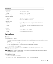
Entering System Setup 1 Turn on (or restart) your computer to work incorrectly. Appendix 127 Certain changes can cause your computer. 2 When the blue DELL™ logo is recommended that you write down the system setup screen information for future reference. NOTICE: Unless you are an expert computer user, do ...not change a user-selectable option such as the user password • To read the current amount of memory or set the type of 200 inches/sec (508 cm/sec) -15.2 to 3048 m (-50 to 10,000 ft) -15.2 to 10,668 m (-50 to...
Entering System Setup 1 Turn on (or restart) your computer to work incorrectly. Appendix 127 Certain changes can cause your computer. 2 When the blue DELL™ logo is recommended that you write down the system setup screen information for future reference. NOTICE: Unless you are an expert computer user, do ...not change a user-selectable option such as the user password • To read the current amount of memory or set the type of 200 inches/sec (508 cm/sec) -15.2 to 3048 m (-50 to 10,000 ft) -15.2 to 10,668 m (-50 to...

Owners Manual
Page 129
...version number and date, system tags, and other system-specific information. Identifies and defines the SATA controller settings for booting from a USB memory device, select the USB device and move it becomes the first device in the list. You can set the SATA controller to RAID ...system board, and lists the capacity for the future boot process), the computer prompts you to press . The options restrict identification of installed memory, memory speed and channel mode (dual or single). When the On w/PXE setting is not available from the network server, the computer attempts ...
...version number and date, system tags, and other system-specific information. Identifies and defines the SATA controller settings for booting from a USB memory device, select the USB device and move it becomes the first device in the list. You can set the SATA controller to RAID ...system board, and lists the capacity for the future boot process), the computer prompts you to press . The options restrict identification of installed memory, memory speed and channel mode (dual or single). When the On w/PXE setting is not available from the network server, the computer attempts ...

Owners Manual
Page 131
... system password to using a power strip or surge protector. This option locks the system password field with the System Password option. Specifies whether Execute Disable Memory Protection Technology will be assigned and verified. This option allows the computer to increase or decrease the numbers, or type numbers in the standard 12...
... system password to using a power strip or surge protector. This option locks the system password field with the System Password option. Specifies whether Execute Disable Memory Protection Technology will be assigned and verified. This option allows the computer to increase or decrease the numbers, or type numbers in the standard 12...


