Owner's Manual
Page 23
...the display settings for your TV. 4 Connect the VGA or DVI monitor. For information on page 55. 2 Connect one screen to the S-video input connector on your graphics card, see the user's guide in the display settings. • In clone mode, both monitors display the same image. • In extended ...desktop mode, you can drag objects from one end of the S-video cable to the TV-OUT connector on the back of the computer. 3...
...the display settings for your TV. 4 Connect the VGA or DVI monitor. For information on page 55. 2 Connect one screen to the S-video input connector on your graphics card, see the user's guide in the display settings. • In clone mode, both monitors display the same image. • In extended ...desktop mode, you can drag objects from one end of the S-video cable to the TV-OUT connector on the back of the computer. 3...
Owner's Manual
Page 27
Advanced Tab The Advanced tab allows you to: • Place the power options icon in card that can accept 4-pin IEEE 1394 devices with multimedia devices because it speeds the transfer of an ... of data between computers and peripheral devices. IEEE 1394 IEEE 1394 is only available if you to devices such as digital video cameras. This connector is a digital interface that uses IEEE 1394. Hibernate Tab The Hibernate tab allows you purchased an add... on the Power Schemes tab, click the Enable hibernate support check box on page 57). To purchase a card, contact Dell.
Advanced Tab The Advanced tab allows you to: • Place the power options icon in card that can accept 4-pin IEEE 1394 devices with multimedia devices because it speeds the transfer of an ... of data between computers and peripheral devices. IEEE 1394 IEEE 1394 is only available if you to devices such as digital video cameras. This connector is a digital interface that uses IEEE 1394. Hibernate Tab The Hibernate tab allows you purchased an add... on the Power Schemes tab, click the Enable hibernate support check box on page 57). To purchase a card, contact Dell.
Owner's Manual
Page 103
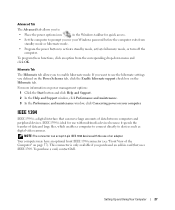
... Memory Type Memory connectors Memory capacities Minimum memory Maximum memory BIOS address Computer Information Chipset DMA channels Interrupt levels BIOS chip (NVRAM) NIC System clock Video Type Audio Type Intel® Pentium® 4 Socket-T with Hyper-Threading technology 1 MB or 2 MB dual-channel 400-, 533-, and 667-MHz DDR2 four 256... Integrated network interface capable of 10/100 communication 800- or 1066-MHz data rate (depending on your processor) PCI Express Internal 7.1 channel or PCI option cards Appendix 103
... Memory Type Memory connectors Memory capacities Minimum memory Maximum memory BIOS address Computer Information Chipset DMA channels Interrupt levels BIOS chip (NVRAM) NIC System clock Video Type Audio Type Intel® Pentium® 4 Socket-T with Hyper-Threading technology 1 MB or 2 MB dual-channel 400-, 533-, and 667-MHz DDR2 four 256... Integrated network interface capable of 10/100 communication 800- or 1066-MHz data rate (depending on your processor) PCI Express Internal 7.1 channel or PCI option cards Appendix 103

Owner's Manual
Page 105
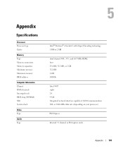
...microphone, surround, and center/Low Frequency Effects (LFE) channel; Drives Externally accessible: Available devices Internally accessible: Connectors External connectors: IEEE 1394 Video Network adapter USB Audio System board connectors: Primary IDE drive Serial ATA FlexBay Drive Fan PCI PCI Express x1 PCI Express x4 PCI Express... and five back-panel USB 2.0-compliant connectors five back-panel connectors for optional floppy drive or optional Media Card Reader (3.5-inch bay devices) 5-pin connector three 120-pin connectors 36-pin connector 98-pin connector 164-pin connector Appendix 105
...microphone, surround, and center/Low Frequency Effects (LFE) channel; Drives Externally accessible: Available devices Internally accessible: Connectors External connectors: IEEE 1394 Video Network adapter USB Audio System board connectors: Primary IDE drive Serial ATA FlexBay Drive Fan PCI PCI Express x1 PCI Express x4 PCI Express... and five back-panel USB 2.0-compliant connectors five back-panel connectors for optional floppy drive or optional Media Card Reader (3.5-inch bay devices) 5-pin connector three 120-pin connectors 36-pin connector 98-pin connector 164-pin connector Appendix 105
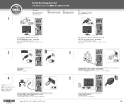
Setup Diagram
Page 1
... of the modem connectors. DVI→ DVI: If your Product Information Guide. If you set up and operate your Dell™ computer, read and follow the safety instructions in your computer has a DVI video card, use that connector. 2 Connect a keyboard and a mouse. 4 NOTE: Not all modems have two connectors. Set Up Your Computer...
... of the modem connectors. DVI→ DVI: If your Product Information Guide. If you set up and operate your Dell™ computer, read and follow the safety instructions in your computer has a DVI video card, use that connector. 2 Connect a keyboard and a mouse. 4 NOTE: Not all modems have two connectors. Set Up Your Computer...


