Reference Guide
Page 7
...systems or who want to upgrade their computers. The chapter includes a basic orientation to use before calling Dell for system components such as expansion cards, memory, and drives. • Chapter 6, "Getting Help," provides information on reinstalling software. • Chapter 5, "...mation on preventive maintenance to new in this guide can be used for anyone who uses a Dell Dimension 900 system. Warranty and Return Policy Information Dell Computer Corporation ("Dell") manufactures its hardware products from parts and components that are new or equivalent to protect the computer...
...systems or who want to upgrade their computers. The chapter includes a basic orientation to use before calling Dell for system components such as expansion cards, memory, and drives. • Chapter 6, "Getting Help," provides information on reinstalling software. • Chapter 5, "...mation on preventive maintenance to new in this guide can be used for anyone who uses a Dell Dimension 900 system. Warranty and Return Policy Information Dell Computer Corporation ("Dell") manufactures its hardware products from parts and components that are new or equivalent to protect the computer...

Reference Guide
Page 8
...answers to Programs-> Dell Documents, and then click Dell Dimension Help. To access this guide, blocks of your computer. CAUTION: A CAUTION indicates a potentially hazardous situation which, if not avoided, may also double-click the Dell Documents icon on your hard-disk drive to provide last-... by -step instructions for setting up your computer system. • The Dell Dimension Systems Setup Guide describes how to properly set up your operating system and connect a printer. • The Dell Dimension 900 System Help describes the features and operation of text may be installed on the...
...answers to Programs-> Dell Documents, and then click Dell Dimension Help. To access this guide, blocks of your computer. CAUTION: A CAUTION indicates a potentially hazardous situation which, if not avoided, may also double-click the Dell Documents icon on your hard-disk drive to provide last-... by -step instructions for setting up your computer system. • The Dell Dimension Systems Setup Guide describes how to properly set up your operating system and connect a printer. • The Dell Dimension 900 System Help describes the features and operation of text may be installed on the...
Reference Guide
Page 9
... appears on the monitor screen or display. They are enclosed in the Courier New font. Example: "Use the format command to format the diskette in drive A." • Filenames and directory names are part of keys to be typed. Example: "Type format a: to . . . ." Screen text is a message or text that you substitute...
... appears on the monitor screen or display. They are enclosed in the Courier New font. Example: "Use the format command to format the diskette in drive A." • Filenames and directory names are part of keys to be typed. Example: "Type format a: to . . . ." Screen text is a message or text that you substitute...

Reference Guide
Page 12
... Drives 3-8 Optical Drives 3-8 Hard-Disk Drives 3-9 Running the Dell Diagnostics 3-9 Starting the Dell Diagnostics 3-10 Dell Diagnostics Main Screen 3-12 Using the Dell ...Diagnostics 3-13 Menu 3-13 Keys 3-14 Device Group 3-14 Device 3-14 Test 3-14 Versions 3-14 Software Solutions 4-1 Using the Power Management Features in Windows 98, Windows Me, and Windows 2000 4-1 Reinstalling Drivers 4-2 Your System's Drivers 4-3 Using the Dell Dimension...
... Drives 3-8 Optical Drives 3-8 Hard-Disk Drives 3-9 Running the Dell Diagnostics 3-9 Starting the Dell Diagnostics 3-10 Dell Diagnostics Main Screen 3-12 Using the Dell ...Diagnostics 3-13 Menu 3-13 Keys 3-14 Device Group 3-14 Device 3-14 Test 3-14 Versions 3-14 Software Solutions 4-1 Using the Power Management Features in Windows 98, Windows Me, and Windows 2000 4-1 Reinstalling Drivers 4-2 Your System's Drivers 4-3 Using the Dell Dimension...

Reference Guide
Page 13
...Support Service 6-3 Problems With Your Order 6-3 Product Information 6-3 Returning Items for Warranty Repair or Credit 6-4 Before You Call 6-4 Dell Contact Numbers 6-6 System Specifications A-1 System Setup Program B-1 Entering the System Setup Program B-1 Using the System Setup Program B-1 System... Setup Screens and Options B-3 Main Screen B-4 System Information Screen B-5 Product Information Screen B-6 Disk Drives Screen B-7 IDE Primary Channel Master Submenu B-8 Onboard Peripherals Screen B-9 Boot Options Screen B-11 Date and Time Screen B-13...
...Support Service 6-3 Problems With Your Order 6-3 Product Information 6-3 Returning Items for Warranty Repair or Credit 6-4 Before You Call 6-4 Dell Contact Numbers 6-6 System Specifications A-1 System Setup Program B-1 Entering the System Setup Program B-1 Using the System Setup Program B-1 System... Setup Screens and Options B-3 Main Screen B-4 System Information Screen B-5 Product Information Screen B-6 Disk Drives Screen B-7 IDE Primary Channel Master Submenu B-8 Onboard Peripherals Screen B-9 Boot Options Screen B-11 Date and Time Screen B-13...

Reference Guide
Page 14
... Diagnostics Checklist 6-5 Figure B-1. IDE Primary Channel Master Submenu B-8 Figure B-6. Diagnostics Menu 3-12 Figure 3-2. Dell Diagnostics Main Screen 3-13 Figure 5-1. Disk Drives Screen Menu B-7 Figure B-5. Padlock Ring 1-4 Figure 2-1. System Board Features 2-6 Figure 2-5. Removing the Riser-Board Bracket 2-...11 Figure 2-6. Drive Shelf 2-20 Figure 2-14. Main Screen Menu B-4 Figure B-2. Onboard Peripherals Screen Menu B-9 Figure B-7. Date and ...
... Diagnostics Checklist 6-5 Figure B-1. IDE Primary Channel Master Submenu B-8 Figure B-6. Diagnostics Menu 3-12 Figure 3-2. Dell Diagnostics Main Screen 3-13 Figure 5-1. Disk Drives Screen Menu B-7 Figure B-5. Padlock Ring 1-4 Figure 2-1. System Board Features 2-6 Figure 2-5. Removing the Riser-Board Bracket 2-...11 Figure 2-6. Drive Shelf 2-20 Figure 2-14. Main Screen Menu B-4 Figure B-2. Onboard Peripherals Screen Menu B-9 Figure B-7. Date and ...

Reference Guide
Page 15
... 2-8 Processor Mode Jumper Settings 2-9 NVRAM Jumper Settings 2-9 Boot-Block Jumper Settings 2-10 Start-Up Routine Indications 3-3 Dell Contact Numbers 6-6 Technical Specifications A-1 System Setup Navigation Keys B-2 Main Screen Menu Options B-4 System Information Screen Menu Options B-5 Product Information ...Screen Menu Options B-6 Disk Drives Screen Menu Options B-7 IDE Primary Channel Master Submenu Options B-8 Onboard Peripherals Screen Menu Options B-9 Boot Options Screen ...
... 2-8 Processor Mode Jumper Settings 2-9 NVRAM Jumper Settings 2-9 Boot-Block Jumper Settings 2-10 Start-Up Routine Indications 3-3 Dell Contact Numbers 6-6 Technical Specifications A-1 System Setup Navigation Keys B-2 Main Screen Menu Options B-4 System Information Screen Menu Options B-5 Product Information ...Screen Menu Options B-6 Disk Drives Screen Menu Options B-7 IDE Primary Channel Master Submenu Options B-8 Onboard Peripherals Screen Menu Options B-9 Boot Options Screen ...

Reference Guide
Page 18
...compliant devices. NOTE: Inconsistencies in the drive or the CD. • Full compliance with PCI specification 2.2. • Full compliance with these devices while the system is located on your operating system documentation. 1-2 Dell Dimension 900 System Reference and Troubleshooting Guide For your... Figure 2-7) is available for use with Dimension 900 system-specific expansion cards available only from Dell (see "Available Upgrades," found later in your original system configuration, you at system start-up if your hard-disk drive has become unreliable. cation 1.0A. &#...
...compliant devices. NOTE: Inconsistencies in the drive or the CD. • Full compliance with PCI specification 2.2. • Full compliance with these devices while the system is located on your operating system documentation. 1-2 Dell Dimension 900 System Reference and Troubleshooting Guide For your... Figure 2-7) is available for use with Dimension 900 system-specific expansion cards available only from Dell (see "Available Upgrades," found later in your original system configuration, you at system start-up if your hard-disk drive has become unreliable. cation 1.0A. &#...

Reference Guide
Page 24
... directly onto the system board. 2-4 Dell Dimension 900 System Reference and Troubleshooting Guide These cables supply power to the system board and to an interface connector on the system board. Some hardware options are the interface cables for internal drives. Removing the Bezel 4. An interface cable connects a drive to internal drives. bezel front panel tabs (3) Figure...
... directly onto the system board. 2-4 Dell Dimension 900 System Reference and Troubleshooting Guide These cables supply power to the system board and to an interface connector on the system board. Some hardware options are the interface cables for internal drives. Removing the Bezel 4. An interface cable connects a drive to internal drives. bezel front panel tabs (3) Figure...

Reference Guide
Page 25
Inside the Computer expansion-card slots line-out connector USB connector video connector parallel port connector serial port connector keyboard connector support.dell.com Installing Upgrades on the System Board 2-5 diskette drive optical drive system board riser-board bracket power supply voltage-select switch AC power receptacle mouse connector Figure 2-3.
Inside the Computer expansion-card slots line-out connector USB connector video connector parallel port connector serial port connector keyboard connector support.dell.com Installing Upgrades on the System Board 2-5 diskette drive optical drive system board riser-board bracket power supply voltage-select switch AC power receptacle mouse connector Figure 2-3.

Reference Guide
Page 26
... (LED1) DC main power input connector (CN2) power button connector (JP1) power-button indicator connector (JP2) hard-disk drive activity indicator connector (JP3) USB port connector (CN6) line-out connector (PH1) audio signal cable connector (CN13) processor mode...connector (CN5) USB port connector (CN5) front audio/USB board interface connector (CN12) diskette-drive interface connector (CN16) battery socket (BT1) Figure 2-4. System Board Features 2-6 Dell Dimension 900 System Reference and Troubleshooting Guide System Board Figure 2-4 shows the system board connectors and sockets, ...
... (LED1) DC main power input connector (CN2) power button connector (JP1) power-button indicator connector (JP2) hard-disk drive activity indicator connector (JP3) USB port connector (CN6) line-out connector (PH1) audio signal cable connector (CN13) processor mode...connector (CN5) USB port connector (CN5) front audio/USB board interface connector (CN12) diskette-drive interface connector (CN16) battery socket (BT1) Figure 2-4. System Board Features 2-6 Dell Dimension 900 System Reference and Troubleshooting Guide System Board Figure 2-4 shows the system board connectors and sockets, ...

Reference Guide
Page 27
... connector DIMMn DIMM socket FN1 Processor fan connector JP1 Power button connector JP2 Power-button indicator connector JP3 Hard-disk drive activity indicator connector JP6 Password jumper JP7 Boot-block select jumper JPX1 Processor mode jumper JPX2 NVRAM jumper LED1 System board power indicator PH1 Line-...out connector SL1 Riser-board connector U9 Microprocessor socket NOTE: The Glossary in the system Help defines abbreviations and acronyms. support.dell.com Installing Upgrades on the System Board 2-7 u Table 2-1.
... connector DIMMn DIMM socket FN1 Processor fan connector JP1 Power button connector JP2 Power-button indicator connector JP3 Hard-disk drive activity indicator connector JP6 Password jumper JP7 Boot-block select jumper JPX1 Processor mode jumper JPX2 NVRAM jumper LED1 System board power indicator PH1 Line-...out connector SL1 Riser-board connector U9 Microprocessor socket NOTE: The Glossary in the system Help defines abbreviations and acronyms. support.dell.com Installing Upgrades on the System Board 2-7 u Table 2-1.

Reference Guide
Page 30
...of the diskette drive with one finger into the oval opening in your computer. Then slightly lift the back end of the riser-board bracket and gently pull the riser-board bracket toward the back of the computer until its edges, which may be sharp. 2-10 Dell Dimension 900 System Reference and... chapter. 2. Table 2-5. CAUTION: When handling the riser board bracket, always hold it from the front chassis slot and its two side diskette-drive slots are clear of the boot-block select jumper. Boot from top block setting NOTE: The Glossary in the system Help defines abbreviations and acronyms...
...of the diskette drive with one finger into the oval opening in your computer. Then slightly lift the back end of the riser-board bracket and gently pull the riser-board bracket toward the back of the computer until its edges, which may be sharp. 2-10 Dell Dimension 900 System Reference and... chapter. 2. Table 2-5. CAUTION: When handling the riser board bracket, always hold it from the front chassis slot and its two side diskette-drive slots are clear of the boot-block select jumper. Boot from top block setting NOTE: The Glossary in the system Help defines abbreviations and acronyms...

Reference Guide
Page 31
...in this process. 2. Replace the riser-board screw (see Figure 2-5). Replace the computer cover according to prevent it by its diskette-drive slots align with one finger into the oval opening Figure 2-5. Gently push the riser-board bracket toward the front of the computer ... the diskette-drive tabs (see Figure 2-5). diskette-drive slots and tabs (2) diskette drive front tab riser-board bracket riser-board securing tabs (5) screw back tabs (3) oval opening on top of the riser board and its edges, which may be sharp. 3. support.dell.com Installing Upgrades on the System...
...in this process. 2. Replace the riser-board screw (see Figure 2-5). Replace the computer cover according to prevent it by its diskette-drive slots align with one finger into the oval opening Figure 2-5. Gently push the riser-board bracket toward the front of the computer ... the diskette-drive tabs (see Figure 2-5). diskette-drive slots and tabs (2) diskette drive front tab riser-board bracket riser-board securing tabs (5) screw back tabs (3) oval opening on top of the riser board and its edges, which may be sharp. 3. support.dell.com Installing Upgrades on the System...
Reference Guide
Page 39
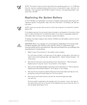
...face the front of system memory, the operating system may report 62 or 63 MB. Remove the drive shelf screws, and lift the drive shelf approximately one to the left of the diskette drive as you have to repeatedly reset this information after turning on when the computer is a danger ...bezel by the operating system is 1 or 2 MB less than the memory installed because that memory is disconnected from the front panel. 5. support.dell.com Installing Upgrades on the System Board 2-19 The battery can last several years. CAUTION: There is turned off to the instructions in "Removing ...
...face the front of system memory, the operating system may report 62 or 63 MB. Remove the drive shelf screws, and lift the drive shelf approximately one to the left of the diskette drive as you have to repeatedly reset this information after turning on when the computer is a danger ...bezel by the operating system is 1 or 2 MB less than the memory installed because that memory is disconnected from the front panel. 5. support.dell.com Installing Upgrades on the System Board 2-19 The battery can last several years. CAUTION: There is turned off to the instructions in "Removing ...

Reference Guide
Page 40
... damage the system board by prying off the socket or by breaking circuit traces on the system board (see Figure 2-14). 2-20 Dell Dimension 900 System Reference and Troubleshooting Guide screws (2) bezel drive shelf Figure 2-13. Otherwise, you pry out the battery with a blunt, nonconductive object, such as a plastic screwdriver. Insert the battery into...
... damage the system board by prying off the socket or by breaking circuit traces on the system board (see Figure 2-14). 2-20 Dell Dimension 900 System Reference and Troubleshooting Guide screws (2) bezel drive shelf Figure 2-13. Otherwise, you pry out the battery with a blunt, nonconductive object, such as a plastic screwdriver. Insert the battery into...

Reference Guide
Page 41
System Battery and Battery Socket 8. Restart the system, press when the blue Dell logo screen appears to their electrical outlets. 10. support.dell.com Installing Upgrades on the System Board 2-21 Lower the drive shelf and replace the two screws that you removed in step 5. 9. For instructions, see Appendix B, "System Setup Program." Replace the bezel, riser-board bracket, and computer cover, and reconnect your computer and devices to enter the system setup program, and restore the correct settings. battery socket (BT1) battery Figure 2-14.
System Battery and Battery Socket 8. Restart the system, press when the blue Dell logo screen appears to their electrical outlets. 10. support.dell.com Installing Upgrades on the System Board 2-21 Lower the drive shelf and replace the two screws that you removed in step 5. 9. For instructions, see Appendix B, "System Setup Program." Replace the bezel, riser-board bracket, and computer cover, and reconnect your computer and devices to enter the system setup program, and restore the correct settings. battery socket (BT1) battery Figure 2-14.

Reference Guide
Page 43
... is behaving erratically, back up Dell-installed driver files for Dell-installed devices. NOTE: In case of warranty replacement of your hard-disk drive, you made . Installing Additional Hardware and Software If the problem you are preserved on the Dell Dimension ResourceCD. Backing Up Data Files ...You can help support technicians diagnose and fix the problem. The driver files are experiencing began after you will receive a blank formatted drive from Dell. If the problem is resolved, check any...
... is behaving erratically, back up Dell-installed driver files for Dell-installed devices. NOTE: In case of warranty replacement of your hard-disk drive, you made . Installing Additional Hardware and Software If the problem you are preserved on the Dell Dimension ResourceCD. Backing Up Data Files ...You can help support technicians diagnose and fix the problem. The driver files are experiencing began after you will receive a blank formatted drive from Dell. If the problem is resolved, check any...

Reference Guide
Page 48
..., your modem is functioning properly. message, and then select Safe Mode from those devices. • Plug the speakers into the headphone jack of the optical drive, make sure the headphone volume control is not turned to an analog line only. NOTE: If your modem can dial and connect to one Internet... damage the modem. Modem NOTICE: Connect the modem to its maximum setting. For Windows 98, Windows Me, and Windows 2000, press when you cannot connect. 3-6 Dell Dimension 900 System Reference and Troubleshooting Guide Restart the system. 2.
..., your modem is functioning properly. message, and then select Safe Mode from those devices. • Plug the speakers into the headphone jack of the optical drive, make sure the headphone volume control is not turned to an analog line only. NOTE: If your modem can dial and connect to one Internet... damage the modem. Modem NOTICE: Connect the modem to its maximum setting. For Windows 98, Windows Me, and Windows 2000, press when you cannot connect. 3-6 Dell Dimension 900 System Reference and Troubleshooting Guide Restart the system. 2.
Reference Guide
Page 50
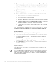
... the new diskette works, the original one may cause some higherspeed CD-ROM drives to known good location on the system. 6. Replace the riser-board bracket and computer cover, connect all drives. 3-8 Dell Dimension 900 System Reference and Troubleshooting Guide If you are being used. Replace the patch cable or network cable from causing an...
... the new diskette works, the original one may cause some higherspeed CD-ROM drives to known good location on the system. 6. Replace the riser-board bracket and computer cover, connect all drives. 3-8 Dell Dimension 900 System Reference and Troubleshooting Guide If you are being used. Replace the patch cable or network cable from causing an...


