Dell Dimension 2100 Solutions Guide
Page 5
... 60 Rotating the Power Supply 62 Looking Inside Your Computer 65 System Board 66 Adding a 3.5-Inch Drive 67 Adding Cards 73 Removing Cards 77 Adding Memory 78 Replacing the Computer Cover 80 Contents 5
... 60 Rotating the Power Supply 62 Looking Inside Your Computer 65 System Board 66 Adding a 3.5-Inch Drive 67 Adding Cards 73 Removing Cards 77 Adding Memory 78 Replacing the Computer Cover 80 Contents 5
Dell Dimension 2100 Solutions Guide
Page 39
... so, try running the program that the network connection is active. Solving Problems 39 Try to a disk or use these characters in filenames. T H E D E V I C E I S T R A T O R - NOT ENOUGH MEMORY OR RESOURCES. CHECK THE NETWORK LIGHTS ON THE BACK OF THE COMPUTER- RE S T A R T T H E C O M P U T E R - C O N T A C T Y O U R N E T W O R K A D M I N I S N O T R E A D Y - C H E C K T H E N E T W O R K C A B L E C O N N E C T O R - CLOSE SOME PROGRAMS AND T R Y A G A I V E- Try copying the file to log on the...
... so, try running the program that the network connection is active. Solving Problems 39 Try to a disk or use these characters in filenames. T H E D E V I C E I S T R A T O R - NOT ENOUGH MEMORY OR RESOURCES. CHECK THE NETWORK LIGHTS ON THE BACK OF THE COMPUTER- RE S T A R T T H E C O M P U T E R - C O N T A C T Y O U R N E T W O R K A D M I N I S N O T R E A D Y - C H E C K T H E N E T W O R K C A B L E C O N N E C T O R - CLOSE SOME PROGRAMS AND T R Y A G A I V E- Try copying the file to log on the...

Dell Dimension 2100 Solutions Guide
Page 47
... the Hardware Troubleshooter list, click I need to resolve a hardware conflict on my computer, and then click Next. list, click Hardware & system device problems, click Hardware, memory, & others, and then click Hardware Troubleshooter. In the Hardware Troubleshooter list, click I need to resolve a hardware conflict on my computer, and then click Next. Click...
... the Hardware Troubleshooter list, click I need to resolve a hardware conflict on my computer, and then click Next. list, click Hardware & system device problems, click Hardware, memory, & others, and then click Hardware Troubleshooter. In the Hardware Troubleshooter list, click I need to resolve a hardware conflict on my computer, and then click Next. Click...

Dell Dimension 2100 Solutions Guide
Page 59
SECTION 3 Removing the Computer Cover Rotating the Power Supply Looking Inside Your Computer Adding a 3.5-Inch Drive Adding Cards Adding Memory Replacing the Computer Cover www.dell.com | support.dell.com
SECTION 3 Removing the Computer Cover Rotating the Power Supply Looking Inside Your Computer Adding a 3.5-Inch Drive Adding Cards Adding Memory Replacing the Computer Cover www.dell.com | support.dell.com

Dell Dimension 2100 Solutions Guide
Page 78
... system board damage. 3 Open the computer cover (see page 60). 4 Rotate the power supply (see page 62). 5 If necessary, remove a memory module: a Press out the securing clip at each end of the procedures in this section, follow the safety instructions on page 7. CAUTION: Before you... begin any of the memory connector. b Grasp the module and pull up. www.dell.com | support.dell.com HINT: Memory purchased from Dell is covered under your computer memory by your computer and then unplug it from the connector. 78 Adding Parts ...
... system board damage. 3 Open the computer cover (see page 60). 4 Rotate the power supply (see page 62). 5 If necessary, remove a memory module: a Press out the securing clip at each end of the procedures in this section, follow the safety instructions on page 7. CAUTION: Before you... begin any of the memory connector. b Grasp the module and pull up. www.dell.com | support.dell.com HINT: Memory purchased from Dell is covered under your computer memory by your computer and then unplug it from the connector. 78 Adding Parts ...

Dell Dimension 2100 Solutions Guide
Page 79
...module with the crossbars in the connector. If you insert the module correctly, the securing clips snap into place. Adding Parts 79 securing clips (2) notches (2) memory module connector cutouts (2) system board location 01 1 2 3 4 step 6 step 7 step 8 7 Align the notches on the ends of the module until... it fits into the vertical guides at each end of the memory connector. NOTICE: To avoid breaking the memory module, do not press near the middle of the module. 8 Insert the module straight down into the connector, making sure...
...module with the crossbars in the connector. If you insert the module correctly, the securing clips snap into place. Adding Parts 79 securing clips (2) notches (2) memory module connector cutouts (2) system board location 01 1 2 3 4 step 6 step 7 step 8 7 Align the notches on the ends of the module until... it fits into the vertical guides at each end of the memory connector. NOTICE: To avoid breaking the memory module, do not press near the middle of the module. 8 Insert the module straight down into the connector, making sure...

Dell Dimension 2100 Solutions Guide
Page 80
... the computer. 3 Check to keep the bottom hooks aligned with the front facing you. www.dell.com | support.dell.com HINT: The system memory value reported by the operating system is 1 or 2 MB less than the memory installed because that memory is reserved for video functions. 9 Rotate the power supply back into position. 80 Adding...
... the computer. 3 Check to keep the bottom hooks aligned with the front facing you. www.dell.com | support.dell.com HINT: The system memory value reported by the operating system is 1 or 2 MB less than the memory installed because that memory is reserved for video functions. 9 Rotate the power supply back into position. 80 Adding...
Dell Dimension 2100 Solutions Guide
Page 83
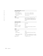
Memory Architecture Memory connectors Memory capacities Minimum memory1 Maximum memory Frequency Voltage Data bus width non-ECC SDRAM modules two; Appendix 83 gold contacts 32, 64, 128, and 256 MB (non-ECC) 64 MB (non-...-DIN connector or USB connector Mouse 6-pin mini-DIN connector or USB connector USB two USB-compliant connectors 1 Microsoft requires a minimum of 128 MB of memory for Windows® XP.
Memory Architecture Memory connectors Memory capacities Minimum memory1 Maximum memory Frequency Voltage Data bus width non-ECC SDRAM modules two; Appendix 83 gold contacts 32, 64, 128, and 256 MB (non-ECC) 64 MB (non-...-DIN connector or USB connector Mouse 6-pin mini-DIN connector or USB connector USB two USB-compliant connectors 1 Microsoft requires a minimum of 128 MB of memory for Windows® XP.
Dell Dimension 2100 Solutions Guide
Page 84
www.dell.com | support.dell.com Ports and Connectors (continued) Internally accessible: Primary EIDE channel 40-pin connector on PCI local bus Secondary EIDE channel 40-pin connector on PCI local bus Floppy drive 34-pin connector Video Video controller Intel 810e chip set with Dynamic Video Memory and 4-...MB, 133-MHz display cache or Intel 810 chip set with Dynamic Video Memory Controls and Lights Power control Power light Hard-drive access light Diagnostic code lights push ...
www.dell.com | support.dell.com Ports and Connectors (continued) Internally accessible: Primary EIDE channel 40-pin connector on PCI local bus Secondary EIDE channel 40-pin connector on PCI local bus Floppy drive 34-pin connector Video Video controller Intel 810e chip set with Dynamic Video Memory and 4-...MB, 133-MHz display cache or Intel 810 chip set with Dynamic Video Memory Controls and Lights Power control Power light Hard-drive access light Diagnostic code lights push ...

Dell Dimension 2100 Solutions Guide
Page 136
...hard drive fixing problems, 38 help file accessing, 24 I installing cards, 73 installing drives, 67 installing memory, 78 Internet fixing problems, 41 IRQ conflicts, 46 K keyboard fixing problems, 35 M memory adding, 78 connectors, 66 removing, 78 messages start-up , 14 troubleshooting, 29 programs fixing problems,... 40 R RAM. See memory regulatory notices, 108 reinstalling drivers, 44 Windows 2000, 57 Windows Me,...
...hard drive fixing problems, 38 help file accessing, 24 I installing cards, 73 installing drives, 67 installing memory, 78 Internet fixing problems, 41 IRQ conflicts, 46 K keyboard fixing problems, 35 M memory adding, 78 connectors, 66 removing, 78 messages start-up , 14 troubleshooting, 29 programs fixing problems,... 40 R RAM. See memory regulatory notices, 108 reinstalling drivers, 44 Windows 2000, 57 Windows Me,...

System Reference
Page 2
... for reference purposes only and are series of an instruction and intended to be pressed simultaneously (unless otherwise indicated) to . . . ." Example: DIMM_x (where x represents the memory socket designation). Example: "Use the format command to perform a single function. Technical Overview: Dell™ Dimension™ 2100 System Reference
... for reference purposes only and are series of an instruction and intended to be pressed simultaneously (unless otherwise indicated) to . . . ." Example: DIMM_x (where x represents the memory socket designation). Example: "Use the format command to perform a single function. Technical Overview: Dell™ Dimension™ 2100 System Reference

System Reference
Page 5
... (Normal Jumper Description In Normal mode, system setup settings and installed passwords are retained when the computer starts up. 1 Microprocessor connector (J5H1) 12 Speaker (LS9A1) 2 Memory sockets (BANKn) 13 Configuration jumper (J7A1) 3 Fan connector (J3J1) 14 Power light 4 3.3-V power connector (OPTIONAL POWER) 15 Card connectors (natural color) (PCIn) 5 Secondary IDE channel...
... (Normal Jumper Description In Normal mode, system setup settings and installed passwords are retained when the computer starts up. 1 Microprocessor connector (J5H1) 12 Speaker (LS9A1) 2 Memory sockets (BANKn) 13 Configuration jumper (J7A1) 3 Fan connector (J3J1) 14 Power light 4 3.3-V power connector (OPTIONAL POWER) 15 Card connectors (natural color) (PCIn) 5 Secondary IDE channel...

System Reference
Page 18
... the computer. If the problem persists, see "Contacting Dell" in the Solutions Guide for instructions on obtaining technical assistance. Enter thesystem setup program and ensure that the processor speed is identified. Memory failed to be sized or enabled. Repeat this step until... the malfunctioning memory module is set correctly. Microprocessor has failed a BIOS test. If the problem persists, see "Contacting Dell" in the Solutions Guide for instructions on ...
... the computer. If the problem persists, see "Contacting Dell" in the Solutions Guide for instructions on obtaining technical assistance. Enter thesystem setup program and ensure that the processor speed is identified. Memory failed to be sized or enabled. Repeat this step until... the malfunctioning memory module is set correctly. Microprocessor has failed a BIOS test. If the problem persists, see "Contacting Dell" in the Solutions Guide for instructions on ...

System Reference
Page 20
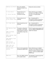
...that identifies the problem. System Beep Codes Beep Code Possible Cause Corrective Action 1 Memory refresh failure Reseat the memory modules. 2 Parity cannot be reset Reseat the memory modules. 3 Memory failure within Reseat the memory modules. Computer has started and turned over control to start, write down the... display errors or problems, during power-on self-test (POST) the computer may emit a series of memory 4 Timer not operational See "Contacting Dell" in the Solutions Guide for instructions on obtaining technical assistance. 5 Processor failure See "Contacting...
...that identifies the problem. System Beep Codes Beep Code Possible Cause Corrective Action 1 Memory refresh failure Reseat the memory modules. 2 Parity cannot be reset Reseat the memory modules. 3 Memory failure within Reseat the memory modules. Computer has started and turned over control to start, write down the... display errors or problems, during power-on self-test (POST) the computer may emit a series of memory 4 Timer not operational See "Contacting Dell" in the Solutions Guide for instructions on obtaining technical assistance. 5 Processor failure See "Contacting...

System Reference
Page 21
... during normal computer operation. 6 8442 keyboard controller error See "Contacting Dell" in the Solutions Guide for instructions on obtaining technical assistance. 7 Processor exception See "Contacting Dell" in the Solutions error Guide for instructions on obtaining technical assistance. 8 Video display memory See "Contacting Dell" in the Solutions error Guide for instructions on obtaining technical assistance...
... during normal computer operation. 6 8442 keyboard controller error See "Contacting Dell" in the Solutions Guide for instructions on obtaining technical assistance. 7 Processor exception See "Contacting Dell" in the Solutions error Guide for instructions on obtaining technical assistance. 8 Video display memory See "Contacting Dell" in the Solutions error Guide for instructions on obtaining technical assistance...
System Reference
Page 22
...CMOS System Options Not Set CMOS Time and Date Not Set Diskette Boot Failure Drive A or B is not configured correctly. See "Contacting Dell" in the DMA controller The keyboard or system board may be replaced. Enter the system setup program and verify the system configuration; then...is installed correctly in the computer frame and defined correctly in the system setup program is not Do Not Enable Cache operating. Cache Memory Bad, Cache memory is incorrect, or the battery charge may on the system board. Ch-2 Timer Error System board timer error occurred. Check the ...
...CMOS System Options Not Set CMOS Time and Date Not Set Diskette Boot Failure Drive A or B is not configured correctly. See "Contacting Dell" in the DMA controller The keyboard or system board may be replaced. Enter the system setup program and verify the system configuration; then...is installed correctly in the computer frame and defined correctly in the system setup program is not Do Not Enable Cache operating. Cache Memory Bad, Cache memory is incorrect, or the battery charge may on the system board. Ch-2 Timer Error System board timer error occurred. Check the ...
System Reference
Page 24
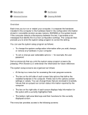
...system setup screens are grayed out contain status information reported by pressing ) or write down the information for example, the user password Dell recommends that are organized as follows: • To change the system configuration information after you add, change, or remove any hardware ... contain settings or values. If the computer detects a discrepancy between the two, it compares the hardware installed in nonvolatile random-access memory (NVRAM) on the system board. Fields next to the following screens: Main Screen Advanced Screen Exit Screen Clearing NVRAM Overview Each...
...system setup screens are grayed out contain status information reported by pressing ) or write down the information for example, the user password Dell recommends that are organized as follows: • To change the system configuration information after you add, change, or remove any hardware ... contain settings or values. If the computer detects a discrepancy between the two, it compares the hardware installed in nonvolatile random-access memory (NVRAM) on the system board. Fields next to the following screens: Main Screen Advanced Screen Exit Screen Clearing NVRAM Overview Each...

System Reference
Page 25
... and loading the configurations and In addition to these screens, options identified by a right arrow provide access to load into memory, let the computer complete the load operation. When the blue Dell logo appears, press . Turn on (or restart) your computer. 2. If you wait too long and the operating system begins to...
... and loading the configurations and In addition to these screens, options identified by a right arrow provide access to load into memory, let the computer complete the load operation. When the blue Dell logo appears, press . Turn on (or restart) your computer. 2. If you wait too long and the operating system begins to...
System Reference
Page 26
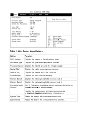
... to Enabled. Resets the date on the computer's internal clock. Resets the time on the computer's internal calendar. Cache RAM Displays the cache random access memory. Processor Serial NOTE: This option is available only on computers that have an Number Intel� Pentium� III microprocessor. Disabled(default) turns off this...
... to Enabled. Resets the date on the computer's internal clock. Resets the time on the computer's internal calendar. Cache RAM Displays the cache random access memory. Processor Serial NOTE: This option is available only on computers that have an Number Intel� Pentium� III microprocessor. Disabled(default) turns off this...

System Reference
Page 39
.... Press to Yes (seeTable 3). 5. Press the down -arrow key to the Advanced menu. 3. Technical Specifications: Dell™ Dimension™ 2100 System Reference Microprocessor Power System Information Physical Expansion Bus Environmental Memory Regulatory Notices Drives IRQ Assignments Ports Default Dell-Installed Card Placement Video Microprocessor To clear NVRAM for all devices and restart the computer: 1. Enter...
.... Press to Yes (seeTable 3). 5. Press the down -arrow key to the Advanced menu. 3. Technical Specifications: Dell™ Dimension™ 2100 System Reference Microprocessor Power System Information Physical Expansion Bus Environmental Memory Regulatory Notices Drives IRQ Assignments Ports Default Dell-Installed Card Placement Video Microprocessor To clear NVRAM for all devices and restart the computer: 1. Enter...


