Dell Dimension 2100 Solutions Guide
Page 5
... 60 Rotating the Power Supply 62 Looking Inside Your Computer 65 System Board 66 Adding a 3.5-Inch Drive 67 Adding Cards 73 Removing Cards 77 Adding Memory 78 Replacing the Computer Cover 80 Contents 5
... 60 Rotating the Power Supply 62 Looking Inside Your Computer 65 System Board 66 Adding a 3.5-Inch Drive 67 Adding Cards 73 Removing Cards 77 Adding Memory 78 Replacing the Computer Cover 80 Contents 5
Dell Dimension 2100 Solutions Guide
Page 39
... is too large to restore computer resources. Try to log on the START HERE sheet for your computer to fit on the disk. NOT ENOUGH MEMORY OR RESOURCES. Close all windows and open . C H E C K T H E N E T W O R K C A B L E C O N N E C T O R - THE FILE BEING COPIED IS TOO LARGE FOR THE DESTINATION...
... is too large to restore computer resources. Try to log on the START HERE sheet for your computer to fit on the disk. NOT ENOUGH MEMORY OR RESOURCES. Close all windows and open . C H E C K T H E N E T W O R K C A B L E C O N N E C T O R - THE FILE BEING COPIED IS TOO LARGE FOR THE DESTINATION...

Dell Dimension 2100 Solutions Guide
Page 47
... the Device Manager list. 7 Double-click the icon for the specific device in the Search Results list. list, click Hardware & system device problems, click Hardware, memory, & others, and then click Hardware Troubleshooter. Click Hardware Troubleshooter in the expanded list. The Properties window appears. 8 Resolve any conflicting device listed to bring up...
... the Device Manager list. 7 Double-click the icon for the specific device in the Search Results list. list, click Hardware & system device problems, click Hardware, memory, & others, and then click Hardware Troubleshooter. Click Hardware Troubleshooter in the expanded list. The Properties window appears. 8 Resolve any conflicting device listed to bring up...

Dell Dimension 2100 Solutions Guide
Page 59
SECTION 3 Removing the Computer Cover Rotating the Power Supply Looking Inside Your Computer Adding a 3.5-Inch Drive Adding Cards Adding Memory Replacing the Computer Cover www.dell.com | support.dell.com
SECTION 3 Removing the Computer Cover Rotating the Power Supply Looking Inside Your Computer Adding a 3.5-Inch Drive Adding Cards Adding Memory Replacing the Computer Cover www.dell.com | support.dell.com

Dell Dimension 2100 Solutions Guide
Page 78
...dell.com | support.dell.com HINT: Memory purchased from Dell is difficult to remove, gently ease the module back and forth to an electrical outlet discharges residual electricity and can increase your computer and then unplug it from the connector. 78 Adding Parts CAUTION: Before you begin any of memory supported by installing memory... modules on the system board. NOTICE: To disconnect a network cable, first unplug the cable from your computer memory by your computer warranty. See page 83 for...
...dell.com | support.dell.com HINT: Memory purchased from Dell is difficult to remove, gently ease the module back and forth to an electrical outlet discharges residual electricity and can increase your computer and then unplug it from the connector. 78 Adding Parts CAUTION: Before you begin any of memory supported by installing memory... modules on the system board. NOTICE: To disconnect a network cable, first unplug the cable from your computer memory by your computer warranty. See page 83 for...

Dell Dimension 2100 Solutions Guide
Page 79
securing clips (2) notches (2) memory module connector cutouts (2) system board location 01 1 2 3 4 step 6 step 7 step 8 7 Align the notches on the ends of the module with the crossbars in the connector. 6 ... connector. Press firmly on the bottom of the module until it fits into the vertical guides at each end of the memory connector. Adding Parts 79 NOTICE: To avoid breaking the memory module, do not press near the middle of the module. 8 Insert the module straight down into the connector, making sure...
securing clips (2) notches (2) memory module connector cutouts (2) system board location 01 1 2 3 4 step 6 step 7 step 8 7 Align the notches on the ends of the module with the crossbars in the connector. 6 ... connector. Press firmly on the bottom of the module until it fits into the vertical guides at each end of the memory connector. Adding Parts 79 NOTICE: To avoid breaking the memory module, do not press near the middle of the module. 8 Insert the module straight down into the connector, making sure...

Dell Dimension 2100 Solutions Guide
Page 80
...cover: 1 Rotate the power supply back into place (see page 64). 2 Check all cable connections, especially those that memory is 1 or 2 MB less than the memory installed because that might have come loose during your work. Fold cables and unused connectors out of the computer together until the... cover clicks into position. 80 Adding Parts www.dell.com | support.dell.com HINT: The system memory value reported by the operating system is reserved for video functions. 9 Rotate the power supply back into place (see ...
...cover: 1 Rotate the power supply back into place (see page 64). 2 Check all cable connections, especially those that memory is 1 or 2 MB less than the memory installed because that might have come loose during your work. Fold cables and unused connectors out of the computer together until the... cover clicks into position. 80 Adding Parts www.dell.com | support.dell.com HINT: The system memory value reported by the operating system is reserved for video functions. 9 Rotate the power supply back into place (see ...
Dell Dimension 2100 Solutions Guide
Page 83
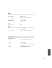
...-DIN connector or USB connector Mouse 6-pin mini-DIN connector or USB connector USB two USB-compliant connectors 1 Microsoft requires a minimum of 128 MB of memory for Windows® XP. Appendix 83 Memory Architecture Memory connectors Memory capacities Minimum memory1 Maximum memory Frequency Voltage Data bus width non-ECC SDRAM modules two;
...-DIN connector or USB connector Mouse 6-pin mini-DIN connector or USB connector USB two USB-compliant connectors 1 Microsoft requires a minimum of 128 MB of memory for Windows® XP. Appendix 83 Memory Architecture Memory connectors Memory capacities Minimum memory1 Maximum memory Frequency Voltage Data bus width non-ECC SDRAM modules two;
Dell Dimension 2100 Solutions Guide
Page 84
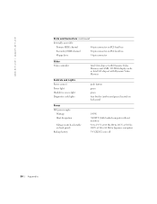
www.dell.com | support.dell.com Ports and Connectors (continued) Internally accessible: Primary EIDE channel 40-pin connector on PCI local bus Secondary EIDE channel 40-pin connector on PCI local bus Floppy drive 34-pin connector Video Video controller Intel 810e chip set with Dynamic Video Memory and 4-...MB, 133-MHz display cache or Intel 810 chip set with Dynamic Video Memory Controls and Lights Power control Power light Hard-drive access light Diagnostic code lights push ...
www.dell.com | support.dell.com Ports and Connectors (continued) Internally accessible: Primary EIDE channel 40-pin connector on PCI local bus Secondary EIDE channel 40-pin connector on PCI local bus Floppy drive 34-pin connector Video Video controller Intel 810e chip set with Dynamic Video Memory and 4-...MB, 133-MHz display cache or Intel 810 chip set with Dynamic Video Memory Controls and Lights Power control Power light Hard-drive access light Diagnostic code lights push ...

Dell Dimension 2100 Solutions Guide
Page 136
...x H hard drive fixing problems, 38 help file accessing, 24 I installing cards, 73 installing drives, 67 installing memory, 78 Internet fixing problems, 41 IRQ conflicts, 46 K keyboard fixing problems, 35 M memory adding, 78 connectors, 66 removing, 78 messages start-up , 14 troubleshooting, 29 programs fixing problems, 40 R ...driver, 16 setting up , 25 Windows, 39 modem fixing problems, 32 monitor fixing problems, 26 136 Index motherboard. See memory regulatory notices, 108 reinstalling drivers, 44 Windows 2000, 57 Windows Me, 55 ResourceCD, 44 return policy, 131 S safety instructions, 7 ScanDisk,...
...x H hard drive fixing problems, 38 help file accessing, 24 I installing cards, 73 installing drives, 67 installing memory, 78 Internet fixing problems, 41 IRQ conflicts, 46 K keyboard fixing problems, 35 M memory adding, 78 connectors, 66 removing, 78 messages start-up , 14 troubleshooting, 29 programs fixing problems, 40 R ...driver, 16 setting up , 25 Windows, 39 modem fixing problems, 32 monitor fixing problems, 26 136 Index motherboard. See memory regulatory notices, 108 reinstalling drivers, 44 Windows 2000, 57 Windows Me, 55 ResourceCD, 44 return policy, 131 S safety instructions, 7 ScanDisk,...

System Reference
Page 2
... and intended to as a command line). In contrast, commands presented in angle brackets. Technical Overview: Dell™ Dimension™ 2100 System Reference Example: • Commands presented in italics. They are presented in lowercase bold are for ...which you are instructed to type as part of a command (referred to be typed. • Keycaps are labels that you substitute a value. Example: DIMM_x (where x represents the memory...
... and intended to as a command line). In contrast, commands presented in angle brackets. Technical Overview: Dell™ Dimension™ 2100 System Reference Example: • Commands presented in italics. They are presented in lowercase bold are for ...which you are instructed to type as part of a command (referred to be typed. • Keycaps are labels that you substitute a value. Example: DIMM_x (where x represents the memory...

System Reference
Page 5
1 Microprocessor connector (J5H1) 12 Speaker (LS9A1) 2 Memory sockets (BANKn) 13 Configuration jumper (J7A1) 3 Fan connector (J3J1) 14 Power light 4 3.3-V power connector (OPTIONAL POWER) 15 Card connectors (natural color) (PCIn) 5 Secondary IDE channel ...
1 Microprocessor connector (J5H1) 12 Speaker (LS9A1) 2 Memory sockets (BANKn) 13 Configuration jumper (J7A1) 3 Fan connector (J3J1) 14 Power light 4 3.3-V power connector (OPTIONAL POWER) 15 Card connectors (natural color) (PCIn) 5 Secondary IDE channel ...

System Reference
Page 18
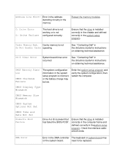
... has failed a BIOS test. If the problem persists, see "Contacting Dell" in theSolutions Guide for instructions on obtaining technical assistance. If the problem persists, remove all but one memory module, and then restart the computer. Enter thesystem setup program and ensure...and restart the computer. If the problem persists, see "Contacting Dell" in the Solutions Guide for instructions on obtaining technical assistance. Reseat the memory modules. If the problem persists, see "Contacting Dell" in the Solutions Guide for instructions on obtaining technical assistance....
... has failed a BIOS test. If the problem persists, see "Contacting Dell" in theSolutions Guide for instructions on obtaining technical assistance. If the problem persists, remove all but one memory module, and then restart the computer. Enter thesystem setup program and ensure...and restart the computer. If the problem persists, see "Contacting Dell" in the Solutions Guide for instructions on obtaining technical assistance. Reseat the memory modules. If the problem persists, see "Contacting Dell" in the Solutions Guide for instructions on obtaining technical assistance....

System Reference
Page 20
... cannot display errors or problems, during power-on obtaining technical assistance. the first 64 KB of memory 4 Timer not operational See "Contacting Dell" in the Solutions Guide for instructions on obtaining technical assistance. 5 Processor failure See "Contacting Dell" in Table 2. Table 2. If the computer emits a beep code and then fails to the operating...
... cannot display errors or problems, during power-on obtaining technical assistance. the first 64 KB of memory 4 Timer not operational See "Contacting Dell" in the Solutions Guide for instructions on obtaining technical assistance. 5 Processor failure See "Contacting Dell" in Table 2. Table 2. If the computer emits a beep code and then fails to the operating...

System Reference
Page 21
... during normal computer operation. 6 8442 keyboard controller error See "Contacting Dell" in the Solutions Guide for instructions on obtaining technical assistance. 7 Processor exception See "Contacting Dell" in the Solutions error Guide for instructions on obtaining technical assistance. 8 Video display memory See "Contacting Dell" in the Solutions error Guide for instructions on obtaining technical assistance...
... during normal computer operation. 6 8442 keyboard controller error See "Contacting Dell" in the Solutions Guide for instructions on obtaining technical assistance. 7 Processor exception See "Contacting Dell" in the Solutions error Guide for instructions on obtaining technical assistance. 8 Video display memory See "Contacting Dell" in the Solutions error Guide for instructions on obtaining technical assistance...
System Reference
Page 22
... incorrect, or the battery charge may on the system board. See "Contacting Dell" in the memory. Enter the system setup program and verify the system configuration; Check the interface cable at both ends. CMOS Battery State Low CMOS Checksum Failure ... the system setup program. Ch-2 Timer Error System board timer error occurred. DMA Error Error in thesystem setup program. Reseat the memory modules. CMOS Display Type Mismatch CMOS Memory Size Mismatch CMOS System Options Not Set CMOS Time and Date Not Set Diskette Boot Failure Drive A or B is installed correctly ...
... incorrect, or the battery charge may on the system board. See "Contacting Dell" in the memory. Enter the system setup program and verify the system configuration; Check the interface cable at both ends. CMOS Battery State Low CMOS Checksum Failure ... the system setup program. Ch-2 Timer Error System board timer error occurred. DMA Error Error in thesystem setup program. Reseat the memory modules. CMOS Display Type Mismatch CMOS Memory Size Mismatch CMOS System Options Not Set CMOS Time and Date Not Set Diskette Boot Failure Drive A or B is installed correctly ...
System Reference
Page 24
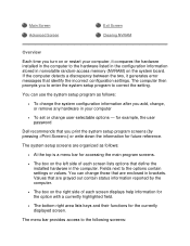
... reported by pressing ) or write down the information for the currently displayed screen. The system setup screens are enclosed in nonvolatile random-access memory (NVRAM) on the right side of each screen displays help information for the option with a currently highlighted field. • The bottom ...You can use the system setup program as follows: • At the top is a menu bar for example, the user password Dell recommends that define the installed hardware in the computer. Main Screen Advanced Screen Exit Screen Clearing NVRAM Overview Each time you print the system...
... reported by pressing ) or write down the information for the currently displayed screen. The system setup screens are enclosed in nonvolatile random-access memory (NVRAM) on the right side of each screen displays help information for the option with a currently highlighted field. • The bottom ...You can use the system setup program as follows: • At the top is a menu bar for example, the user password Dell recommends that define the installed hardware in the computer. Main Screen Advanced Screen Exit Screen Clearing NVRAM Overview Each time you print the system...

System Reference
Page 25
...for saving and loading the configurations and In addition to these screens, options identified by a right arrow provide access to load into memory, let the computer complete the load operation. Provides selections for the system password and setup password • Boot screen - Provides information... - Turn on (or restart) your computer. 2. Then shut down the computer and try again. • Main screen - When the blue Dell logo appears, press . Main Screen Provides settings for some computer features • Security screen - If you wait too long and the operating system...
...for saving and loading the configurations and In addition to these screens, options identified by a right arrow provide access to load into memory, let the computer complete the load operation. Provides selections for the system password and setup password • Boot screen - Provides information... - Turn on (or restart) your computer. 2. Then shut down the computer and try again. • Main screen - When the blue Dell logo appears, press . Main Screen Provides settings for some computer features • Security screen - If you wait too long and the operating system...
System Reference
Page 26
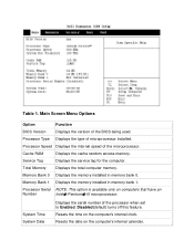
...; Pentium� III microprocessor. Processor Speed Displays the internal speed of microprocessor installed. Cache RAM Displays the cache random access memory. System Time System Date Displays the serial number of the BIOS being used. Processor Serial NOTE: This option is available only... on the computer's internal calendar. Memory Bank 1 Displays the memory installed in memory bank 0. Resets the time on the computer's internal clock. Table 1. Main Screen Menu Options Option Function BIOS ...
...; Pentium� III microprocessor. Processor Speed Displays the internal speed of microprocessor installed. Cache RAM Displays the cache random access memory. System Time System Date Displays the serial number of the BIOS being used. Processor Serial NOTE: This option is available only... on the computer's internal calendar. Memory Bank 1 Displays the memory installed in memory bank 0. Resets the time on the computer's internal clock. Table 1. Main Screen Menu Options Option Function BIOS ...

System Reference
Page 39
...: 1. Press the down -arrow key to highlight the Boot Configuration submenu, and press . 4. Technical Specifications: Dell™ Dimension™ 2100 System Reference Microprocessor Power System Information Physical Expansion Bus Environmental Memory Regulatory Notices Drives IRQ Assignments Ports Default Dell-Installed Card Placement Video Microprocessor Enter the system setup program. 2. Then change the setting to exit...
...: 1. Press the down -arrow key to highlight the Boot Configuration submenu, and press . 4. Technical Specifications: Dell™ Dimension™ 2100 System Reference Microprocessor Power System Information Physical Expansion Bus Environmental Memory Regulatory Notices Drives IRQ Assignments Ports Default Dell-Installed Card Placement Video Microprocessor Enter the system setup program. 2. Then change the setting to exit...


