
Hardware Reference
Page 1
EMC CLARiiON 2-Gigabit Disk-Array Enclosure (DAE2) FC and ATA Models HARDWARE REFERENCE P/N 014003048 REV A05 EMC Corporation Corporate Headquarters: Hopkinton, MA 01748-9103 1-508-435-1000 www.EMC.com
EMC CLARiiON 2-Gigabit Disk-Array Enclosure (DAE2) FC and ATA Models HARDWARE REFERENCE P/N 014003048 REV A05 EMC Corporation Corporate Headquarters: Hopkinton, MA 01748-9103 1-508-435-1000 www.EMC.com

Hardware Reference
Page 2
Copyright © 2002-2004 EMC Corporation. Published January, 2004 EMC believes the information in this publication is subject to change without notice. ii 2-Gigabit Disk-Array Enclosure (DAE2) Hardware Reference Use, copying, and distribution of its publication date. All other trademarks used herein are trademarks of their respective owners. THE INFORMATION IN THIS...
Copyright © 2002-2004 EMC Corporation. Published January, 2004 EMC believes the information in this publication is subject to change without notice. ii 2-Gigabit Disk-Array Enclosure (DAE2) Hardware Reference Use, copying, and distribution of its publication date. All other trademarks used herein are trademarks of their respective owners. THE INFORMATION IN THIS...

Hardware Reference
Page 3
... du Canada Manufacturer's Declaration of this product may cause radio interference in which case the user will be required to take adequate measures. 2-Gigabit Disk-Array Enclosure (DAE2) Hardware Reference iii This Class A digital apparatus complies with shielded cables. These limits are designed to operate the equipment. This is subject to the...
... du Canada Manufacturer's Declaration of this product may cause radio interference in which case the user will be required to take adequate measures. 2-Gigabit Disk-Array Enclosure (DAE2) Hardware Reference iii This Class A digital apparatus complies with shielded cables. These limits are designed to operate the equipment. This is subject to the...

Hardware Reference
Page 5
... Cards (LCCs 1-7 Disk Modules 1-8 Disk Drives 1-8 Drive Carrier 1-8 Power Supply/System Cooling Modules 1-9 Chapter 2 Installing a DAE2 Requirements 2-2 Site Requirements 2-2 Cabling Requirements 2-2 Installing a Disk Enclosure in a Cabinet 2-3 Warnings and Recommendations 2-3 Setting Up an Installed Disk Enclosure 2-4 Powerup and Initialization 2-12 Binding Disk Modules into RAID Groups 2-13 Disk Configuration Rules and Recommendations 2-13 2-Gigabit Disk-Array Enclosure (DAE2) Hardware Reference v
... Cards (LCCs 1-7 Disk Modules 1-8 Disk Drives 1-8 Drive Carrier 1-8 Power Supply/System Cooling Modules 1-9 Chapter 2 Installing a DAE2 Requirements 2-2 Site Requirements 2-2 Cabling Requirements 2-2 Installing a Disk Enclosure in a Cabinet 2-3 Warnings and Recommendations 2-3 Setting Up an Installed Disk Enclosure 2-4 Powerup and Initialization 2-12 Binding Disk Modules into RAID Groups 2-13 Disk Configuration Rules and Recommendations 2-13 2-Gigabit Disk-Array Enclosure (DAE2) Hardware Reference v

Hardware Reference
Page 6
...DAE2 Monitoring Disk Enclosure Status 3-2 Handling FRUs 3-6 Power Issues and FRUs 3-6 Avoiding Electrostatic Discharge (ESD) Damage 3-6 Emergency Procedures (Without an ESD Kit 3-7 Precautions When Removing, Installing, or Storing FRUs 3-8 Replacing or Adding a Disk Module 3-9 Unlocking and Removing the Front Bezel 3-10 Removing a Disk Filler Module 3-11 Removing a Disk Module 3-11 Installing a Disk... Support Center B-4 Documenting the Problem B-5 Reporting a New Problem B-6 Sending Problem Documentation B-7 Index...i-1 vi 2-Gigabit Disk-Array Enclosure (DAE2) Hardware Reference
...DAE2 Monitoring Disk Enclosure Status 3-2 Handling FRUs 3-6 Power Issues and FRUs 3-6 Avoiding Electrostatic Discharge (ESD) Damage 3-6 Emergency Procedures (Without an ESD Kit 3-7 Precautions When Removing, Installing, or Storing FRUs 3-8 Replacing or Adding a Disk Module 3-9 Unlocking and Removing the Front Bezel 3-10 Removing a Disk Filler Module 3-11 Removing a Disk Module 3-11 Installing a Disk... Support Center B-4 Documenting the Problem B-5 Reporting a New Problem B-6 Sending Problem Documentation B-7 Index...i-1 vi 2-Gigabit Disk-Array Enclosure (DAE2) Hardware Reference

Hardware Reference
Page 7
... from an LCC 3-15 3-11 Removing an LCC 3-16 2-Gigabit Disk-Array Enclosure (DAE2) Hardware Reference vii Four Fibre Channel Loops 2-10 2-7 Cabling Disk Enclosures Together - Figures Figure 1-1 DAE2 ...1-2 1-2 DAE2 Front LED Display 1-4 1-3 Disk Enclosure Rear View 1-5 1-4 Disk Enclosure Rear Displays 1-5 1-5 Disk Enclosure Front Bezel 1-6 1-6 LCC Connectors and LEDs 1-7 1-7 Disk Modules 1-8 1-8 Power/Cooling Module 1-9 2-1 Setting the Enclosure Address (EA...
... from an LCC 3-15 3-11 Removing an LCC 3-16 2-Gigabit Disk-Array Enclosure (DAE2) Hardware Reference vii Four Fibre Channel Loops 2-10 2-7 Cabling Disk Enclosures Together - Figures Figure 1-1 DAE2 ...1-2 1-2 DAE2 Front LED Display 1-4 1-3 Disk Enclosure Rear View 1-5 1-4 Disk Enclosure Rear Displays 1-5 1-5 Disk Enclosure Front Bezel 1-6 1-6 LCC Connectors and LEDs 1-7 1-7 Disk Modules 1-8 1-8 Power/Cooling Module 1-9 2-1 Setting the Enclosure Address (EA...

Hardware Reference
Page 8
Figures 3-12 Installing an LCC 3-17 3-13 Reconnecting a Copper Cable to an LCC 3-18 3-14 Connecting Disk Enclosures Together with Copper Cable 3-19 3-15 Unplugging the ac Power Cord 3-20 3-16 Removing a Power/Cooling Module 3-21 3-17 Installing a Power/Cooling Module 3-21 3-18 Plugging in the Power Cord 3-22 B-1 Problem Detection and Resolution Process B-2 viii 2-Gigabit Disk-Array Enclosure (DAE2) Hardware Reference
Figures 3-12 Installing an LCC 3-17 3-13 Reconnecting a Copper Cable to an LCC 3-18 3-14 Connecting Disk Enclosures Together with Copper Cable 3-19 3-15 Unplugging the ac Power Cord 3-20 3-16 Removing a Power/Cooling Module 3-21 3-17 Installing a Power/Cooling Module 3-21 3-18 Plugging in the Power Cord 3-22 B-1 Problem Detection and Resolution Process B-2 viii 2-Gigabit Disk-Array Enclosure (DAE2) Hardware Reference

Hardware Reference
Page 9
... this guide are expected to set , and is organized as follows: Chapter 1, About DAE2 Disk Enclosures, provides a descriptive overview of this guide is intended for use Fibre Channel disks, and DAE2-ATA models that include Advanced Technology Attachment drives. Chapter 2, Installing a DAE2, describes how to be familiar with the following topics: ◆ Storage-system operation ◆...
... this guide are expected to set , and is organized as follows: Chapter 1, About DAE2 Disk Enclosures, provides a descriptive overview of this guide is intended for use Fibre Channel disks, and DAE2-ATA models that include Advanced Technology Attachment drives. Chapter 2, Installing a DAE2, describes how to be familiar with the following topics: ◆ Storage-system operation ◆...
Hardware Reference
Page 10
... (P/N 014003099) Site Preparation and Unpacking Guide for the 40U Cabinet (P/N 014003100) EMC Rails and Enclosures Installation Guide for 19-Inch NEMA Cabinets (P/N 014003082) EMC 2-Gigabit Disk Enclosure (DAE2) Setup Guide (P/N 014003104) EMC Navisphere Manager Revision 6.X Administrator's Guide (P/N 069001161) EMC CLARiiON CX300, CX500, and CX700 Storage Systems Configuration Planning Guide (P/N 300-001-273...
... (P/N 014003099) Site Preparation and Unpacking Guide for the 40U Cabinet (P/N 014003100) EMC Rails and Enclosures Installation Guide for 19-Inch NEMA Cabinets (P/N 014003082) EMC 2-Gigabit Disk Enclosure (DAE2) Setup Guide (P/N 014003104) EMC Navisphere Manager Revision 6.X Administrator's Guide (P/N 069001161) EMC CLARiiON CX300, CX500, and CX700 Storage Systems Configuration Planning Guide (P/N 300-001-273...
Hardware Reference
Page 11
... the following format conventions: This typeface Indicates text (including punctuation) that you install or service your DAE2. If you purchased this product from your username or password, and explicit arguments to -date information about the DAE2 is posted on the Operations menu. [ ] Encloses optional entries. | Separates alternative parameter values; for... Represents a system response (such as a message or prompt), a file or program listing. It indicates the name of a directory or file, your reseller. 2-Gigabit Disk-Array Enclosure (DAE2) Hardware Reference xi
... the following format conventions: This typeface Indicates text (including punctuation) that you install or service your DAE2. If you purchased this product from your username or password, and explicit arguments to -date information about the DAE2 is posted on the Operations menu. [ ] Encloses optional entries. | Separates alternative parameter values; for... Represents a system response (such as a message or prompt), a file or program listing. It indicates the name of a directory or file, your reseller. 2-Gigabit Disk-Array Enclosure (DAE2) Hardware Reference xi

Hardware Reference
Page 12
Please send a message to improve the accuracy, organization, and overall quality of this guide. xii 2-Gigabit Disk-Array Enclosure (DAE2) Hardware Reference For the list of EMC sales locations, please access the EMC home page at: http://www.emc.com/contact/ For additional information on ...
Please send a message to improve the accuracy, organization, and overall quality of this guide. xii 2-Gigabit Disk-Array Enclosure (DAE2) Hardware Reference For the list of EMC sales locations, please access the EMC home page at: http://www.emc.com/contact/ For additional information on ...

Hardware Reference
Page 13
... fonctionnement sécuritaire de l'apareil. STROMSTREUVERLUST: Gerät muss geerdet werden, bevor es am Stromnetz angeschlossen wird. ! Remember to date, complete, and accurate. 2-Gigabit Disk-Array Enclosure (DAE2) Hardware Reference xiii CAUTION Service personnel are advised to exercise great care at all paperwork, including incident reports, up to : ◆ Remove rings, watches...
... fonctionnement sécuritaire de l'apareil. STROMSTREUVERLUST: Gerät muss geerdet werden, bevor es am Stromnetz angeschlossen wird. ! Remember to date, complete, and accurate. 2-Gigabit Disk-Array Enclosure (DAE2) Hardware Reference xiii CAUTION Service personnel are advised to exercise great care at all paperwork, including incident reports, up to : ◆ Remove rings, watches...

Hardware Reference
Page 14
... Battery Some EMC products include lithium batteries that only trained personnel should change or replace. Discard used batteries according to manufacturer's instructions. xiv 2-Gigabit Disk-Array Enclosure (DAE2) Hardware Reference These chips are very susceptible to damage caused by the equipment manufacturer. WARNING Danger of LSI and VLSI components. Replace only with...
... Battery Some EMC products include lithium batteries that only trained personnel should change or replace. Discard used batteries according to manufacturer's instructions. xiv 2-Gigabit Disk-Array Enclosure (DAE2) Hardware Reference These chips are very susceptible to damage caused by the equipment manufacturer. WARNING Danger of LSI and VLSI components. Replace only with...

Hardware Reference
Page 15
Invisible Body Tag 1 About DAE2 Disk Enclosures Topics in this chapter include ◆ Introduction 1-2 ◆ Link Control Cards (LCCs 1-7 ◆ Disk Modules 1-8 ◆ Power Supply/System Cooling Modules 1-9 About DAE2 Disk Enclosures 1-1
Invisible Body Tag 1 About DAE2 Disk Enclosures Topics in this chapter include ◆ Introduction 1-2 ◆ Link Control Cards (LCCs 1-7 ◆ Disk Modules 1-8 ◆ Power Supply/System Cooling Modules 1-9 About DAE2 Disk Enclosures 1-1
Hardware Reference
Page 16
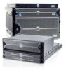
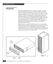
...-AL link control cards to manage the disks and provide an interface between the FC-AL and the drives. Disk Drive (0 - 14) Front Bezel Figure 1-1 DAE2 1-2 2-Gigabit Disk-Array Enclosure (DAE2) Hardware Reference Rackmount Cabinet EMC2164 The DAE2-ATA (Advanced Technology Attachment) version uses economical, high-capacity ATA disk drives and FC-to-ATA link control cards to manage them...
...-AL link control cards to manage the disks and provide an interface between the FC-AL and the drives. Disk Drive (0 - 14) Front Bezel Figure 1-1 DAE2 1-2 2-Gigabit Disk-Array Enclosure (DAE2) Hardware Reference Rackmount Cabinet EMC2164 The DAE2-ATA (Advanced Technology Attachment) version uses economical, high-capacity ATA disk drives and FC-to-ATA link control cards to manage them...

Hardware Reference
Page 17
... and support dual-port FC-AL interconnects through 1-4 show the disk enclosure components. Standard DAE2 disk modules are field-replaceable units (FRUs), which you cannot mix ATA and fibre components within a DAE2. ATA disk modules include dual-port ATA interconnects; Where the enclosure Introduction 1-3 You can place the disk enclosures in the same cabinet, or in one or more...
... and support dual-port FC-AL interconnects through 1-4 show the disk enclosure components. Standard DAE2 disk modules are field-replaceable units (FRUs), which you cannot mix ATA and fibre components within a DAE2. ATA disk modules include dual-port ATA interconnects; Where the enclosure Introduction 1-3 You can place the disk enclosures in the same cabinet, or in one or more...

Hardware Reference
Page 18
... in a rackmount cabinet as shown in the illustrations. Fault LED (Amber) Power LED (Green) Disk Activity LED (Green) Fault LED (Amber) EMC2166 Figure 1-2 DAE2 Front LED Display Figure 1-3 shows the DAE2 components visible from the rear of the rack cabinet. The enclosure status lights are called component-name... are visible with the front bezel installed. As shown in Figure 1-1. For increased clarity, the following figures depict the disk enclosure outside of the enclosure. About DAE2 Disk Enclosures provides slots for each disk module, and two disk enclosure status lights.
... in a rackmount cabinet as shown in the illustrations. Fault LED (Amber) Power LED (Green) Disk Activity LED (Green) Fault LED (Amber) EMC2166 Figure 1-2 DAE2 Front LED Display Figure 1-3 shows the DAE2 components visible from the rear of the rack cabinet. The enclosure status lights are called component-name... are visible with the front bezel installed. As shown in Figure 1-1. For increased clarity, the following figures depict the disk enclosure outside of the enclosure. About DAE2 Disk Enclosures provides slots for each disk module, and two disk enclosure status lights.

Hardware Reference
Page 19
... loop ID when the operating system loads. _ Enclosure 0 Address + 0 4 1 5 Loop ID 2 6 3 7 Figure 1-4 Disk Enclosure Rear Displays EMC2771 Introduction 1-5 About DAE2 Disk Enclosures Enclosure Address Switch Power/Cooling Module B Link Control Card B (LCC B) Power/Cooling Module A Link Control Card A (LCC A) Figure 1-3 Disk Enclosure Rear View EMC2770 As shown in Figure 1-3 and Figure 1-4, an enclosure address...
... loop ID when the operating system loads. _ Enclosure 0 Address + 0 4 1 5 Loop ID 2 6 3 7 Figure 1-4 Disk Enclosure Rear Displays EMC2771 Introduction 1-5 About DAE2 Disk Enclosures Enclosure Address Switch Power/Cooling Module B Link Control Card B (LCC B) Power/Cooling Module A Link Control Card A (LCC A) Figure 1-3 Disk Enclosure Rear View EMC2770 As shown in Figure 1-3 and Figure 1-4, an enclosure address...

Hardware Reference
Page 20
... 1-5, has a locking latch and an electromagnetic interference (EMI) shield. The front bezel, shown in the enclosure. Disk module IDs are numbered left to remove and install drive modules. Figure 1-5 Disk Enclosure Front Bezel 1-6 2-Gigabit Disk-Array Enclosure (DAE2) Hardware Reference EMC2173 enclosure 1 contains modules 15-29; The status lights are described in the installation...
... 1-5, has a locking latch and an electromagnetic interference (EMI) shield. The front bezel, shown in the enclosure. Disk module IDs are numbered left to remove and install drive modules. Figure 1-5 Disk Enclosure Front Bezel 1-6 2-Gigabit Disk-Array Enclosure (DAE2) Hardware Reference EMC2173 enclosure 1 contains modules 15-29; The status lights are described in the installation...

Hardware Reference
Page 21
...LCCs do not communicate with the last disk enclosure in the loop. Link Control Cards (LCCs) 1-7 The LCC passes the input signal to -point connections with or control each other Fibre Channel devices (processor enclosures, DAE2s, and so on its LCC. ATA link control cards provide the same Fibre... Link Control Cards (LCCs) An LCC supports and controls one Fibre Channel loop and monitors the DAE2. Each LCC independently monitors the environmental status of full-duplex, point-to the disk drives in Chapter 3. Each LCC has four status lights. Fault LED (Amber) Power LED (Green) ...
...LCCs do not communicate with the last disk enclosure in the loop. Link Control Cards (LCCs) 1-7 The LCC passes the input signal to -point connections with or control each other Fibre Channel devices (processor enclosures, DAE2s, and so on its LCC. ATA link control cards provide the same Fibre... Link Control Cards (LCCs) An LCC supports and controls one Fibre Channel loop and monitors the DAE2. Each LCC independently monitors the environmental status of full-duplex, point-to the disk drives in Chapter 3. Each LCC has four status lights. Fault LED (Amber) Power LED (Green) ...

