
Hardware Reference
Page 6
... Removing an LCC 3-15 Installing an LCC 3-16 Replacing a Power Supply/System Cooling Module 3-20 Appendix A Technical Specifications Enclosure Specifications A-2 Ac Power Requirements A-2 Size and Weight A-3 Drive Type A-3 LCC FC-AL Interface A-3 Standards Certification and Compliance A-4 Fibre Channel Related Standards A-4 Operating Limits A-5 Environmental Recovery A-5 Shipping and Storage Requirements A-6 Appendix B Customer Support Overview of Detecting and Resolving Problems B-2 Troubleshooting the Problem B-3 Before Calling the Customer Support Center B-4 Documenting...
... Removing an LCC 3-15 Installing an LCC 3-16 Replacing a Power Supply/System Cooling Module 3-20 Appendix A Technical Specifications Enclosure Specifications A-2 Ac Power Requirements A-2 Size and Weight A-3 Drive Type A-3 LCC FC-AL Interface A-3 Standards Certification and Compliance A-4 Fibre Channel Related Standards A-4 Operating Limits A-5 Environmental Recovery A-5 Shipping and Storage Requirements A-6 Appendix B Customer Support Overview of Detecting and Resolving Problems B-2 Troubleshooting the Problem B-3 Before Calling the Customer Support Center B-4 Documenting...

Hardware Reference
Page 7
... 3-11 Removing an LCC 3-16 2-Gigabit Disk-Array Enclosure (DAE2) Hardware Reference vii Two Fibre Channel Loops ......... 2-9 2-6 Cabling DAE2s Together - Four Fibre Channel Loops 2-10 2-7 Cabling Disk Enclosures Together - Figures Figure 1-1 DAE2 ...1-2 1-2 DAE2 Front LED Display 1-4 1-3 Disk Enclosure Rear View 1-5 1-4 Disk Enclosure Rear Displays 1-5 1-5 Disk Enclosure Front Bezel 1-6 1-6 LCC Connectors and LEDs 1-7 1-7 Disk Modules 1-8 1-8 Power/Cooling Module 1-9 2-1 Setting the Enclosure Address (EA 2-5 2-2 Plugging in the ac Line Cord 2-6 2-3 Connecting DAE2 Power Cords...
... 3-11 Removing an LCC 3-16 2-Gigabit Disk-Array Enclosure (DAE2) Hardware Reference vii Two Fibre Channel Loops ......... 2-9 2-6 Cabling DAE2s Together - Four Fibre Channel Loops 2-10 2-7 Cabling Disk Enclosures Together - Figures Figure 1-1 DAE2 ...1-2 1-2 DAE2 Front LED Display 1-4 1-3 Disk Enclosure Rear View 1-5 1-4 Disk Enclosure Rear Displays 1-5 1-5 Disk Enclosure Front Bezel 1-6 1-6 LCC Connectors and LEDs 1-7 1-7 Disk Modules 1-8 1-8 Power/Cooling Module 1-9 2-1 Setting the Enclosure Address (EA 2-5 2-2 Plugging in the ac Line Cord 2-6 2-3 Connecting DAE2 Power Cords...

Hardware Reference
Page 9
... Disk-Array Enclosure (DAE2) Hardware Reference ix Chapter 2, Installing a DAE2, describes how to be familiar with the following topics: ◆ Storage-system operation ◆ Basic computer hardware safety and maintenance procedures. Preface This manual is often called a disk enclosure. The DAE2 is your cabinet. Chapter 3, Servicing a DAE2, provides instructions and procedures for use Fibre Channel disks, and DAE2-ATA models that include Advanced Technology Attachment drives. Audience Organization This guide is part of the DAE2 documentation set...
... Disk-Array Enclosure (DAE2) Hardware Reference ix Chapter 2, Installing a DAE2, describes how to be familiar with the following topics: ◆ Storage-system operation ◆ Basic computer hardware safety and maintenance procedures. Preface This manual is often called a disk enclosure. The DAE2 is your cabinet. Chapter 3, Servicing a DAE2, provides instructions and procedures for use Fibre Channel disks, and DAE2-ATA models that include Advanced Technology Attachment drives. Audience Organization This guide is part of the DAE2 documentation set...

Hardware Reference
Page 12
... to Get Help To access EMC Powerlink, use the following : ◆ The FLARE™ software release notes ◆ The latest version of this guide. For questions about technical support and service, contact your storage system in , select Support > Document Library and find the following link: http://powerlink.emc.com After you log in a storage area network (SAN) or direct attach configuration. Please send a message to techpub_comments@emc...
... to Get Help To access EMC Powerlink, use the following : ◆ The FLARE™ software release notes ◆ The latest version of this guide. For questions about technical support and service, contact your storage system in , select Support > Document Library and find the following link: http://powerlink.emc.com After you log in a storage area network (SAN) or direct attach configuration. Please send a message to techpub_comments@emc...
Hardware Reference
Page 16
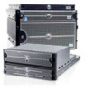
... hard disk drive/carrier modules. An enclosure connects to manage them. The examples and illustrations in this manual show the rackmounted DAE2 in RAID (Redundant Array of DAE2. EMC produces two types of Independent Disk) configurations. The DAE2-ATA (Advanced Technology Attachment) version uses economical, high-capacity ATA disk drives and FC-to-ATA link control cards to manage the disks and provide an interface between the FC-AL and the drives. Its modular, scalable design allows for additional disk storage...
... hard disk drive/carrier modules. An enclosure connects to manage them. The examples and illustrations in this manual show the rackmounted DAE2 in RAID (Redundant Array of DAE2. EMC produces two types of Independent Disk) configurations. The DAE2-ATA (Advanced Technology Attachment) version uses economical, high-capacity ATA disk drives and FC-to-ATA link control cards to manage the disks and provide an interface between the FC-AL and the drives. Its modular, scalable design allows for additional disk storage...

Hardware Reference
Page 17
... configurations use two, three, or four loops. Any unoccupied disk module slot has a filler module to fifteen 3.5-inch disk modules. ATA disk modules include dual-port ATA interconnects; The system can continue running correctly for continuous operation. About DAE2 Disk Enclosures Any DAE2 can support up . You can add or replace without tools while the array is powered up to maintain air flow. Where the enclosure Introduction 1-3 Highly available configurations require at least one operating power supply and...
... configurations use two, three, or four loops. Any unoccupied disk module slot has a filler module to fifteen 3.5-inch disk modules. ATA disk modules include dual-port ATA interconnects; The system can continue running correctly for continuous operation. About DAE2 Disk Enclosures Any DAE2 can support up . You can add or replace without tools while the array is powered up to maintain air flow. Where the enclosure Introduction 1-3 Highly available configurations require at least one operating power supply and...

Hardware Reference
Page 21
... disk drives in Chapter 3. Fault LED (Amber) Power LED (Green) Latch Loop ID LEDs Expansion Connector Expansion Link Active LED (Green) Primary Link Active LED (Green) Primary Connector EMC2165 Figure 1-6 LCC Connectors and LEDs The LCCs in a DAE2 are described in Monitoring Disk Enclosure Status in the enclosure; LCCs do not communicate with a long return from the ATA protocol used by their disk drives. The cabling is not explicitly configured as a set of the entire enclosure, using twin-axial copper cables...
... disk drives in Chapter 3. Fault LED (Amber) Power LED (Green) Latch Loop ID LEDs Expansion Connector Expansion Link Active LED (Green) Primary Link Active LED (Green) Primary Connector EMC2165 Figure 1-6 LCC Connectors and LEDs The LCCs in a DAE2 are described in Monitoring Disk Enclosure Status in the enclosure; LCCs do not communicate with a long return from the ATA protocol used by their disk drives. The cabling is not explicitly configured as a set of the entire enclosure, using twin-axial copper cables...

Hardware Reference
Page 22
... Disk-Array Enclosure (DAE2) Hardware Reference You can visually distinguish between module types by 3.5-inch (8.75 cm) disk drives. Disk Modules Each disk module consists of the carrier. Refer to either FC-AL or ATA 6 specifications, and either 1-Gbit and 2-Gbit Fibre Channel or 1.5-Gbit ATA interface standards. Fibre Channel disk modules will not work in use. Each carrier has a handle with the enclosure slot guides and midplane connectors. You can add or replace...
... Disk-Array Enclosure (DAE2) Hardware Reference You can visually distinguish between module types by 3.5-inch (8.75 cm) disk drives. Disk Modules Each disk module consists of the carrier. Refer to either FC-AL or ATA 6 specifications, and either 1-Gbit and 2-Gbit Fibre Channel or 1.5-Gbit ATA interface standards. Fibre Channel disk modules will not work in use. Each carrier has a handle with the enclosure slot guides and midplane connectors. You can add or replace...

Hardware Reference
Page 23
... affect the operation of the integrated blowers within two minutes. The leftmost LED indicates a failure in each module) fail, the DAE2 will go off switch. Each power/cooling module has three visible status lights. Each supply supports a fully configured DAE2 and shares load currents with power-related faults will speed up . The rightmost LED indicates power to the supply; About DAE2 Disk Enclosures The latch holds the disk module in place to ensure proper connection with...
... affect the operation of the integrated blowers within two minutes. The leftmost LED indicates a failure in each module) fail, the DAE2 will go off switch. Each power/cooling module has three visible status lights. Each supply supports a fully configured DAE2 and shares load currents with power-related faults will speed up . The rightmost LED indicates power to the supply; About DAE2 Disk Enclosures The latch holds the disk module in place to ensure proper connection with...

Hardware Reference
Page 26
... DAE2 disk enclosures. Typical values will interconnect. Power cords and supplies share the power load evenly. The site must meet the ambient temperature specification described in Appendix A. Cabling Requirements The DAE2 supports copper cable for example, a storage processor or another DAE2). Any copper cables you will be able to another Fibre Channel device (for a Fibre Channel connection to handle the BTU requirements of internally regulated power that you use a rackmount cabinet with High Speed Serial Data Connector...
... DAE2 disk enclosures. Typical values will interconnect. Power cords and supplies share the power load evenly. The site must meet the ambient temperature specification described in Appendix A. Cabling Requirements The DAE2 supports copper cable for example, a storage processor or another DAE2). Any copper cables you will be able to another Fibre Channel device (for a Fibre Channel connection to handle the BTU requirements of internally regulated power that you use a rackmount cabinet with High Speed Serial Data Connector...
Hardware Reference
Page 32
... device (storage processor or another DAE2) to the PRI connector in an Expansion-to Another FC Device 5. ATA enclosures do not support the boot and SPS requirements of the first disk array in Figure 2-5 shows a CLARiiON® CX500 disk processor enclosure (DPE2) below seven DAE2 disk-array enclosures. The configuration example in a storage system. 2-8 2-Gigabit Disk-Array Enclosure (DAE2) Hardware Reference EA 0, loop 0 must be a Fibre Channel DPE2 or DAE2. Installing a DAE2 4. If you are installing multiple disk enclosures, cable...
... device (storage processor or another DAE2) to the PRI connector in an Expansion-to Another FC Device 5. ATA enclosures do not support the boot and SPS requirements of the first disk array in Figure 2-5 shows a CLARiiON® CX500 disk processor enclosure (DPE2) below seven DAE2 disk-array enclosures. The configuration example in a storage system. 2-8 2-Gigabit Disk-Array Enclosure (DAE2) Hardware Reference EA 0, loop 0 must be a Fibre Channel DPE2 or DAE2. Installing a DAE2 4. If you are installing multiple disk enclosures, cable...

Hardware Reference
Page 36
... a storage processor (Enclosure Address 0, loop 0). 7. When you cannot change the EA while power is usually on . 2-12 2-Gigabit Disk-Array Enclosure (DAE2) Hardware Reference The same delays are normally on . The LCC hardware monitor (FRU monitor) resets and begins its FC-AL physical address only at least one LCC installed. Firmware commands can configure a driveless disk enclosure within a Fibre Channel loop. To avoid potential data loss, you must set the enclosure address...
... a storage processor (Enclosure Address 0, loop 0). 7. When you cannot change the EA while power is usually on . 2-12 2-Gigabit Disk-Array Enclosure (DAE2) Hardware Reference The same delays are normally on . The LCC hardware monitor (FRU monitor) resets and begins its FC-AL physical address only at least one LCC installed. Firmware commands can configure a driveless disk enclosure within a Fibre Channel loop. To avoid potential data loss, you must set the enclosure address...

Hardware Reference
Page 43
... the disk enclosure Fault light is powered up. Expansion Link Active 1 per supply Amber On when the power supply is faulty or is faulty. Flashing when either the LCC or a Fibre Channel connection is operating. If a fault light on a FRU remains on , examine the other status lights to the system. Servicing a DAE2 Figure 3-4 shows the status LEDs for the link control cards. Monitoring Disk Enclosure Status 3-5 Also on during Power On Self Test (POST). Power Supply Fault* 1 per LCC Green On when Expansion connection is...
... the disk enclosure Fault light is powered up. Expansion Link Active 1 per supply Amber On when the power supply is faulty or is faulty. Flashing when either the LCC or a Fibre Channel connection is operating. If a fault light on a FRU remains on , examine the other status lights to the system. Servicing a DAE2 Figure 3-4 shows the status LEDs for the link control cards. Monitoring Disk Enclosure Status 3-5 Also on during Power On Self Test (POST). Power Supply Fault* 1 per LCC Green On when Expansion connection is...
Hardware Reference
Page 49
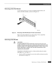
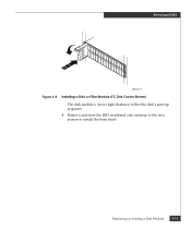
... Figure 3-6. Attach an ESD wristband to another slot can make information on the original LUN inaccessible. Replacing or Adding a Disk Module 3-11 EMC2210 Figure 3-6 Removing a Disk Filler Module (FC Disk Carrier Shown) Skip to the disk installation procedure (Page 3-12) to another slot unless you just emptied. Moving it was bound. Servicing a DAE2 Removing a Disk Filler Module Locate the slot where you should not remove a disk module unless its amber fault light is on. Removing a Disk Module !
... Figure 3-6. Attach an ESD wristband to another slot can make information on the original LUN inaccessible. Replacing or Adding a Disk Module 3-11 EMC2210 Figure 3-6 Removing a Disk Filler Module (FC Disk Carrier Shown) Skip to the disk installation procedure (Page 3-12) to another slot unless you just emptied. Moving it was bound. Servicing a DAE2 Removing a Disk Filler Module Locate the slot where you should not remove a disk module unless its amber fault light is on. Removing a Disk Module !
Hardware Reference
Page 51
Replacing or Adding a Disk Module 3-13 Remove and store the ESD wristband and continue to the next section to reflect the disk's spin-up sequence. 4. Servicing a DAE2 EMC2211 Figure 3-8 Installing a Disk or Filler Module (FC Disk Carrier Shown) The disk module's Active light flashes to install the front bezel.
Replacing or Adding a Disk Module 3-13 Remove and store the ESD wristband and continue to the next section to reflect the disk's spin-up sequence. 4. Servicing a DAE2 EMC2211 Figure 3-8 Installing a Disk or Filler Module (FC Disk Carrier Shown) The disk module's Active light flashes to install the front bezel.
Hardware Reference
Page 62
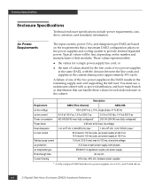
... DAE2 configuration places on the number and manufacturer of the two power supplies in the DAE2 results in the cabinet. Requirement ac line voltage ac line current Power consumption Power factor Heat dissipation In-rush current Startup surge current ac protection ac receptacle type Ride-through time Current sharing Description DAE2 (Fibre Channel) DAE2-ATA 100 to 240 V ac + 10%, single phase, 47 to provide internal regulated power...
... DAE2 configuration places on the number and manufacturer of the two power supplies in the DAE2 results in the cabinet. Requirement ac line voltage ac line current Power consumption Power factor Heat dissipation In-rush current Startup surge current ac protection ac receptacle type Ride-through time Current sharing Description DAE2 (Fibre Channel) DAE2-ATA 100 to 240 V ac + 10%, single phase, 47 to provide internal regulated power...

Hardware Reference
Page 63
... including mounting hardware 450 mm (17.72 in) 603.25 mm (23.75 in) 43.2 kg (95.3 lbs) maximum configuration 1.1 kg (2.4 lbs) per FC disk module; 1.125 kg (2.5 lbs) per ATA module 1.4 kg (3 lbs) per link control card 4.1 kg (9 lbs) per power supply 12.7 kg (28 lbs) chassis and midplane Drive Type The DAE2 uses 3.5-inch (8.75 cm) by 1.0-inch (2.54 cm) disk drives. and 5-volt and support the ATA-6 interface. Each drive slot...
... including mounting hardware 450 mm (17.72 in) 603.25 mm (23.75 in) 43.2 kg (95.3 lbs) maximum configuration 1.1 kg (2.4 lbs) per FC disk module; 1.125 kg (2.5 lbs) per ATA module 1.4 kg (3 lbs) per link control card 4.1 kg (9 lbs) per power supply 12.7 kg (28 lbs) chassis and midplane Drive Type The DAE2 uses 3.5-inch (8.75 cm) by 1.0-inch (2.54 cm) disk drives. and 5-volt and support the ATA-6 interface. Each drive slot...
Hardware Reference
Page 68
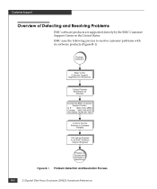
... Problem is Software Related Call will be Directed to an EMC Software Support Engineer Problem is Tracked and Managed to resolve customer problems with its software products (Figure B-1). Customer Support Overview of Detecting and Resolving Problems EMC software products are supported directly by the EMC Customer Support Center in the United States. EMC uses the following process to Resolution Figure B-1 Problem Detection and Resolution Process B-2 2-Gigabit Disk-Array Enclosure (DAE2) Hardware...
... Problem is Software Related Call will be Directed to an EMC Software Support Engineer Problem is Tracked and Managed to resolve customer problems with its software products (Figure B-1). Customer Support Overview of Detecting and Resolving Problems EMC software products are supported directly by the EMC Customer Support Center in the United States. EMC uses the following process to Resolution Figure B-1 Problem Detection and Resolution Process B-2 2-Gigabit Disk-Array Enclosure (DAE2) Hardware...

Hardware Reference
Page 70
...; Your phone number ❑ For an existing problem, the problem tracking system ID, if one was previously assigned to the problem by a support representative ❑ For an MVS problem, the JESLOG, SYSPRINT, all STDOUT DD members of the server job output and similar output for the client, and the relevant portion of the SYSLOG B-4 2-Gigabit Disk-Array Enclosure (DAE2) Hardware Reference
...; Your phone number ❑ For an existing problem, the problem tracking system ID, if one was previously assigned to the problem by a support representative ❑ For an MVS problem, the JESLOG, SYSPRINT, all STDOUT DD members of the server job output and similar output for the client, and the relevant portion of the SYSLOG B-4 2-Gigabit Disk-Array Enclosure (DAE2) Hardware Reference

Hardware Reference
Page 76
... 3-15 power issues 3-6 power supply adding 3-20 description 1-9 replacing 3-20 storing 3-6 H help xii hot spare, restrictions 2-13 I indicators, ID 3-4 installation requirements 2-2 installing DAE2 in cabinet 2-3 disk filler modules 3-12 L LCC (link control card) adding 3-15 cabling A-3 DAE2 to DAE2 3-19 requirements 2-2 description 1-7 FC-AL connector A-3 reattaching cables to 3-18 removing copper cables 3-15 replacing 3-15 status light, Active 3-5 status lights 1-7 lights, DAE2 status 3-2 lithium backup battery, disposing of safely xiv i-2 2-Gigabit Disk-Array Enclosure (DAE2) Hardware...
... 3-15 power issues 3-6 power supply adding 3-20 description 1-9 replacing 3-20 storing 3-6 H help xii hot spare, restrictions 2-13 I indicators, ID 3-4 installation requirements 2-2 installing DAE2 in cabinet 2-3 disk filler modules 3-12 L LCC (link control card) adding 3-15 cabling A-3 DAE2 to DAE2 3-19 requirements 2-2 description 1-7 FC-AL connector A-3 reattaching cables to 3-18 removing copper cables 3-15 replacing 3-15 status light, Active 3-5 status lights 1-7 lights, DAE2 status 3-2 lithium backup battery, disposing of safely xiv i-2 2-Gigabit Disk-Array Enclosure (DAE2) Hardware...

