
Setup Guide
Page 2
...THIS PUBLICATION, AND SPECIFICALLY DISCLAIMS IMPLIED WARRANTIES OF MERCHANTABILITY OR FITNESS FOR A PARTICULAR PURPOSE. However, the information is accurate as of any EMC software described in this publication require an applicable software license. THE ...INFORMATION IN THIS PUBLICATION IS PROVIDED "AS IS." All other trademarks mentioned herein are trademarks of their respective owners. Printed July, 2002 EMC believes the information in this publication is subject to change without notice. Use...
...THIS PUBLICATION, AND SPECIFICALLY DISCLAIMS IMPLIED WARRANTIES OF MERCHANTABILITY OR FITNESS FOR A PARTICULAR PURPOSE. However, the information is accurate as of any EMC software described in this publication require an applicable software license. THE ...INFORMATION IN THIS PUBLICATION IS PROVIDED "AS IS." All other trademarks mentioned herein are trademarks of their respective owners. Printed July, 2002 EMC believes the information in this publication is subject to change without notice. Use...

Setup Guide
Page 3
... Disk Array Enclosures (DAE2s) up and running. Once logged in to Powerlink, select Services, then Document Library, CLARiiON, CLARiiON Fibre Channel Storage (FC) and then CLARiiON FC Hardware, CLARiiON FC Core Software, or CLARiiON FC Software for lists and .pdf versions of DAE2 documentation are configuring the 3U enclosure as a disk array for a storage processing device (such as you perform the following tasks: • Set DAE2 Enclosure Address(es) • Set Up...
... Disk Array Enclosures (DAE2s) up and running. Once logged in to Powerlink, select Services, then Document Library, CLARiiON, CLARiiON Fibre Channel Storage (FC) and then CLARiiON FC Hardware, CLARiiON FC Core Software, or CLARiiON FC Software for lists and .pdf versions of DAE2 documentation are configuring the 3U enclosure as a disk array for a storage processing device (such as you perform the following tasks: • Set DAE2 Enclosure Address(es) • Set Up...
Setup Guide
Page 4
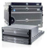
... already installed in a rackmount cabinet ❑ One or more rails kits, and the ❑ EMC Storage Systems 40U Cabinet Configuration Guide (P/N 014003082) ❑ Fibre Channel copper cable for connecting the DAE2 to a storage processor device (1 per connection) ❑ Copper cables for Basic Configuration Before you start, be sure you will use EMC Control Center™ Navisphere® to each other (2 per DAE2) ❑ EMC 2-Gigabit Disk Enclosure (DAE2) Hardware...
... already installed in a rackmount cabinet ❑ One or more rails kits, and the ❑ EMC Storage Systems 40U Cabinet Configuration Guide (P/N 014003082) ❑ Fibre Channel copper cable for connecting the DAE2 to a storage processor device (1 per connection) ❑ Copper cables for Basic Configuration Before you start, be sure you will use EMC Control Center™ Navisphere® to each other (2 per DAE2) ❑ EMC 2-Gigabit Disk Enclosure (DAE2) Hardware...

Setup Guide
Page 5
... Manager version 6.1 or higher is not already installed in the cabinet and set up . If you will use EMC ControlCenter Navisphere Manager to install a 3U device like the DAE2 in place at your DAE2 is set up . You can add DAE2 enclosures to the Setup Guide or Hardware Reference for the device. 3. If your facility. The EMC Storage Systems 40U Cabinet Configuration Guide describes how to monitor DAE2 status...
... Manager version 6.1 or higher is not already installed in the cabinet and set up . If you will use EMC ControlCenter Navisphere Manager to install a 3U device like the DAE2 in place at your DAE2 is set up . You can add DAE2 enclosures to the Setup Guide or Hardware Reference for the device. 3. If your facility. The EMC Storage Systems 40U Cabinet Configuration Guide describes how to monitor DAE2 status...
Setup Guide
Page 6
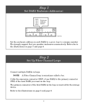
... first DAE2 in the loop is sometimes called a bus. Step 2 Set Up Fibre Channel Loops Connect multiple DAE2s in loops. The primary connector of the next DAE2 you number enclosures consecutively. We strongly suggest that you want on the loop. Step 1 Set DAE2 Enclosure Address(es) _ Enclosure 0 Address + Switch EMC2310 Set the enclosure address on each DAE2 in a given loop to...
... first DAE2 in the loop is sometimes called a bus. Step 2 Set Up Fibre Channel Loops Connect multiple DAE2s in loops. The primary connector of the next DAE2 you number enclosures consecutively. We strongly suggest that you want on the loop. Step 1 Set DAE2 Enclosure Address(es) _ Enclosure 0 Address + Switch EMC2310 Set the enclosure address on each DAE2 in a given loop to...
Setup Guide
Page 7
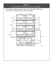
Loop 0 LCC B LCC A EA1/Loop 1 Loop 0 Loop 1 Loop 0 Loop 1 Loop 0 EA1/Loop 0 EA0/Loop 1 EA0/Loop 0 EXP PRI EXP PRI BE1 BE0 SP B SPE SP A BE0 BE1 Loop 1 Loop 0 Loop 1 Loop 0 EMC2311 5 Step 2 Set Up Fibre Channel Loops (continued) The example configuration below shows two redundant DAE2 loops connected to a Storage Processor Enclosure (SPE).
Loop 0 LCC B LCC A EA1/Loop 1 Loop 0 Loop 1 Loop 0 Loop 1 Loop 0 EA1/Loop 0 EA0/Loop 1 EA0/Loop 0 EXP PRI EXP PRI BE1 BE0 SP B SPE SP A BE0 BE1 Loop 1 Loop 0 Loop 1 Loop 0 EMC2311 5 Step 2 Set Up Fibre Channel Loops (continued) The example configuration below shows two redundant DAE2 loops connected to a Storage Processor Enclosure (SPE).
Setup Guide
Page 8
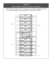
LCC B Loop 0 SPS B Loop 1 EA4/Loop 0 LCC A EA3/Loop 0 EA2/Loop 0 EA1/Loop 0 Loop 0 EA0/Loop 0 SP B SP A EA0/Loop 1 SPS A EA1/Loop 1 EA2/Loop 1 Loop 1 EA3/Loop 1 EA4/Loop 1 EXP PRI EMC2351 6 Step 2 Set Up Fibre Channel Loops (continued) The illustration below shows an example storage-system configuration with two redundant DAE2 loops segregated above and below the SPE.
LCC B Loop 0 SPS B Loop 1 EA4/Loop 0 LCC A EA3/Loop 0 EA2/Loop 0 EA1/Loop 0 Loop 0 EA0/Loop 0 SP B SP A EA0/Loop 1 SPS A EA1/Loop 1 EA2/Loop 1 Loop 1 EA3/Loop 1 EA4/Loop 1 EXP PRI EMC2351 6 Step 2 Set Up Fibre Channel Loops (continued) The illustration below shows an example storage-system configuration with two redundant DAE2 loops segregated above and below the SPE.
Setup Guide
Page 9
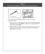
b. Plug one end of the cables into the primary (PRI) High Speed Serial Data Connector (HSSDC) connector on the storage device. Plug the other FC device EMC2312 1. Refer to a storage processing device a. Step 3 Connect the DAE2 to a Storage Processing Device PRI Connector To other end of a copper cable into the appropriate connector on each Link Control Card (LCC) in a loop to the Setup Guide or the Hardware Reference for the device. 7 If you are connecting the first DAE2 in the DAE2.
b. Plug one end of the cables into the primary (PRI) High Speed Serial Data Connector (HSSDC) connector on the storage device. Plug the other FC device EMC2312 1. Refer to a storage processing device a. Step 3 Connect the DAE2 to a Storage Processing Device PRI Connector To other end of a copper cable into the appropriate connector on each Link Control Card (LCC) in a loop to the Setup Guide or the Hardware Reference for the device. 7 If you are connecting the first DAE2 in the DAE2.
Setup Guide
Page 10
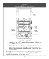
... power supplies to a secondary power supply (SPS). 8 The highly available configuration example shown above supports write caching. Connect one end of each DAE2 power supply. 2. It has two power strips and an SPE, and the first DAE2 is connected to opposing side power strips so they do not share a single circuit. Connect the other end of an ac power cable to the power connector on each ac power cable...
... power supplies to a secondary power supply (SPS). 8 The highly available configuration example shown above supports write caching. Connect one end of each DAE2 power supply. 2. It has two power strips and an SPE, and the first DAE2 is connected to opposing side power strips so they do not share a single circuit. Connect the other end of an ac power cable to the power connector on each ac power cable...
Setup Guide
Page 11
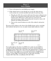
... DAE2 Hardware Reference. an amber chassis light indicates a fault. Fault LED (Amber) Power LED (Green) Disk Activity LED (Green) Fault LED (Amber) EMC2166 If an amber light on the front of the cabinet's side power strips. Then refer to the fault code explanations in Chapter 3 of a DAE2 is lit, make sure the DAE2 is on; We recommend connecting each disk drive indicate that power is correctly cabled, the enclosure addresses are correct, and the disks are correctly installed...
... DAE2 Hardware Reference. an amber chassis light indicates a fault. Fault LED (Amber) Power LED (Green) Disk Activity LED (Green) Fault LED (Amber) EMC2166 If an amber light on the front of the cabinet's side power strips. Then refer to the fault code explanations in Chapter 3 of a DAE2 is lit, make sure the DAE2 is on; We recommend connecting each disk drive indicate that power is correctly cabled, the enclosure addresses are correct, and the disks are correctly installed...

Setup Guide
Page 12
... Use this resource Find it here • Storage-system configurations • Configuration planning EMC Fibre Channel Storage System CX-Series Configuration and Planning Guide • Hardware component installation or maintenance EMC 2-Gigabit Disk Enclosure (DAE2) Hardware Reference Storage Processor Hardware Reference(s) as appropriate. • Managing the storage system EMC ControlCenter Navisphere Manager Revision 6.X Administrator's Guide and release notes • Last minute changes to Powerlink, select Services > Document Library > CLARiiON > CLARiiON Fibre Channel Storage...
... Use this resource Find it here • Storage-system configurations • Configuration planning EMC Fibre Channel Storage System CX-Series Configuration and Planning Guide • Hardware component installation or maintenance EMC 2-Gigabit Disk Enclosure (DAE2) Hardware Reference Storage Processor Hardware Reference(s) as appropriate. • Managing the storage system EMC ControlCenter Navisphere Manager Revision 6.X Administrator's Guide and release notes • Last minute changes to Powerlink, select Services > Document Library > CLARiiON > CLARiiON Fibre Channel Storage...

Setup Guide
Page 13
For questions about technical support and service, contact your local sales office. 11 For questions about upgrades, contact your service provider. If You Need Help . If you have an EMC service contract, contact EMC Customer Service at USA (800) 782-4362, Canada (800) 543-4782, or worldwide (508) 497-7901.
For questions about technical support and service, contact your local sales office. 11 For questions about upgrades, contact your service provider. If You Need Help . If you have an EMC service contract, contact EMC Customer Service at USA (800) 782-4362, Canada (800) 543-4782, or worldwide (508) 497-7901.


