Manual
Page 3
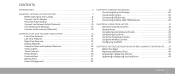
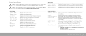
...3: CONNECTING DEVICES 25 Connecting External Displays 26 Connecting Printers 28 Connecting USB Devices 29 Connecting FireWire (IEEE 1394) Devices 29 CHAPTER 4: USING YOUR LAPTOP 31 Alienware Command Center 32 Stealth Mode 32 Using Removable Media and Cards 32 Using the Optical Drive 33 Using the Integrated Camera 33 Using the Wireless... 33 Configuring the BIOS 34 CHAPTER 5: INSTALLING ADDITIONAL OR REPLACEMENT COMPONENTS . . . . . 41 Before You Begin 42 Replacing the Battery Pack 44 Upgrading or Replacing Memory 45 Upgrading or Replacing the Hard Drive 47 CONTENTS 3
...3: CONNECTING DEVICES 25 Connecting External Displays 26 Connecting Printers 28 Connecting USB Devices 29 Connecting FireWire (IEEE 1394) Devices 29 CHAPTER 4: USING YOUR LAPTOP 31 Alienware Command Center 32 Stealth Mode 32 Using Removable Media and Cards 32 Using the Optical Drive 33 Using the Integrated Camera 33 Using the Wireless... 33 Configuring the BIOS 34 CHAPTER 5: INSTALLING ADDITIONAL OR REPLACEMENT COMPONENTS . . . . . 41 Before You Begin 42 Replacing the Battery Pack 44 Upgrading or Replacing Memory 45 Upgrading or Replacing the Hard Drive 47 CONTENTS 3
Manual
Page 16
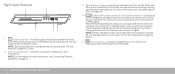
... information on audio connectors, see "Using the Optical Drive " on page 33. 4 USB/eSATA combo connector with print or writing is designed only for additional memory, wired and wireless communications, multimedia, and security features. NOTE: The ExpressCard slot is facing upward when inserting discs. Right View Features 1 2 3 45 1 ExpressCard slot - For...
... information on audio connectors, see "Using the Optical Drive " on page 33. 4 USB/eSATA combo connector with print or writing is designed only for additional memory, wired and wireless communications, multimedia, and security features. NOTE: The ExpressCard slot is facing upward when inserting discs. Right View Features 1 2 3 45 1 ExpressCard slot - For...
Manual
Page 34
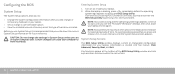
... (or restart) your laptop. 2. Key functions appear at the bottom of time. CAUTION: Do not change a user-selectable option. • View the installed amount of memory or set the type of hard drive installed. NOTE: If you wait too long and the operating system logo appears, continue to work incorrectly. Information...
... (or restart) your laptop. 2. Key functions appear at the bottom of time. CAUTION: Do not change a user-selectable option. • View the installed amount of memory or set the type of hard drive installed. NOTE: If you wait too long and the operating system logo appears, continue to work incorrectly. Information...
Manual
Page 35
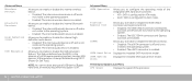
... of the processor. Allows you to the operating system. • Enabled: Internal LAN is enabled. Main Menu System Time System Date Alienware Service Tag BIOS Version EC Version CPU CPU Speed CPU Cache CPU ID Displays the system time. Displays the processor cache size. CHAPTER ...type of your computer. Displays the system date. Allows you to enable or disable the on the Dell Support website at support.dell.com/manuals. Displays the memory size installed in memory bank 0. Allows you to enable or disable the diagnostic screen during boot. Displays the BIOS revision....
... of the processor. Allows you to the operating system. • Enabled: Internal LAN is enabled. Main Menu System Time System Date Alienware Service Tag BIOS Version EC Version CPU CPU Speed CPU Cache CPU ID Displays the system time. Displays the processor cache size. CHAPTER ...type of your computer. Displays the system date. Allows you to enable or disable the on the Dell Support website at support.dell.com/manuals. Displays the memory size installed in memory bank 0. Allows you to enable or disable the diagnostic screen during boot. Displays the BIOS revision....
Manual
Page 36
... operating system. • Enabled: The eSATA connector is enabled. Performance Options Sub-Menu CPU Speed Displays the speed of USB device (floppy, hard drive, or memory key) when this option is off and is not visible to enable or disable the USB emulation feature. Displays the installed SATA optical drive model...
... operating system. • Enabled: The eSATA connector is enabled. Performance Options Sub-Menu CPU Speed Displays the speed of USB device (floppy, hard drive, or memory key) when this option is off and is not visible to enable or disable the USB emulation feature. Displays the installed SATA optical drive model...
Manual
Page 37
... enable or disable password entry on Boot Asset Tag Displays if the supervisor password is clear or set the memory frequency. Allows you to set the user password. Memory Channel Mode Displays the memory channel modes. • Single • Dual CPU Performance Indicates if the processor is set . Note: ...only if the clock mode is in turbo mode or not. Displays the asset tag. Mode Turbo Mode Allows you to choose the FSB-memory system clock mode. Allows you to set the supervisor password. Allows you to enable or disable the turbo mode. The user password controls ...
... enable or disable password entry on Boot Asset Tag Displays if the supervisor password is clear or set the memory frequency. Allows you to set the user password. Memory Channel Mode Displays the memory channel modes. • Single • Dual CPU Performance Indicates if the processor is set . Note: ...only if the clock mode is in turbo mode or not. Displays the asset tag. Mode Turbo Mode Allows you to choose the FSB-memory system clock mode. Allows you to set the supervisor password. Allows you to enable or disable the turbo mode. The user password controls ...
Manual
Page 45
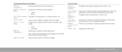
...(s) 1. The table below illustrates all the possible ways system memory can be configured. Memory connector #1 1 GB 2 GB 1 GB 2 GB 4 GB Memory connector #2 1 GB 1 GB 2 GB 2 GB 4 GB Total Memory 2 GB 3 GB 3 GB 4 GB 8 GB 21 1 screws (2) 2 compartment door CHAPTER 5: INSTALLING ADDITIONAL OR REPLACEMENT COMPONENTS 45 Follow the instructions in "Before You Begin" on page...
...(s) 1. The table below illustrates all the possible ways system memory can be configured. Memory connector #1 1 GB 2 GB 1 GB 2 GB 4 GB Memory connector #2 1 GB 1 GB 2 GB 2 GB 4 GB Total Memory 2 GB 3 GB 3 GB 4 GB 8 GB 21 1 screws (2) 2 compartment door CHAPTER 5: INSTALLING ADDITIONAL OR REPLACEMENT COMPONENTS 45 Follow the instructions in "Before You Begin" on page...

Manual
Page 46
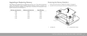
... the bottom connector and then in reverse order. 3. Remove the memory module. 46 CHAPTER 5: INSTALLING ADDITIONAL OR REPLACEMENT COMPONENTS 5 4 1 memory module connector 2 notch 3 tab 4 spring locks (2) 5 memory module To replace the memory modules, perform the removal steps in the top connector. NOTE: If the memory module is not installed properly, the computer may not boot...
... the bottom connector and then in reverse order. 3. Remove the memory module. 46 CHAPTER 5: INSTALLING ADDITIONAL OR REPLACEMENT COMPONENTS 5 4 1 memory module connector 2 notch 3 tab 4 spring locks (2) 5 memory module To replace the memory modules, perform the removal steps in the top connector. NOTE: If the memory module is not installed properly, the computer may not boot...

Manual
Page 51
..., answer any computer components were added or removed before troubleshooting: • Ensure that failed, press . • If failures are experiencing memory issues, press else press . To stop the assessment and restart the computer, press ; If the Pre-boot System Assessment completes successfully, the following...check to see if you are detected during the Pre-boot System Assessment, write down the exact error message prior to calling Alienware Technical Support to retest the component that the AC adapter cable is displayed: "Pre-boot System Assessment complete." Doing so will...
..., answer any computer components were added or removed before troubleshooting: • Ensure that failed, press . • If failures are experiencing memory issues, press else press . To stop the assessment and restart the computer, press ; If the Pre-boot System Assessment completes successfully, the following...check to see if you are detected during the Pre-boot System Assessment, write down the exact error message prior to calling Alienware Technical Support to retest the component that the AC adapter cable is displayed: "Pre-boot System Assessment complete." Doing so will...
Manual
Page 57
... Display If the display is recommended that you are using a dual-channel memory configuration require that requires a higher resolution than your computer. Memory Memory errors detected on . Connect the computer to resume normal operation. Reseat the memory modules if applicable (see "CONTACTING ALIENWARE" on the keyboard or press the power button to an electrical outlet...
... Display If the display is recommended that you are using a dual-channel memory configuration require that requires a higher resolution than your computer. Memory Memory errors detected on . Connect the computer to resume normal operation. Reseat the memory modules if applicable (see "CONTACTING ALIENWARE" on the keyboard or press the power button to an electrical outlet...
Manual
Page 68
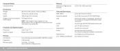
... two internally-accessible DDR3 SODIMM sockets 2 GB to 8 GB 1067 MHz, 1333 MHz (dual channel configurations) 68 CHAPTER 8: BASIC SPECIFICATIONS Memory Memory configurations possible 2 GB, 3 GB, 4 GB, and 8 GB Ports and Connectors IEEE 1394 A Network adapter USB eSATA VGA DisplayPort Audio...-hole connector one 20-pin connector one microphone connector, two stereo headphone/speaker connectors one ExpressCard/54 connector one combo connector Computer Model Alienware M15x Dimensions Height Width Depth Weight with 6-cell battery (starting at) 48.7 mm (1.92 inches) - Front and Back 377.93 mm...
... two internally-accessible DDR3 SODIMM sockets 2 GB to 8 GB 1067 MHz, 1333 MHz (dual channel configurations) 68 CHAPTER 8: BASIC SPECIFICATIONS Memory Memory configurations possible 2 GB, 3 GB, 4 GB, and 8 GB Ports and Connectors IEEE 1394 A Network adapter USB eSATA VGA DisplayPort Audio...-hole connector one 20-pin connector one microphone connector, two stereo headphone/speaker connectors one ExpressCard/54 connector one combo connector Computer Model Alienware M15x Dimensions Height Width Depth Weight with 6-cell battery (starting at) 48.7 mm (1.92 inches) - Front and Back 377.93 mm...

Manual
Page 69
... card (full card slot) Discs/Cards Supported Optical drive formats Reader card types SATA-compliant Blu-ray Disc, DVD-RW combo • Secure Digital (SD) memory card • Secure Digital High Capacity (SDHC) card • Secure Digital Input/Output (SDIO) card • Multi Media Card (MMC) •...
... card (full card slot) Discs/Cards Supported Optical drive formats Reader card types SATA-compliant Blu-ray Disc, DVD-RW combo • Secure Digital (SD) memory card • Secure Digital High Capacity (SDHC) card • Secure Digital Input/Output (SDIO) card • Multi Media Card (MMC) •...
Comprehensive Specifications
Page 4
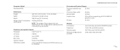
... data width 64 bits BIOS EPROM 16 Mbit Graphics bus PCIe x16 bus supporting x16 PCIe MXM 3.0 graphics cards PCI bus 32 bits Memory Connectors Capacities Memory types Memory configurations possible two internally-accessible SODIMM sockets 1 GB, 2 GB, and 4 GB modules 1067 MHz and 1333 MHz DDR3 2 GB,...weight of DDR3 memory up to 8 MB Bus clock 133 MHz System chipset Mobile Intel PM55 SDRAM bus width one or two 64-bit channels of your laptop will vary depending on the configuration ordered and the manufacturing variability. Computer Model Alienware M15x Dimensions Height Width ...
... data width 64 bits BIOS EPROM 16 Mbit Graphics bus PCIe x16 bus supporting x16 PCIe MXM 3.0 graphics cards PCI bus 32 bits Memory Connectors Capacities Memory types Memory configurations possible two internally-accessible SODIMM sockets 1 GB, 2 GB, and 4 GB modules 1067 MHz and 1333 MHz DDR3 2 GB,...weight of DDR3 memory up to 8 MB Bus clock 133 MHz System chipset Mobile Intel PM55 SDRAM bus width one or two 64-bit channels of your laptop will vary depending on the configuration ordered and the manufacturing variability. Computer Model Alienware M15x Dimensions Height Width ...
Comprehensive Specifications
Page 5
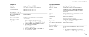
... mm) ExpressCard/34 (34 mm) ExpressCard/54 (54 mm) Ricoh R5C833 compliant with standard IEE1394a-2000 specification • Secure Digital (SD) memory card • Secure Digital High Capacity (SDHC) card • Secure Digital Input/Output (SDIO) card • Multi Media Card (MMC) •...; Memory Stick • Memory Stick PRO • xD-Picture Card (type - ExpressCard Interface Connector Cards supported IEEE 1394/Media Card IEEE 1394/Media Card controller IEEE 1394...
... mm) ExpressCard/34 (34 mm) ExpressCard/54 (54 mm) Ricoh R5C833 compliant with standard IEE1394a-2000 specification • Secure Digital (SD) memory card • Secure Digital High Capacity (SDHC) card • Secure Digital Input/Output (SDIO) card • Multi Media Card (MMC) •...; Memory Stick • Memory Stick PRO • xD-Picture Card (type - ExpressCard Interface Connector Cards supported IEEE 1394/Media Card IEEE 1394/Media Card controller IEEE 1394...

Service Manual
Page 3
... 14 Replacing the Compartment Door 14 CHAPTER 4: HARD DRIVE 15 Removing the Hard Drive 17 Replacing the Hard Drive 18 CHAPTER 5: MEMORY MODULE(S 19 Removing the Memory Module(s 21 Replacing the Memory Module(s 23 CONTENTS CHAPTER 6: COIN-CELL BATTERY 25 Removing the Coin-Cell Battery 27 Replacing the Coin-Cell Battery 27...
... 14 Replacing the Compartment Door 14 CHAPTER 4: HARD DRIVE 15 Removing the Hard Drive 17 Replacing the Hard Drive 18 CHAPTER 5: MEMORY MODULE(S 19 Removing the Memory Module(s 21 Replacing the Memory Module(s 23 CONTENTS CHAPTER 6: COIN-CELL BATTERY 25 Removing the Coin-Cell Battery 27 Replacing the Coin-Cell Battery 27...
Service Manual
Page 19
... purchased from the bottom of the computer. 019 /019 Install only memory modules that can increase your computer. CHAPTER 5: MEMORY MODULE(S) CHAPTER 5: MEMORY MODULE(S) CHAPTER 5: MEMORY MODULE(S) You can be accessed from Dell or Alienware are supported by your computer memory by installing memory modules on the memory supported by your computer warranty. Your computer has two user-accessible...
... purchased from the bottom of the computer. 019 /019 Install only memory modules that can increase your computer. CHAPTER 5: MEMORY MODULE(S) CHAPTER 5: MEMORY MODULE(S) CHAPTER 5: MEMORY MODULE(S) You can be accessed from Dell or Alienware are supported by your computer memory by installing memory modules on the memory supported by your computer warranty. Your computer has two user-accessible...
Service Manual
Page 20
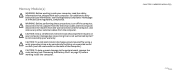
Damage due to the system board, remove the main battery (see the Regulatory Compliance Homepage at www.dell.com/regulatory_compliance. CHAPTER 5: MEMORY MODULE(S) 020 /020 CAUTION: Only a certified service technician should perform repairs on the back of the computer). WARNING: ..., see "Removing the Battery Pack" on page 11) before working inside the computer. Memory Module(s) WARNING: Before working inside your computer, read the safety information that is not authorized by Dell™ is not covered by periodically touching an unpainted metal surface (such as a connector...
Damage due to the system board, remove the main battery (see the Regulatory Compliance Homepage at www.dell.com/regulatory_compliance. CHAPTER 5: MEMORY MODULE(S) 020 /020 CAUTION: Only a certified service technician should perform repairs on the back of the computer). WARNING: ..., see "Removing the Battery Pack" on page 11) before working inside the computer. Memory Module(s) WARNING: Before working inside your computer, read the safety information that is not authorized by Dell™ is not covered by periodically touching an unpainted metal surface (such as a connector...
Service Manual
Page 21
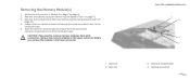
... to the computer base. 5. Remove the battery pack (see "Removing the Compartment Door" on page 14). 4. Removing the Memory Module(s) 1. CAUTION: If you need to remove memory modules from both connectors, remove the memory module in the upper connector before you remove the module in "Before You Begin" on page 11). 3. Remove the...
... to the computer base. 5. Remove the battery pack (see "Removing the Compartment Door" on page 14). 4. Removing the Memory Module(s) 1. CAUTION: If you need to remove memory modules from both connectors, remove the memory module in the upper connector before you remove the module in "Before You Begin" on page 11). 3. Remove the...
Service Manual
Page 22
CAUTION: To prevent damage to the memory module connector(s), do not use tools to carefully spread apart the spring-locks on the memory-module connector until the memory module pops up. 7. Remove the memory module. 2 1 memory module 2 spring-locks (2) CHAPTER 5: MEMORY MODULE(S) 5 4 1 3 memory-module connector 022 /022 Use your fingertips to spread the memory module spring-locks. 3 6.
CAUTION: To prevent damage to the memory module connector(s), do not use tools to carefully spread apart the spring-locks on the memory-module connector until the memory module pops up. 7. Remove the memory module. 2 1 memory module 2 spring-locks (2) CHAPTER 5: MEMORY MODULE(S) 5 4 1 3 memory-module connector 022 /022 Use your fingertips to spread the memory module spring-locks. 3 6.

Service Manual
Page 23
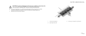
... door to close may not boot. 023 /023 Align the notch on the memory module with the tab on page 6. 2. Replacing the Memory Module(s) CAUTION: If you need to install memory modules in two connectors, install a memory module in the lower connector before you do not hear the click, remove the module and reinstall...
... door to close may not boot. 023 /023 Align the notch on the memory module with the tab on page 6. 2. Replacing the Memory Module(s) CAUTION: If you need to install memory modules in two connectors, install a memory module in the lower connector before you do not hear the click, remove the module and reinstall...


