
Comprehensive Specifications
Page 8
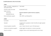
COMPREHENSIVE SPECIFICATIONS Video Video controller integrated on Intel GS45 the system board Discrete video controller Nvidia NV11P-GS1 Video memory Intel GS45 Nvidia NV11P-GS1 dynamic based on system memory capacity 1 GB External display support VGA, HDMI, and DisplayPort Audio Controller Speaker Internal speaker amplifier Internal microphone support Volume controls Realtek ALC665 single 8-ohms speakers in camera assembly program menus and media keyboard function keys 8 up to 2 W total power single digital microphone in both the left and right speaker assembly...
COMPREHENSIVE SPECIFICATIONS Video Video controller integrated on Intel GS45 the system board Discrete video controller Nvidia NV11P-GS1 Video memory Intel GS45 Nvidia NV11P-GS1 dynamic based on system memory capacity 1 GB External display support VGA, HDMI, and DisplayPort Audio Controller Speaker Internal speaker amplifier Internal microphone support Volume controls Realtek ALC665 single 8-ohms speakers in camera assembly program menus and media keyboard function keys 8 up to 2 W total power single digital microphone in both the left and right speaker assembly...
Comprehensive Specifications
Page 9
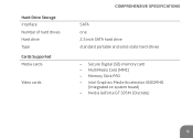
Hard-Drive Storage Interface Number of hard drives Hard drive Type Cards Supported Media cards Video cards COMPREHENSIVE SPECIFICATIONS SATA one 2.5 inch SATA hard drive standard portable and solid-state hard-drives • Secure Digital (SD) memory card • MultiMedia Card (MMC) • Memory Stick PRO • Intel Graphics Media Accelerator 4500MHD (Integrated on system board) • Nvidia GeForce GT 335M (Discrete) 9
Hard-Drive Storage Interface Number of hard drives Hard drive Type Cards Supported Media cards Video cards COMPREHENSIVE SPECIFICATIONS SATA one 2.5 inch SATA hard drive standard portable and solid-state hard-drives • Secure Digital (SD) memory card • MultiMedia Card (MMC) • Memory Stick PRO • Intel Graphics Media Accelerator 4500MHD (Integrated on system board) • Nvidia GeForce GT 335M (Discrete) 9

COMPREHENSIVE SPECIFICATIONS
Page 8
COMPREHENSIVE SPECIFICATIONS Video Video controller integrated on Intel GS45 the system board Discrete video controller Nvidia NV11P-GS1 Video memory Intel GS45 Nvidia NV11P-GS1 dynamic based on system memory capacity 1 GB External display support VGA, HDMI, and DisplayPort Audio Controller Speaker Internal speaker amplifier Internal microphone support Volume controls Realtek ALC665 single 8-ohms speakers in camera assembly program menus and media keyboard function keys 8 up to 2 W total power single digital microphone in both the left and right speaker assembly...
COMPREHENSIVE SPECIFICATIONS Video Video controller integrated on Intel GS45 the system board Discrete video controller Nvidia NV11P-GS1 Video memory Intel GS45 Nvidia NV11P-GS1 dynamic based on system memory capacity 1 GB External display support VGA, HDMI, and DisplayPort Audio Controller Speaker Internal speaker amplifier Internal microphone support Volume controls Realtek ALC665 single 8-ohms speakers in camera assembly program menus and media keyboard function keys 8 up to 2 W total power single digital microphone in both the left and right speaker assembly...

COMPREHENSIVE SPECIFICATIONS
Page 9
Hard-Drive Storage Interface Number of hard drives Hard drive Type Cards Supported Media cards Video cards COMPREHENSIVE SPECIFICATIONS SATA one 2.5 inch SATA hard drive standard portable and solid-state hard-drives • Secure Digital (SD) memory card • MultiMedia Card (MMC) • Memory Stick PRO • Intel Graphics Media Accelerator 4500MHD (Integrated on system board) • Nvidia GeForce GT 335M (Discrete) 9
Hard-Drive Storage Interface Number of hard drives Hard drive Type Cards Supported Media cards Video cards COMPREHENSIVE SPECIFICATIONS SATA one 2.5 inch SATA hard drive standard portable and solid-state hard-drives • Secure Digital (SD) memory card • MultiMedia Card (MMC) • Memory Stick PRO • Intel Graphics Media Accelerator 4500MHD (Integrated on system board) • Nvidia GeForce GT 335M (Discrete) 9

Mobile Manual
Page 4
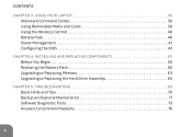
CONTENTS CHAPTER 3: USING YOUR LAPTOP 35 Alienware Command Center 36 Using Removable Media and Cards 39 Using the Wireless Control 40 Battery Pack 40 Power Management 41 Configuring the BIOS 43 CHAPTER 4: INSTALLING AND REPLACING COMPONENTS 55 Before You Begin 56 Replacing the Battery Pack 60 Upgrading or Replacing Memory 63 Upgrading or Replacing the Hard Drive Assembly 65 CHAPTER 5: TROUBLESHOOTING 69 Basic Hints and Tips 70 Backup and General Maintenance 71 Software Diagnostic Tools 73 Answers to Common Problems 76 4
CONTENTS CHAPTER 3: USING YOUR LAPTOP 35 Alienware Command Center 36 Using Removable Media and Cards 39 Using the Wireless Control 40 Battery Pack 40 Power Management 41 Configuring the BIOS 43 CHAPTER 4: INSTALLING AND REPLACING COMPONENTS 55 Before You Begin 56 Replacing the Battery Pack 60 Upgrading or Replacing Memory 63 Upgrading or Replacing the Hard Drive Assembly 65 CHAPTER 5: TROUBLESHOOTING 69 Basic Hints and Tips 70 Backup and General Maintenance 71 Software Diagnostic Tools 73 Answers to Common Problems 76 4
Mobile Manual
Page 36
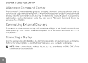
... the connectors on your computer and display. Connecting a Display Use the appropriate cable based on the connectors available on your desktop area, you can access Alienware Command Center by pressing . You can connect an external display such as a standalone monitor, an LCD TV, or a projector. Connecting External Displays If you to Alienware's exclusive software and is a continuously upgradable control panel. NOTE: When connecting to a single display, connect the display to identify the connectors on...
... the connectors on your computer and display. Connecting a Display Use the appropriate cable based on the connectors available on your desktop area, you can access Alienware Command Center by pressing . You can connect an external display such as a standalone monitor, an LCD TV, or a projector. Connecting External Displays If you to Alienware's exclusive software and is a continuously upgradable control panel. NOTE: When connecting to a single display, connect the display to identify the connectors on...
Mobile Manual
Page 39
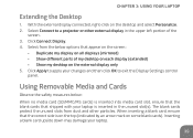
... no media card (SD/MMC/MS cards) is inserted into media card slot, ensure that the blank cards that shipped with your laptop is on the top (indicated by an arrow mark on the external display only 5. Inserting a blank card upside down may damage your changes and then click OK to apply your laptop. 39 Click Connect Display. 4. Using Removable Media and Cards Observe the safety measures below options that the...
... no media card (SD/MMC/MS cards) is inserted into media card slot, ensure that the blank cards that shipped with your laptop is on the top (indicated by an arrow mark on the external display only 5. Inserting a blank card upside down may damage your changes and then click OK to apply your laptop. 39 Click Connect Display. 4. Using Removable Media and Cards Observe the safety measures below options that the...

Mobile Manual
Page 53
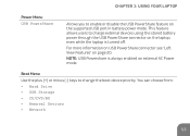
Boot Menu Use the plus (+) or minus (-) keys to change the boot device priority. You can choose from: • Hard Drive • USB Storage • CD/DVD/BD • Removal Devices • Network 53 For more information on USB PowerShare connector see "Left View Features" on the laptop, even while the laptop is always enabled on the supported USB port in battery power mode. This feature allows users to charge external devices using the stored battery power through the USB PowerShare connector on...
Boot Menu Use the plus (+) or minus (-) keys to change the boot device priority. You can choose from: • Hard Drive • USB Storage • CD/DVD/BD • Removal Devices • Network 53 For more information on USB PowerShare connector see "Left View Features" on the laptop, even while the laptop is always enabled on the supported USB port in battery power mode. This feature allows users to charge external devices using the stored battery power through the USB PowerShare connector on...
Mobile Manual
Page 65
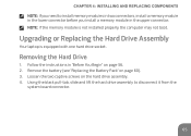
... lower connector before you install a memory module in "Before You Begin" on page 56. 2. Loosen the two captive screws on page 60). 3. Follow the instructions in the upper connector. CHAPTER 4: INSTALLING AND REPLACING COMPONENTS NOTE: If you need to disconnect it from the system board connector. 65 Upgrading or Replacing the Hard Drive Assembly Your laptop is not installed properly, the computer may not boot.
... lower connector before you install a memory module in "Before You Begin" on page 56. 2. Loosen the two captive screws on page 60). 3. Follow the instructions in the upper connector. CHAPTER 4: INSTALLING AND REPLACING COMPONENTS NOTE: If you need to disconnect it from the system board connector. 65 Upgrading or Replacing the Hard Drive Assembly Your laptop is not installed properly, the computer may not boot.
MOBILE MANUAL
Page 4
CONTENTS CHAPTER 3: USING YOUR LAPTOP 35 Alienware Command Center 36 Using Removable Media and Cards 39 Using the Wireless Control 40 Battery Pack 40 Power Management 41 Configuring the BIOS 43 CHAPTER 4: INSTALLING AND REPLACING COMPONENTS 55 Before You Begin 56 Replacing the Battery Pack 60 Upgrading or Replacing Memory 63 Upgrading or Replacing the Hard Drive Assembly 65 CHAPTER 5: TROUBLESHOOTING 69 Basic Hints and Tips 70 Backup and General Maintenance 71 Software Diagnostic Tools 73 Answers to Common Problems 76 4
CONTENTS CHAPTER 3: USING YOUR LAPTOP 35 Alienware Command Center 36 Using Removable Media and Cards 39 Using the Wireless Control 40 Battery Pack 40 Power Management 41 Configuring the BIOS 43 CHAPTER 4: INSTALLING AND REPLACING COMPONENTS 55 Before You Begin 56 Replacing the Battery Pack 60 Upgrading or Replacing Memory 63 Upgrading or Replacing the Hard Drive Assembly 65 CHAPTER 5: TROUBLESHOOTING 69 Basic Hints and Tips 70 Backup and General Maintenance 71 Software Diagnostic Tools 73 Answers to Common Problems 76 4

MOBILE MANUAL
Page 36
... desktop area, you to ONLY ONE of system management, optimization, and customization tools. You can connect an external display such as a standalone monitor, an LCD TV, or a projector. Refer to the following table to Alienware's exclusive software and is a continuously upgradable control panel. CHAPTER 3: USING YOUR LAPTOP Alienware Command Center The Alienware® Command Center gives you access to identify the connectors on a bigger scale visually...
... desktop area, you to ONLY ONE of system management, optimization, and customization tools. You can connect an external display such as a standalone monitor, an LCD TV, or a projector. Refer to the following table to Alienware's exclusive software and is a continuously upgradable control panel. CHAPTER 3: USING YOUR LAPTOP Alienware Command Center The Alienware® Command Center gives you access to identify the connectors on a bigger scale visually...
MOBILE MANUAL
Page 53
... enable or disable the USB PowerShare feature on the laptop, even while the laptop is always enabled on page 20. You can choose from: • Hard Drive • USB Storage • CD/DVD/BD • Removal Devices • Network 53 This feature allows users to change the boot device priority. Boot Menu Use the plus (+) or minus (-) keys to charge external devices using the stored battery power through the USB PowerShare connector on the supported USB port in battery power mode. NOTE: USB Powershare is turned...
... enable or disable the USB PowerShare feature on the laptop, even while the laptop is always enabled on page 20. You can choose from: • Hard Drive • USB Storage • CD/DVD/BD • Removal Devices • Network 53 This feature allows users to change the boot device priority. Boot Menu Use the plus (+) or minus (-) keys to charge external devices using the stored battery power through the USB PowerShare connector on the supported USB port in battery power mode. NOTE: USB Powershare is turned...
Service Manual
Page 1
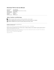
... manner whatsoever without notice. © 2010 Dell Inc. Bluetooth is used by Bluetooth SIG, Inc. Dell Inc. Regulatory model P06T series Regulatory type P06T001/P06T002 February 2010 Rev. Alienware® M11x Service Manual Before You Begin Base Cover Battery Pack Hard-Drive Assembly Memory Module(s) Wireless Mini-Card(s) Hinge Cover Keyboard Palm Rest Assembly Status Light Board Power Button Board Internal Card With Bluetooth® Wireless Technology Coin-Cell Battery Display Assembly I/O Board System Board Speakers Flashing the BIOS Notes, Cautions, and Warnings NOTE: A NOTE...
... manner whatsoever without notice. © 2010 Dell Inc. Bluetooth is used by Bluetooth SIG, Inc. Dell Inc. Regulatory model P06T series Regulatory type P06T001/P06T002 February 2010 Rev. Alienware® M11x Service Manual Before You Begin Base Cover Battery Pack Hard-Drive Assembly Memory Module(s) Wireless Mini-Card(s) Hinge Cover Keyboard Palm Rest Assembly Status Light Board Power Button Board Internal Card With Bluetooth® Wireless Technology Coin-Cell Battery Display Assembly I/O Board System Board Speakers Flashing the BIOS Notes, Cautions, and Warnings NOTE: A NOTE...
Service Manual
Page 7
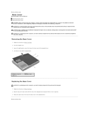
... Before You Begin. 2. Follow the instructions in Before You Begin. 2. Back to the computer, use batteries designed for this particular Dell computer. Back to Contents Page Base Cover Alienware® M11x Service Manual Removing the Base Cover Replacing the Base Cover WARNING: Before working inside your computer, read the safety information that secure the base cover to the computer base. 4. Turn the computer over. 3. CAUTION: To...
... Before You Begin. 2. Follow the instructions in Before You Begin. 2. Back to the computer, use batteries designed for this particular Dell computer. Back to Contents Page Base Cover Alienware® M11x Service Manual Removing the Base Cover Replacing the Base Cover WARNING: Before working inside your computer, read the safety information that secure the base cover to the computer base. 4. Turn the computer over. 3. CAUTION: To...
Service Manual
Page 15
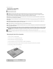
... Cover). 3. Do not remove the hard drive while the computer is hot, do not touch the metal housing of the computer base. 1 captive screws (2) 3 hard-drive assembly 2 pull-tab WARNING: Before working inside your computer (see Turning Off Your Computer) before working inside the computer. As you remove the hard drive from the connector on the new hard drive. Back to Contents Page Hard-Drive Assembly Alienware® M11x Service Manual Removing the Hard-Drive Assembly Replacing...
... Cover). 3. Do not remove the hard drive while the computer is hot, do not touch the metal housing of the computer base. 1 captive screws (2) 3 hard-drive assembly 2 pull-tab WARNING: Before working inside your computer (see Turning Off Your Computer) before working inside the computer. As you remove the hard drive from the connector on the new hard drive. Back to Contents Page Hard-Drive Assembly Alienware® M11x Service Manual Removing the Hard-Drive Assembly Replacing...

Service Manual
Page 16
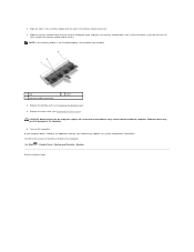
... 7. Install the drivers and utilities for your computer, as needed . 11. Place the hard-drive assembly in the computer, store it to the hard-drive bracket. 8. Replace the battery pack (see Replacing the Base Cover). Replace the base cover (see Replacing the Battery Pack). 9. Install the operating system for storing or shipping the hard drive. 3. Tighten the two captive screws that shipped with your computer). CAUTION: Before turning on the computer, replace...
... 7. Install the drivers and utilities for your computer, as needed . 11. Place the hard-drive assembly in the computer, store it to the hard-drive bracket. 8. Replace the battery pack (see Replacing the Base Cover). Replace the base cover (see Replacing the Battery Pack). 9. Install the operating system for storing or shipping the hard drive. 3. Tighten the two captive screws that shipped with your computer). CAUTION: Before turning on the computer, replace...

Service Manual
Page 26
... a connector on the system board. Remove the base cover (see Removing the Battery Pack). CAUTION: To prevent damage to the memory module connector, do not use tools to install memory modules in two connectors, install a memory module in the lower connector before working inside the computer. Follow the instructions in Before You Begin. 2. Back to Contents Page Memory Module(s) Alienware® M11x Service Manual Removing the Memory Module(s) Replacing the Memory Module(s) WARNING: Before working inside your computer, read...
... a connector on the system board. Remove the base cover (see Removing the Battery Pack). CAUTION: To prevent damage to the memory module connector, do not use tools to install memory modules in two connectors, install a memory module in the lower connector before working inside the computer. Follow the instructions in Before You Begin. 2. Back to Contents Page Memory Module(s) Alienware® M11x Service Manual Removing the Memory Module(s) Replacing the Memory Module(s) WARNING: Before working inside your computer, read...
Service Manual
Page 27
... so may not boot. 1 tab 3 memory module connector 2 notch 4. Replace the base cover (see Replacing the Battery Pack). 5. Back to do not hear the click, remove the memory module and reinstall it clicks into the slot at a 45-degree angle, and press the memory module down until it . 2. Align the notch in the memory module with the tab in the computer: Click Start ® Control Panel® System...
... so may not boot. 1 tab 3 memory module connector 2 notch 4. Replace the base cover (see Replacing the Battery Pack). 5. Back to do not hear the click, remove the memory module and reinstall it clicks into the slot at a 45-degree angle, and press the memory module down until it . 2. Align the notch in the memory module with the tab in the computer: Click Start ® Control Panel® System...
Service Manual
Page 29
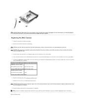
... secures the Mini-Card to the system board. 5. Back to ensure correct insertion. Remove the new Mini-Card from a source other end of the Mini-Card down into the slot on the system board, and realign the card. 3. CAUTION: The connectors are installing a communication card from its packaging. Press the other than Dell or Alienware, you must install the appropriate drivers and utilities. Connect the appropriate antenna...
... secures the Mini-Card to the system board. 5. Back to ensure correct insertion. Remove the new Mini-Card from a source other end of the Mini-Card down into the slot on the system board, and realign the card. 3. CAUTION: The connectors are installing a communication card from its packaging. Press the other than Dell or Alienware, you must install the appropriate drivers and utilities. Connect the appropriate antenna...
Service Manual
Page 36
.... Remove the Bluetooth™ card (see Removing the Palm Rest Assembly). 11. CAUTION: To avoid electrostatic discharge, ground yourself by using a wrist grounding strap or by Dell™ is also visible on a barcode label on the system board. Follow the instructions in -1 Media Card reader slot. 3. Remove the base cover (see Removing the Memory Module(s)). 8. Remove the memory module(s) (see Removing the Base Cover). 4. Remove the I /O Board). 15. CAUTION: Only a certified service technician should perform repairs...
.... Remove the Bluetooth™ card (see Removing the Palm Rest Assembly). 11. CAUTION: To avoid electrostatic discharge, ground yourself by using a wrist grounding strap or by Dell™ is also visible on a barcode label on the system board. Follow the instructions in -1 Media Card reader slot. 3. Remove the base cover (see Removing the Memory Module(s)). 8. Remove the memory module(s) (see Removing the Base Cover). 4. Remove the I /O Board). 15. CAUTION: Only a certified service technician should perform repairs...


