
Mobile Manual
Page 44
... normally enter manually, such as a user ID and password for a Windows account or a secure web site. For example, if four lights turn on your Alienware computer secure by using the unique appearance of the total battery charge. Battery Pack Your laptop is no charge remaining in the battery. 42 For more information, click Start → Programs→ FastAccess. The battery meter lights on the battery pack indicate the charge level of battery charge...
... normally enter manually, such as a user ID and password for a Windows account or a secure web site. For example, if four lights turn on your Alienware computer secure by using the unique appearance of the total battery charge. Battery Pack Your laptop is no charge remaining in the battery. 42 For more information, click Start → Programs→ FastAccess. The battery meter lights on the battery pack indicate the charge level of battery charge...
Mobile Manual
Page 70
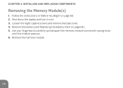
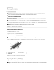
Remove the battery (see "Replacing the Battery Pack" on page 60. 2. Follow the instructions in "Before You Begin" on page 64). 5. Use your fingertips to carefully spread apart the memory module connector's spring-locks until the module pops up. 6. Remove the memory module. 68 CHAPTER 4: INSTALLING AND REPLACING COMPONENTS Removing the Memory Module(s) 1. Loosen the eight captive screws and remove the base cover. 4. Shut down the laptop and turn it over. 3.
Remove the battery (see "Replacing the Battery Pack" on page 60. 2. Follow the instructions in "Before You Begin" on page 64). 5. Use your fingertips to carefully spread apart the memory module connector's spring-locks until the module pops up. 6. Remove the memory module. 68 CHAPTER 4: INSTALLING AND REPLACING COMPONENTS Removing the Memory Module(s) 1. Loosen the eight captive screws and remove the base cover. 4. Shut down the laptop and turn it over. 3.
Service Manual
Page 1
... names may be used by Bluetooth SIG, Inc. Alienware® M11x R3 Service Manual Before You Begin Base Cover Battery Pack Hard Drive Memory Module(s) Wireless Mini-Card(s) Hinge Cover Keyboard Palm Rest Assembly Status Light Board Power Button Board Internal Card With Bluetooth Wireless Technology Coin-Cell Battery Display Assembly I/O Board System Board Speakers System Setup Flashing the BIOS Regulatory model: P06T series Regulatory type: P06T003 Notes, Cautions, and Warnings NOTE: A NOTE indicates important information that helps you make better use of Dell Inc.; Reproduction of...
... names may be used by Bluetooth SIG, Inc. Alienware® M11x R3 Service Manual Before You Begin Base Cover Battery Pack Hard Drive Memory Module(s) Wireless Mini-Card(s) Hinge Cover Keyboard Palm Rest Assembly Status Light Board Power Button Board Internal Card With Bluetooth Wireless Technology Coin-Cell Battery Display Assembly I/O Board System Board Speakers System Setup Flashing the BIOS Regulatory model: P06T series Regulatory type: P06T003 Notes, Cautions, and Warnings NOTE: A NOTE indicates important information that helps you make better use of Dell Inc.; Reproduction of...
Service Manual
Page 6
... BIOS Setup Utility by pressing when prompted. Memory Bank 0 Displays the memory size installed in DIMM 1. Memory Bank 1 Displays the memory size installed in DIMM 0. To avoid possible keyboard failure, press and release in System Setup unless you are an expert computer user. l View the installed amount of memory or set the type of your computer. Back to Contents Page System Setup Alienware® M11x R3 Service Manual Configuring the System Setup Configuring the System Setup The System Setup options...
... BIOS Setup Utility by pressing when prompted. Memory Bank 0 Displays the memory size installed in DIMM 1. Memory Bank 1 Displays the memory size installed in DIMM 0. To avoid possible keyboard failure, press and release in System Setup unless you are an expert computer user. l View the installed amount of memory or set the type of your computer. Back to Contents Page System Setup Alienware® M11x R3 Service Manual Configuring the System Setup Configuring the System Setup The System Setup options...
Service Manual
Page 7
... memory key) when this feature may not wake the computer. l Disabled: BIOS will not detect unsupported AC adapters and will detect unsupported AC adapters and display an error on the screen. l Enabled: BIOS will not display any type of devices plugged into the USB Powershare connector while in the absence of the integrated SATA hard drive controller. Charger Behavior Allows you to enable or disable battery charging. Wireless Menu Bluetooth Allows you to enable or disable the internal Bluetooth device. l Disabled...
... memory key) when this feature may not wake the computer. l Disabled: BIOS will not detect unsupported AC adapters and will detect unsupported AC adapters and display an error on the screen. l Enabled: BIOS will not display any type of devices plugged into the USB Powershare connector while in the absence of the integrated SATA hard drive controller. Charger Behavior Allows you to enable or disable battery charging. Wireless Menu Bluetooth Allows you to enable or disable the internal Bluetooth device. l Disabled...
Service Manual
Page 8
... the computer at boot. Boot Menu Use the or keys to CMOS. Save Change Without Allows you remain in System Setup and save your changes to set the service tag of your computer, if a service tag has not already been set the user password. Allows you to enable or disable the Computrace security feature on your changes to change the boot device priority. Allows you to set . Set Service Tag Set Supervisor Password Set User Password Computrace Allows you...
... the computer at boot. Boot Menu Use the or keys to CMOS. Save Change Without Allows you remain in System Setup and save your changes to set the service tag of your computer, if a service tag has not already been set the user password. Allows you to enable or disable the Computrace security feature on your changes to change the boot device priority. Allows you to set . Set Service Tag Set Supervisor Password Set User Password Computrace Allows you...
Service Manual
Page 10
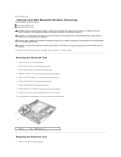
... Removing the Battery Pack). 4. Damage due to servicing that secures the Bluetooth card to the system board. 10. Follow the instructions in Before You Begin Remove the palm rest assembly (see Removing the Battery Pack) before working inside the computer. Remove the screw that is not authorized by Dell™ is already installed. Back to Contents Page Internal Card With Bluetooth Wireless Technology Alienware® M11x R3 Service Manual Removing the Bluetooth Card Replacing the Bluetooth Card WARNING: Before working...
... Removing the Battery Pack). 4. Damage due to servicing that secures the Bluetooth card to the system board. 10. Follow the instructions in Before You Begin Remove the palm rest assembly (see Removing the Battery Pack) before working inside the computer. Remove the screw that is not authorized by Dell™ is already installed. Back to Contents Page Internal Card With Bluetooth Wireless Technology Alienware® M11x R3 Service Manual Removing the Bluetooth Card Replacing the Bluetooth Card WARNING: Before working...
Service Manual
Page 12
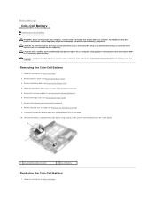
...-Cell Battery Alienware® M11x R3 Service Manual Removing the Coin-Cell Battery Replacing the Coin-Cell Battery WARNING: Before working inside your computer, read the safety information that is not authorized by Dell™ is glued to the system board. CAUTION: To avoid electrostatic discharge, ground yourself by using a wrist grounding strap or by your computer. Follow the instructions from the system board. 1 coin-cell battery cable...
...-Cell Battery Alienware® M11x R3 Service Manual Removing the Coin-Cell Battery Replacing the Coin-Cell Battery WARNING: Before working inside your computer, read the safety information that is not authorized by Dell™ is glued to the system board. CAUTION: To avoid electrostatic discharge, ground yourself by using a wrist grounding strap or by your computer. Follow the instructions from the system board. 1 coin-cell battery cable...
Service Manual
Page 14
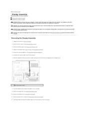
... Contents Page Display Assembly Alienware® M11x R3 Service Manual Removing the Display Assembly Replacing the Display Assembly WARNING: Before working inside your computer, read the safety information that is not authorized by Dell™ is not covered by periodically touching an unpainted metal surface (such as possible. 9. Removing the Display Assembly 1. Remove the battery pack (see Removing the Palm Rest Assembly). 12. Follow the instructions from the routing guides on...
... Contents Page Display Assembly Alienware® M11x R3 Service Manual Removing the Display Assembly Replacing the Display Assembly WARNING: Before working inside your computer, read the safety information that is not authorized by Dell™ is not covered by periodically touching an unpainted metal surface (such as possible. 9. Removing the Display Assembly 1. Remove the battery pack (see Removing the Palm Rest Assembly). 12. Follow the instructions from the routing guides on...
Service Manual
Page 18
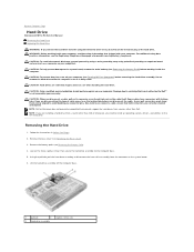
... a cable, pull on its connector or on its pull-tab, not on your computer. Also, before you pull connectors apart, keep them evenly aligned to avoid bending any connector pins. if you are installing a hard drive from a source other than Dell or Alienware, you need to install an operating system, drivers, and utilities on the system board. 6. Back to Contents Page Hard Drive Alienware® M11x R3 Service Manual Removing the Hard Drive Replacing...
... a cable, pull on its connector or on its pull-tab, not on your computer. Also, before you pull connectors apart, keep them evenly aligned to avoid bending any connector pins. if you are installing a hard drive from a source other than Dell or Alienware, you need to install an operating system, drivers, and utilities on the system board. 6. Back to Contents Page Hard Drive Alienware® M11x R3 Service Manual Removing the Hard Drive Replacing...
Service Manual
Page 19
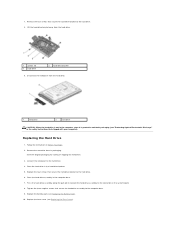
... hard drive. 3. Replace the battery pack (see Replacing the Base Cover). Place the hard-drive assembly in the hard-drive bracket. 5. Remove the new drive from the hard drive. 1 screws (4) 3 hard drive 2 hard-drive bracket 9. Place the hard drive in the computer base. 7. Replace the four screws that secure the hard-drive assembly to the hard drive. 6. Replace the base cover (see Replacing the Battery Pack). 10. Replacing the Hard Drive 1. Lift the hard-drive bracket away from its packaging. Follow the instructions in the safety instructions...
... hard drive. 3. Replace the battery pack (see Replacing the Base Cover). Place the hard-drive assembly in the hard-drive bracket. 5. Remove the new drive from the hard drive. 1 screws (4) 3 hard drive 2 hard-drive bracket 9. Place the hard drive in the computer base. 7. Replace the four screws that secure the hard-drive assembly to the hard drive. 6. Replace the base cover (see Replacing the Battery Pack). 10. Replacing the Hard Drive 1. Lift the hard-drive bracket away from its packaging. Follow the instructions in the safety instructions...
Service Manual
Page 21
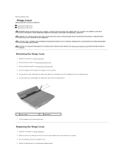
... display and turn the computer over and open the display as far as a connector on your computer. Back to Contents Page Hinge Cover Alienware® M11x R3 Service Manual Removing the Hinge Cover Replacing the Hinge Cover WARNING: Before working inside your computer). Removing the Hinge Cover 1. Turn the computer over . 4. Follow the instructions in Before You Begin. 2. Remove the base cover (see Removing the Battery Pack). 4. CAUTION: Only a certified service technician should perform repairs...
... display and turn the computer over and open the display as far as a connector on your computer. Back to Contents Page Hinge Cover Alienware® M11x R3 Service Manual Removing the Hinge Cover Replacing the Hinge Cover WARNING: Before working inside your computer). Removing the Hinge Cover 1. Turn the computer over . 4. Follow the instructions in Before You Begin. 2. Remove the base cover (see Removing the Battery Pack). 4. CAUTION: Only a certified service technician should perform repairs...
Service Manual
Page 23
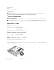
... I/O board out of the slots on the I/O board. 10. Using the pull-tab, gently pull the I/O board to the computer base. 11. Remove the hinge cover (see Removing the Keyboard). 8. Disconnect the speaker cable from step 4 to the system board, remove the main battery (see the Regulatory Compliance Homepage at www.dell.com/regulatory_compliance. Back to Contents Page I/O Board Alienware® M11x R3 Service Manual Removing the I/O Board Replacing the I/O Board WARNING: Before working inside...
... I/O board out of the slots on the I/O board. 10. Using the pull-tab, gently pull the I/O board to the computer base. 11. Remove the hinge cover (see Removing the Keyboard). 8. Disconnect the speaker cable from step 4 to the system board, remove the main battery (see the Regulatory Compliance Homepage at www.dell.com/regulatory_compliance. Back to Contents Page I/O Board Alienware® M11x R3 Service Manual Removing the I/O Board Replacing the I/O Board WARNING: Before working inside...
Service Manual
Page 25
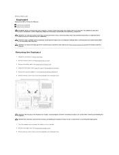
... Before You Begin. 2. CAUTION: Only a certified service technician should perform repairs on the keyboard are fragile, easily dislodged, and time-consuming to step 6 in Removing the Hard Drive. 5. CAUTION: The keycaps on your computer. Be careful when removing and handling the keyboard. Back to Contents Page Keyboard Alienware® M11x R3 Service Manual Removing the Keyboard Replacing the Keyboard WARNING: Before working inside your computer, read the safety information...
... Before You Begin. 2. CAUTION: Only a certified service technician should perform repairs on the keyboard are fragile, easily dislodged, and time-consuming to step 6 in Removing the Hard Drive. 5. CAUTION: The keycaps on your computer. Be careful when removing and handling the keyboard. Back to Contents Page Keyboard Alienware® M11x R3 Service Manual Removing the Keyboard Replacing the Keyboard WARNING: Before working inside your computer, read the safety information...
Service Manual
Page 28
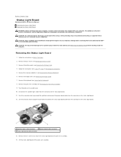
... practices information, see Removing the Memory Module(s)). 6. Follow the instructions from the connector on the status light board. 12. Push the connector latch up and pull the pull-tab to disconnect the power board cable from step 4 to step 6 in Before You Begin. 2. Back to Contents Page Status Light Board Alienware® M11x R3 Service Manual Removing the Status Light Board Replacing the Status Light Board WARNING: Before working inside your computer, read...
... practices information, see Removing the Memory Module(s)). 6. Follow the instructions from the connector on the status light board. 12. Push the connector latch up and pull the pull-tab to disconnect the power board cable from step 4 to step 6 in Before You Begin. 2. Back to Contents Page Status Light Board Alienware® M11x R3 Service Manual Removing the Status Light Board Replacing the Status Light Board WARNING: Before working inside your computer, read...
Service Manual
Page 30
... carefully spread apart the securing clips on your computer. Follow the instructions in Before You Begin. For additional safety best practices information, see Removing the Battery Pack) before you need to install memory modules in two connectors, install a memory module in the upper connector. Your computer has two user-accessible SODIMM connectors. Back to Contents Page Memory Module(s) Alienware® M11x R3 Service Manual Removing the Memory Module(s) Replacing the Memory Module(s) WARNING: Before working inside your...
... carefully spread apart the securing clips on your computer. Follow the instructions in Before You Begin. For additional safety best practices information, see Removing the Battery Pack) before you need to install memory modules in two connectors, install a memory module in the upper connector. Your computer has two user-accessible SODIMM connectors. Back to Contents Page Memory Module(s) Alienware® M11x R3 Service Manual Removing the Memory Module(s) Replacing the Memory Module(s) WARNING: Before working inside your...

Service Manual
Page 33
... stripe Auxiliary WWAN (black triangle) black with your computer. Failure to ensure correct insertion. Replacing the Mini-Card(s) 1. Follow the instructions in damage to Contents Page Connectors on the system board and replace the screw that no stray screws remain inside the computer. Replace the battery pack (see Replacing the Base Cover). Install the drivers and utilities for each MiniCard supported by your computer, as...
... stripe Auxiliary WWAN (black triangle) black with your computer. Failure to ensure correct insertion. Replacing the Mini-Card(s) 1. Follow the instructions in damage to Contents Page Connectors on the system board and replace the screw that no stray screws remain inside the computer. Replace the battery pack (see Replacing the Base Cover). Install the drivers and utilities for each MiniCard supported by your computer, as...
Service Manual
Page 34
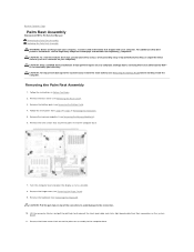
... You Begin. 2. Remove the keyboard (see the Regulatory Compliance Homepage at www.dell.com/regulatory_compliance. Back to Contents Page Palm Rest Assembly Alienware® M11x R3 Service Manual Removing the Palm Rest Assembly Replacing the Palm Rest Assembly WARNING: Before working inside your computer. CAUTION: To help prevent damage to the system board, remove the main battery (see Removing the Battery Pack) before working inside the computer.
... You Begin. 2. Remove the keyboard (see the Regulatory Compliance Homepage at www.dell.com/regulatory_compliance. Back to Contents Page Palm Rest Assembly Alienware® M11x R3 Service Manual Removing the Palm Rest Assembly Replacing the Palm Rest Assembly WARNING: Before working inside your computer. CAUTION: To help prevent damage to the system board, remove the main battery (see Removing the Battery Pack) before working inside the computer.
Service Manual
Page 37
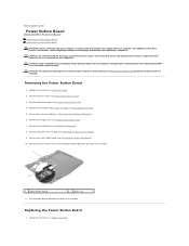
... (see Removing the Battery Pack). 4. Back to Contents Page Power Button Board Alienware® M11x R3 Service Manual Removing the Power Button Board Replacing the Power Button Board WARNING: Before working inside your computer, read the safety information that is not authorized by Dell™ is not covered by periodically touching an unpainted metal surface (such as a connector on your computer. Follow the instructions in Before You Begin. Remove the battery pack (see Removing the Palm...
... (see Removing the Battery Pack). 4. Back to Contents Page Power Button Board Alienware® M11x R3 Service Manual Removing the Power Button Board Replacing the Power Button Board WARNING: Before working inside your computer, read the safety information that is not authorized by Dell™ is not covered by periodically touching an unpainted metal surface (such as a connector on your computer. Follow the instructions in Before You Begin. Remove the battery pack (see Removing the Palm...
Service Manual
Page 40
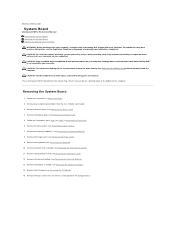
... System Board Alienware® M11x R3 Service Manual Removing the System Board Replacing the System Board Entering the Service Tag in the BIOS WARNING: Before working inside your computer, read the safety information that shipped with your warranty. Removing the System Board 1. Remove the Mini-Card(s) (see Removing the Display Assembly). 14. Remove the memory module(s) (see Removing the Coin-Cell Battery). 13. Remove the coin-cell battery (see Removing the Memory Module(s)). 8. Follow the instructions from the 3-in-1 Media Card reader. 3. Remove the Bluetooth® card...
... System Board Alienware® M11x R3 Service Manual Removing the System Board Replacing the System Board Entering the Service Tag in the BIOS WARNING: Before working inside your computer, read the safety information that shipped with your warranty. Removing the System Board 1. Remove the Mini-Card(s) (see Removing the Display Assembly). 14. Remove the memory module(s) (see Removing the Coin-Cell Battery). 13. Remove the coin-cell battery (see Removing the Memory Module(s)). 8. Follow the instructions from the 3-in-1 Media Card reader. 3. Remove the Bluetooth® card...


