
Tobii Eye Tracker Users Guide
Page 6
... on the touch pad to zoom where you are not in front of it . Default: OFF. Default: ON. Default: ON. Lights up the keyboard keys when you look . Default: ON. Press the button of your choice to trigger the pointer to determine the region you are looking. Default: ...Zoom at gaze Mouse Warp on mouse move Warp on mouse button Windows Application switcher Look at the Alienware logo. Default: ON. 6 Turns off screen Go to scroll. Turns off lights Light up keyboard Reduces screen brightness when you look . Release the Alt key to open the highlighted application. Look at...
... on the touch pad to zoom where you are not in front of it . Default: OFF. Default: ON. Default: ON. Lights up the keyboard keys when you look . Default: ON. Press the button of your choice to trigger the pointer to determine the region you are looking. Default: ...Zoom at gaze Mouse Warp on mouse move Warp on mouse button Windows Application switcher Look at the Alienware logo. Default: ON. 6 Turns off screen Go to scroll. Turns off lights Light up keyboard Reduces screen brightness when you look . Release the Alt key to open the highlighted application. Look at...
Tobii Eye Tracker Users Guide
Page 7
... the Enter key to www.dell.com/support. 3. Detailed information about Tobii eye-tracker on using the Tobii eye-tracker. Go to open the application. Click Product support, enter the Service Tag of your field of vision with a bubble. Scroll down the page and expand Mouse, Keyboard & Input Devices. 6. Default: ON. Reset...
... the Enter key to www.dell.com/support. 3. Detailed information about Tobii eye-tracker on using the Tobii eye-tracker. Go to open the application. Click Product support, enter the Service Tag of your field of vision with a bubble. Scroll down the page and expand Mouse, Keyboard & Input Devices. 6. Default: ON. Reset...
Service Manual
Page 6
... Removing the touchpad...53 Prerequisites...53 Procedure...53 38 Replacing the touchpad...54 Procedure...54 Post-requisites...55 39 Removing the keyboard...56 Prerequisites...56 Procedure...56 40 Replacing the keyboard...58 Procedure...58 Post-requisites...59 41 Removing the palm rest...60 Prerequisites...60 Procedure...60 42 Replacing the palm rest...
... Removing the touchpad...53 Prerequisites...53 Procedure...53 38 Replacing the touchpad...54 Procedure...54 Post-requisites...55 39 Removing the keyboard...56 Prerequisites...56 Procedure...56 40 Replacing the keyboard...58 Procedure...58 Post-requisites...59 41 Removing the palm rest...60 Prerequisites...60 Procedure...60 42 Replacing the palm rest...
Service Manual
Page 9
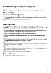
... surface to avoid bending any connector pins. Some cables have connectors with the product or at www.dell.com/regulatory_compliance. When disconnecting cables, keep them by their electrical outlets. 4. Recommended tools The procedures...see the documentation of the computer. CAUTION: To avoid damaging the computer, ensure that is not authorized by Dell is flat and clean. Safety instructions Use the following tools: • Phillips screwdriver #1 • Plastic scribe... by touching an unpainted metal surface, such as keyboard, mouse, and monitor from your computer. 5.
... surface to avoid bending any connector pins. Some cables have connectors with the product or at www.dell.com/regulatory_compliance. When disconnecting cables, keep them by their electrical outlets. 4. Recommended tools The procedures...see the documentation of the computer. CAUTION: To avoid damaging the computer, ensure that is not authorized by Dell is flat and clean. Safety instructions Use the following tools: • Phillips screwdriver #1 • Plastic scribe... by touching an unpainted metal surface, such as keyboard, mouse, and monitor from your computer. 5.
Service Manual
Page 10
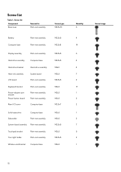
... Screw type M2.5x13 Battery Computer base Palm-rest assembly Palm-rest assembly Display assembly Hard-drive assembly Hard-drive bracket Heat-sink assembly I/O board Keyboard bracket Power-adapter port bracket Power-button board Rear-I/O cover Palm-rest assembly Computer base Hard-drive assembly System board Palm-rest assembly Palm-rest... M2.5x8 M2.5x5 M2.5x5 M3x3 M2x3 M2.5x5 M2x3 M2x3 M2x3 M2.5x7 M2x3 M2x2 M2.5x5 M2x3 M2.5x5 M2x3 Quantity 6 4 14 6 4 4 7 2 17 1 2 2 1 2 7 5 2 1 Screw image 10 Screw list Table 1.
... Screw type M2.5x13 Battery Computer base Palm-rest assembly Palm-rest assembly Display assembly Hard-drive assembly Hard-drive bracket Heat-sink assembly I/O board Keyboard bracket Power-adapter port bracket Power-button board Rear-I/O cover Palm-rest assembly Computer base Hard-drive assembly System board Palm-rest assembly Palm-rest... M2.5x8 M2.5x5 M2.5x5 M3x3 M2x3 M2.5x5 M2x3 M2x3 M2x3 M2.5x7 M2x3 M2x2 M2.5x5 M2x3 M2.5x5 M2x3 Quantity 6 4 14 6 4 4 7 2 17 1 2 2 1 2 7 5 2 1 Screw image 10 Screw list Table 1.
Service Manual
Page 39
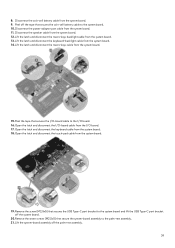
... off the palm-rest assembly. 39 Open the latch and disconnect the I/O-board cable from the system board. 18. Open the latch and disconnect the keyboard cable from the I /O board. 16. Open the latch and disconnect the touch-pad cable from the system board. 15. Lift the latch and ... off the system board. 20.Remove the seven screws (M2.5x5) that secures the coin-cell battery cable to the I /O board. 17. Lift the latch and disconnect the keyboard-backlight cable from the system board. 12. Disconnect the speaker cable from the system board. 14. Peel the tape that secures the...
... off the palm-rest assembly. 39 Open the latch and disconnect the I/O-board cable from the system board. 18. Open the latch and disconnect the keyboard cable from the I /O board. 16. Open the latch and disconnect the touch-pad cable from the system board. 15. Lift the latch and ... off the system board. 20.Remove the seven screws (M2.5x5) that secures the coin-cell battery cable to the I /O board. 17. Lift the latch and disconnect the keyboard-backlight cable from the system board. 12. Disconnect the speaker cable from the system board. 14. Peel the tape that secures the...
Service Manual
Page 41
... Service Tag is stored in Before working inside your computer. For more safety best practices, see the Regulatory Compliance home page at www.dell.com/ regulatory_compliance. Align the screw holes on the system board with the screw hole on the system board. 5. Connect the logo-board...14. Slide the touch-pad cable into their connectors and press down the latches to secure the cable. 12. Insert the keyboard cable, macro-keys backlight cable, and keyboard-backlight cable into the connector on the palm-rest assembly. 3. Post-requisites 1. Replace the computer base. 3. Replace the ...
... Service Tag is stored in Before working inside your computer. For more safety best practices, see the Regulatory Compliance home page at www.dell.com/ regulatory_compliance. Align the screw holes on the system board with the screw hole on the system board. 5. Connect the logo-board...14. Slide the touch-pad cable into their connectors and press down the latches to secure the cable. 12. Insert the keyboard cable, macro-keys backlight cable, and keyboard-backlight cable into the connector on the palm-rest assembly. 3. Post-requisites 1. Replace the computer base. 3. Replace the ...
Service Manual
Page 56
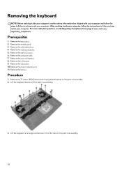
.... Remove the base cover. 2. Remove the coin-cell battery. 8. Lift the keyboard at www.dell.com/ regulatory_compliance. Remove the battery. Remove the computer base. 7. Remove the I /O cover. 6. Lift the keyboard bracket off the palm-rest assembly. 3. Remove the memory modules. 5. Remove the 17 screws (M2x3) that shipped with your computer and follow the instructions...
.... Remove the base cover. 2. Remove the coin-cell battery. 8. Lift the keyboard at www.dell.com/ regulatory_compliance. Remove the battery. Remove the computer base. 7. Remove the I /O cover. 6. Lift the keyboard bracket off the palm-rest assembly. 3. Remove the memory modules. 5. Remove the 17 screws (M2x3) that shipped with your computer and follow the instructions...
Service Manual
Page 58
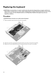
... your computer, read the safety information that there are no cables under the tabs on the palm-rest assembly. 2. Slide the keyboard under the keyboard. 1. After working inside your computer, follow the steps in After working inside your computer. For more safety best practices, see the... Regulatory Compliance home page at www.dell.com/ regulatory_compliance. Replace the 15 screws (M2x3) that secure the keyboard bracket to the palm-rest assembly. 58 Align the screw holes on the keyboard bracket with your computer and follow the instructions in Before working...
... your computer, read the safety information that there are no cables under the tabs on the palm-rest assembly. 2. Slide the keyboard under the keyboard. 1. After working inside your computer, follow the steps in After working inside your computer. For more safety best practices, see the... Regulatory Compliance home page at www.dell.com/ regulatory_compliance. Replace the 15 screws (M2x3) that secure the keyboard bracket to the palm-rest assembly. 58 Align the screw holes on the keyboard bracket with your computer and follow the instructions in Before working...
Service Manual
Page 60
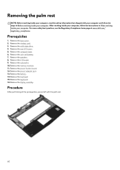
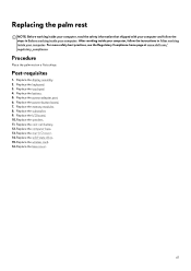
.... Remove the rear-I /O board. 9. Remove the subwoofer. 10. For more safety best practices, see the Regulatory Compliance home page at www.dell.com/ regulatory_compliance. Remove the computer base. 6. Remove the keyboard. 16. Procedure After performing all the prerequisites, we are left with your computer and follow the instructions in Before working inside...
.... Remove the rear-I /O board. 9. Remove the subwoofer. 10. For more safety best practices, see the Regulatory Compliance home page at www.dell.com/ regulatory_compliance. Remove the computer base. 6. Remove the keyboard. 16. Procedure After performing all the prerequisites, we are left with your computer and follow the instructions in Before working inside...
Service Manual
Page 61
Procedure Place the palm rest on a flat surface. Replace the touchpad. 4. Replace the keyboard. 3. Replace the power-adapter port. 6. Replace the wireless card. 16. Replace the I /O cover. 14. Replace the computer base. 13. Replace the rear-I /O board. 10. Replace ... your computer and follow the instructions in Before working inside your computer. For more safety best practices, see the Regulatory Compliance home page at www.dell.com/ regulatory_compliance.
Procedure Place the palm rest on a flat surface. Replace the touchpad. 4. Replace the keyboard. 3. Replace the power-adapter port. 6. Replace the wireless card. 16. Replace the I /O cover. 14. Replace the computer base. 13. Replace the rear-I /O board. 10. Replace ... your computer and follow the instructions in Before working inside your computer. For more safety best practices, see the Regulatory Compliance home page at www.dell.com/ regulatory_compliance.
Service Manual
Page 81
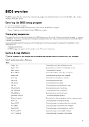
.... Displays the type of third hard-drive installed. Turn on your computer with the Ctrl +Alt+Del key combination. Timing key sequences The keyboard is displayed on the screen to enter the BIOS setup program. As a result, if you cannot restart your computer and its installed devices,... Options NOTE: Depending on or restart your computer. Displays the BIOS version. Displays the processor L1 cache size. Press F2 when the Dell logo is not the first device initialized by the BIOS setup program. Displays the type of secondary hard-drive installed. Displays the model number...
.... Displays the type of third hard-drive installed. Turn on your computer with the Ctrl +Alt+Del key combination. Timing key sequences The keyboard is displayed on the screen to enter the BIOS setup program. As a result, if you cannot restart your computer and its installed devices,... Options NOTE: Depending on or restart your computer. Displays the BIOS version. Displays the processor L1 cache size. Press F2 when the Dell logo is not the first device initialized by the BIOS setup program. Displays the type of secondary hard-drive installed. Displays the model number...
Setup and Specifications
Page 3
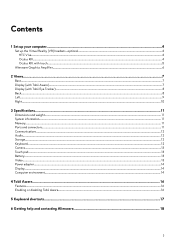
... Set up your computer...4 Set up the Virtual Reality (VR) headset-optional...4 HTC Vive...4 Oculus Rift...4 Oculus Rift with touch...5 Alienware Graphics Amplifier...6 2 Views...7 Base...7 Display (with Tobii Aware)...7 Display (with Tobii Eye Tracker)...8 Back...8 Left...9 Right...10 3 Specifications......11 Dimensions and weight...11 System information...11 Memory...11 Ports and connectors...11 Communications...12 Audio...12 Storage...12 Keyboard...12 Camera...13 Touch pad...13 Battery...13 Video...13 Power adapter...14 Display...14 Computer environment...14 4 Tobii Aware...16 ...
... Set up your computer...4 Set up the Virtual Reality (VR) headset-optional...4 HTC Vive...4 Oculus Rift...4 Oculus Rift with touch...5 Alienware Graphics Amplifier...6 2 Views...7 Base...7 Display (with Tobii Aware)...7 Display (with Tobii Eye Tracker)...8 Back...8 Left...9 Right...10 3 Specifications......11 Dimensions and weight...11 System information...11 Memory...11 Ports and connectors...11 Communications...12 Audio...12 Storage...12 Keyboard...12 Camera...13 Touch pad...13 Battery...13 Video...13 Power adapter...14 Display...14 Computer environment...14 4 Tobii Aware...16 ...
Setup and Specifications
Page 12
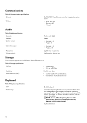
...define the primary behavior of the function keys (F1-F12) by changing Function Key Behavior in BIOS setup program. Keyboard specifications Type Shortcut keys Backlit keyboard Some keys on your keyboard have two symbols on system board • Wi-Fi 802.11ac • Bluetooth 4.1 • Miracast Audio ...Table 5. To perform secondary functions, press Fn and the desired key. Keyboard shortcuts 12 To type the alternate character, press Shift and the desired key. NOTE: You can be used to type alternate characters or to ...
...define the primary behavior of the function keys (F1-F12) by changing Function Key Behavior in BIOS setup program. Keyboard specifications Type Shortcut keys Backlit keyboard Some keys on your keyboard have two symbols on system board • Wi-Fi 802.11ac • Bluetooth 4.1 • Miracast Audio ...Table 5. To perform secondary functions, press Fn and the desired key. Keyboard shortcuts 12 To type the alternate character, press Shift and the desired key. NOTE: You can be used to type alternate characters or to ...
Setup and Specifications
Page 17
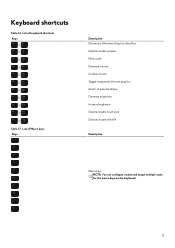
List of Macro keys Keys Description Disconnect Alienware Graphics Amplifier Disable/enable wireless Mute audio Decrease volume Increase volume Toggle integrated/discrete graphics Switch to external display Decrease brightness Increase brightness Disable/enable touch pad Disable/enable AlienFX Description Macro keys NOTE: You can configure modes and assign multiple tasks for the macro keys on the keyboard. 17 List of keyboard shortcuts Keys Table 17. Keyboard shortcuts Table 16.
List of Macro keys Keys Description Disconnect Alienware Graphics Amplifier Disable/enable wireless Mute audio Decrease volume Increase volume Toggle integrated/discrete graphics Switch to external display Decrease brightness Increase brightness Disable/enable touch pad Disable/enable AlienFX Description Macro keys NOTE: You can configure modes and assign multiple tasks for the macro keys on the keyboard. 17 List of keyboard shortcuts Keys Table 17. Keyboard shortcuts Table 16.


