Handling swollen Lithium-ion batteries
Page 1
... newer ultra-thin laptops) and long battery life. Guidelines for options to malfunction, discontinue the use tools of fire or explosion. Contact Dell product support at an approved recycling center. We recommend contacting Dell product support for handling and replacing Lithium-ion batteries ● Exercise caution when handling Lithium-ion batteries. ● Discharge the battery before removing it by a Dell authorized service technician. A05 June...
... newer ultra-thin laptops) and long battery life. Guidelines for options to malfunction, discontinue the use tools of fire or explosion. Contact Dell product support at an approved recycling center. We recommend contacting Dell product support for handling and replacing Lithium-ion batteries ● Exercise caution when handling Lithium-ion batteries. ● Discharge the battery before removing it by a Dell authorized service technician. A05 June...
Tobii Eye Tracker Users Guide
Page 4
... away from the device, and may pose danger or choking hazard, when handled by IR light and/or radiation. If you feel odd sensations before the seizure occurs. These parts may be likely to certain flashing lights or light patterns in everyday life. Safety instructions Use the following safety guidelines for your Tobii Eye Tracker is not working properly. 4
... away from the device, and may pose danger or choking hazard, when handled by IR light and/or radiation. If you feel odd sensations before the seizure occurs. These parts may be likely to certain flashing lights or light patterns in everyday life. Safety instructions Use the following safety guidelines for your Tobii Eye Tracker is not working properly. 4
Tobii Eye Tracker Users Guide
Page 7
... key or the Enter key to the internet. Default: Tick. Go to default. After the download is connected to open the application. Intro Select Intro to highlight it myself. 5. Scroll down the page and expand Mouse, Keyboard & Input Devices. 6. Double-click the Tobii Eye Tracker driver file icon and follow the instructions on this computer. In the Windows Snap assit view, look at an application to start...
... key or the Enter key to the internet. Default: Tick. Go to default. After the download is connected to open the application. Intro Select Intro to highlight it myself. 5. Scroll down the page and expand Mouse, Keyboard & Input Devices. 6. Double-click the Tobii Eye Tracker driver file icon and follow the instructions on this computer. In the Windows Snap assit view, look at an application to start...

Service Manual
Page 3
... begin ...9 Safety instructions...9 Recommended tools...9 Screw list...10 2 After working inside your computer 11 3 Removing the base cover...12 Procedure...12 4 Replacing the base cover...14 Procedure...14 5 Removing the hard drive...15 Prerequisites...15 Procedure...15 6 Replacing the hard drive...17 Procedure...17 Post-requisites...17 7 Removing the wireless card...18 Prerequisites...18 Procedure...18 8 Replacing the wireless card...19 Procedure...19 Post-requisites...19 9 Removing the solid-state drive...20 Prerequisites...20...
... begin ...9 Safety instructions...9 Recommended tools...9 Screw list...10 2 After working inside your computer 11 3 Removing the base cover...12 Procedure...12 4 Replacing the base cover...14 Procedure...14 5 Removing the hard drive...15 Prerequisites...15 Procedure...15 6 Replacing the hard drive...17 Procedure...17 Post-requisites...17 7 Removing the wireless card...18 Prerequisites...18 Procedure...18 8 Replacing the wireless card...19 Procedure...19 Post-requisites...19 9 Removing the solid-state drive...20 Prerequisites...20...
Service Manual
Page 9
... on the configuration you ordered. Disconnect your computer and all covers, panels, and screws before connecting to avoid bending any media card and optical disc from their edges, and avoid touching pins and contacts. CAUTION: You should only perform troubleshooting and repairs as keyboard, mouse, and monitor from your computer depending on the cable itself. Save and close all open applications. 2. NOTE: Before working inside your computer...
... on the configuration you ordered. Disconnect your computer and all covers, panels, and screws before connecting to avoid bending any media card and optical disc from their edges, and avoid touching pins and contacts. CAUTION: You should only perform troubleshooting and repairs as keyboard, mouse, and monitor from your computer depending on the cable itself. Save and close all open applications. 2. NOTE: Before working inside your computer...

Service Manual
Page 23
... the slot at www.dell.com/ regulatory_compliance. For more safety best practices, see the Regulatory Compliance home page at an angle. 2. Post-requisites Replace the base cover. 23 Replacing the memory modules NOTE: Before working inside your computer, read the safety information that shipped with the tab on the memory module with your computer and follow the instructions in Before working inside...
... the slot at www.dell.com/ regulatory_compliance. For more safety best practices, see the Regulatory Compliance home page at an angle. 2. Post-requisites Replace the base cover. 23 Replacing the memory modules NOTE: Before working inside your computer, read the safety information that shipped with the tab on the memory module with your computer and follow the instructions in Before working inside...

Service Manual
Page 29
... battery cable from the system board. 2. For more safety best practices, see the Regulatory Compliance home page at www.dell.com/ regulatory_compliance. Gently peel off the coin-cell battery along with your computer and follow the instructions in Before working inside your computer. Remove the wireless card. 3. Peel off the tape that you note the BIOS setup program's settings before removing the coin-cell battery...
... battery cable from the system board. 2. For more safety best practices, see the Regulatory Compliance home page at www.dell.com/ regulatory_compliance. Gently peel off the coin-cell battery along with your computer and follow the instructions in Before working inside your computer. Remove the wireless card. 3. Peel off the tape that you note the BIOS setup program's settings before removing the coin-cell battery...
Service Manual
Page 38
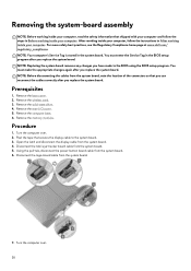
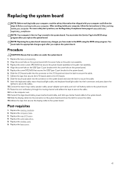
... in After working inside your computer. Remove the memory modules. Turn the computer over . 38 Using the pull-tab, disconnect the power-button board cable from the system board. 7. Disconnect the logo-board cable from the system board. 6. You must enter the Service Tag in the system board. Remove the wireless card. 3. Remove the computer base. 6. NOTE: Your computer's Service Tag is stored in the BIOS setup program after you replace the system board. Peel the...
... in After working inside your computer. Remove the memory modules. Turn the computer over . 38 Using the pull-tab, disconnect the power-button board cable from the system board. 7. Disconnect the logo-board cable from the system board. 6. You must enter the Service Tag in the system board. Remove the wireless card. 3. Remove the computer base. 6. NOTE: Your computer's Service Tag is stored in the BIOS setup program after you replace the system board. Peel the...
Service Manual
Page 41
... the USB Type-C port bracket to secure the cables. 10. Replace the rear-I /O-board cable into their connectors and press down the latches to the system board. 6. Replace the wireless card. 6. Replace the base cover. 41 You must make the appropriate changes again after you replace the system board. Align the screw holes on the system board with the screw holes on the system board. 5. Connect the macro-keys cable, speaker cable, power-adapter port cable, and...
... the USB Type-C port bracket to secure the cables. 10. Replace the rear-I /O-board cable into their connectors and press down the latches to the system board. 6. Replace the wireless card. 6. Replace the base cover. 41 You must make the appropriate changes again after you replace the system board. Align the screw holes on the system board with the screw holes on the system board. 5. Connect the macro-keys cable, speaker cable, power-adapter port cable, and...
Service Manual
Page 56
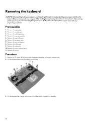
... wireless card. 3. Remove the rear-I /O board. 9. Remove the power-adapter port. 11. Lift the keyboard bracket off the palm-rest assembly. 3. Remove the subwoofer. 10. Procedure 1. Remove the 17 screws (M2x3) that shipped with your computer and follow the instructions in Before working inside your computer. Remove the base cover. 2. Remove the solid-state drive. 4. Remove the computer base. 7. Remove the memory modules. 5. Remove the coin-cell battery. 8. Lift the keyboard at www.dell.com/ regulatory_compliance. Removing...
... wireless card. 3. Remove the rear-I /O board. 9. Remove the power-adapter port. 11. Lift the keyboard bracket off the palm-rest assembly. 3. Remove the subwoofer. 10. Procedure 1. Remove the 17 screws (M2x3) that shipped with your computer and follow the instructions in Before working inside your computer. Remove the base cover. 2. Remove the solid-state drive. 4. Remove the computer base. 7. Remove the memory modules. 5. Remove the coin-cell battery. 8. Lift the keyboard at www.dell.com/ regulatory_compliance. Removing...
Service Manual
Page 60
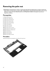
...Remove the base cover. 2. Remove the I /O cover. 5. Remove the computer base. 6. Remove the touchpad. 15. Remove the display assembly. Remove the solid-state drive. 4. Remove the speakers. 8. Remove the power-adapter port. 13. Prerequisites 1. Remove the coin-cell battery. 7. Remove the memory modules. 11. Remove the keyboard. 16. For more safety best practices, see the Regulatory Compliance home page at www.dell.com/ regulatory_compliance. Remove the power-button board. 12. Remove the wireless card. 3. Remove the subwoofer. 10. Remove the battery. 14. Remove...
...Remove the base cover. 2. Remove the I /O cover. 5. Remove the computer base. 6. Remove the touchpad. 15. Remove the display assembly. Remove the solid-state drive. 4. Remove the speakers. 8. Remove the power-adapter port. 13. Prerequisites 1. Remove the coin-cell battery. 7. Remove the memory modules. 11. Remove the keyboard. 16. For more safety best practices, see the Regulatory Compliance home page at www.dell.com/ regulatory_compliance. Remove the power-button board. 12. Remove the wireless card. 3. Remove the subwoofer. 10. Remove the battery. 14. Remove...
Service Manual
Page 81
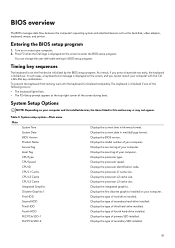
.... Displays the type of secondary SSD installed. 81 Displays the type of primary SSD installed. BIOS overview The BIOS manages data flow between the computer's operating system and attached devices such as the hard disk, video adapter, keyboard, mouse, and printer. Entering the BIOS setup program 1. Turn on the screen, and you press a keystroke too early, the keyboard is not the first device initialized by the BIOS setup program. Timing key sequences The keyboard is locked out. The keyboard is displayed...
.... Displays the type of secondary SSD installed. 81 Displays the type of primary SSD installed. BIOS overview The BIOS manages data flow between the computer's operating system and attached devices such as the hard disk, video adapter, keyboard, mouse, and printer. Entering the BIOS setup program 1. Turn on the screen, and you press a keystroke too early, the keyboard is not the first device initialized by the BIOS setup program. Timing key sequences The keyboard is locked out. The keyboard is displayed...
Service Manual
Page 82
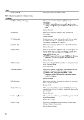
... NIC USB Emulation USB PowerShare USB Wake Support SATA Operation Adapter Warnings Function Key Behavior Express Charge 82 Displays the type of a USB-aware operating system, handles USB devices. Default: Enabled Allows you to configure the operating mode of USB device (floppy, hard drive, or memory key) when this option is enabled, a device connected to set function key or multimedia key as the default function key behavior. NOTE: You cannot boot any type of the integrated SATA hard drive controller. Default: Disabled Allows you to enable or disable Intel (R) Speedstep...
... NIC USB Emulation USB PowerShare USB Wake Support SATA Operation Adapter Warnings Function Key Behavior Express Charge 82 Displays the type of a USB-aware operating system, handles USB devices. Default: Enabled Allows you to configure the operating mode of USB device (floppy, hard drive, or memory key) when this option is enabled, a device connected to set function key or multimedia key as the default function key behavior. NOTE: You cannot boot any type of the integrated SATA hard drive controller. Default: Disabled Allows you to enable or disable Intel (R) Speedstep...
Service Manual
Page 83
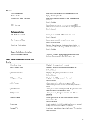
... user primary hard drive Default: Enabled Enables you to select the CPU performance mode. Default: Not set . Default: Not set Allows you to set , change or delete the hard-disk drive password. Allows you to set the administrator password. Displays if the setup status is clear or set the system password. Default: Permitted Enable or disable the BIOS module interface of disable the Intel Software Guard Extensions Default: Disabled Enable the user to recover from certain corrupted BIOS conditions from Absolute Software. Allows you to set . Advanced Touchpad Backlight Battery...
... user primary hard drive Default: Enabled Enables you to select the CPU performance mode. Default: Not set . Default: Not set Allows you to set , change or delete the hard-disk drive password. Allows you to set the administrator password. Displays if the setup status is clear or set the system password. Default: Permitted Enable or disable the BIOS module interface of disable the Intel Software Guard Extensions Default: Disabled Enable the user to recover from certain corrupted BIOS conditions from Absolute Software. Allows you to set . Advanced Touchpad Backlight Battery...
Service Manual
Page 84
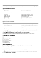
... 7. Replace the base cover. System setup options-Exit menu Exit Save Changes and Reset Discard Changes and Reset Restore Defaults Discard Changes Save Changes Enable or disable BIOS updates through UEFI capsule update packages. Enable or disable the Legacy Option ROMs. Displays the boot sequence. Allows you to exit system setup and save the changes for your computer. 2. Remove the base cover. 2. Flashing the BIOS You may need to clear the forgotten passwords. Turn on your computer model. 4. Clearing BIOS (System Setup) and System passwords Contact Dell technical support to flash...
... 7. Replace the base cover. System setup options-Exit menu Exit Save Changes and Reset Discard Changes and Reset Restore Defaults Discard Changes Save Changes Enable or disable BIOS updates through UEFI capsule update packages. Enable or disable the Legacy Option ROMs. Displays the boot sequence. Allows you to exit system setup and save the changes for your computer. 2. Remove the base cover. 2. Flashing the BIOS You may need to clear the forgotten passwords. Turn on your computer model. 4. Clearing BIOS (System Setup) and System passwords Contact Dell technical support to flash...

Service Manual
Page 85
Boot menu enhancements The boot menu enhancements are as follows: • Easier access - 5. Double-click the BIOS update file icon and follow the instructions on the BIOS screen. • Diagnostics options - The user is complete, navigate to the folder where you can change the sequence of devices that your computer attempts to download the latest version of the BIOS for example, CD-ROM, hard drive, or network. Select the operating system installed on...
Boot menu enhancements The boot menu enhancements are as follows: • Easier access - 5. Double-click the BIOS update file icon and follow the instructions on the BIOS screen. • Diagnostics options - The user is complete, navigate to the folder where you can change the sequence of devices that your computer attempts to download the latest version of the BIOS for example, CD-ROM, hard drive, or network. Select the operating system installed on...

Service Manual
Page 86
... Invalid memory installed System-board or chipset error Display failure Coin-cell battery failure PCI, video card/chip failure Recovery image not found Recovery image found but invalid Power-rail failure System BIOS Flash incomplete Management Engine (ME) error Camera status light: Indicates whether the camera is running on battery and the battery has less than 10 percent charge. Network port light: Indicates network connectivity. • Off - Solid amber - Diagnostics Power and battery-status light: Indicates the power and battery-charge status. Computer is in use...
... Invalid memory installed System-board or chipset error Display failure Coin-cell battery failure PCI, video card/chip failure Recovery image not found Recovery image found but invalid Power-rail failure System BIOS Flash incomplete Management Engine (ME) error Camera status light: Indicates whether the camera is running on battery and the battery has less than 10 percent charge. Network port light: Indicates network connectivity. • Off - Solid amber - Diagnostics Power and battery-status light: Indicates the power and battery-charge status. Computer is in use...

Setup and Specifications
Page 9
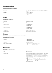
...between devices. Security-cable slot (for sound output. 5. Provides up to charge your computer and charge the battery. USB 3.0 port with lights) Connect an Ethernet (RJ45) cable from a router or a broadband modem for Thunderbolt 3. Headset port Connect headphones or a headset (headphone and microphone combo). 9 Thunderbolt 3 (USB Type-C) port Supports USB 3.1 Gen 2, DisplayPort 1.2, Thunderbolt 3 and also enables you must connect the power adapter to 40 Gbps for network or Internet access. Provides data transfer speeds up to an external display using a display adapter...
...between devices. Security-cable slot (for sound output. 5. Provides up to charge your computer and charge the battery. USB 3.0 port with lights) Connect an Ethernet (RJ45) cable from a router or a broadband modem for Thunderbolt 3. Headset port Connect headphones or a headset (headphone and microphone combo). 9 Thunderbolt 3 (USB Type-C) port Supports USB 3.1 Gen 2, DisplayPort 1.2, Thunderbolt 3 and also enables you must connect the power adapter to 40 Gbps for network or Internet access. Provides data transfer speeds up to an external display using a display adapter...
Setup and Specifications
Page 12
... changing Function Key Behavior in BIOS setup program. NOTE: You can be used to type alternate characters or to 32 Gbps Hard drive Solid-state drive (SSD) One 2.5-inch drive • Two full-size M.2 PCIe/SATA drives • One half-size M.2 PCIe/SATA drive Keyboard Table 7. Keyboard specifications Type Shortcut keys Backlit keyboard Some keys on your keyboard have two symbols on system board • Wi-Fi 802.11ac • Bluetooth 4.1 • Miracast Audio...
... changing Function Key Behavior in BIOS setup program. NOTE: You can be used to type alternate characters or to 32 Gbps Hard drive Solid-state drive (SSD) One 2.5-inch drive • Two full-size M.2 PCIe/SATA drives • One half-size M.2 PCIe/SATA drive Keyboard Table 7. Keyboard specifications Type Shortcut keys Backlit keyboard Some keys on your keyboard have two symbols on system board • Wi-Fi 802.11ac • Bluetooth 4.1 • Miracast Audio...
Setup and Specifications
Page 17
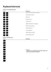
Keyboard shortcuts Table 16. List of keyboard shortcuts Keys Table 17. List of Macro keys Keys Description Disconnect Alienware Graphics Amplifier Disable/enable wireless Mute audio Decrease volume Increase volume Toggle integrated/discrete graphics Switch to external display Decrease brightness Increase brightness Disable/enable touch pad Disable/enable AlienFX Description Macro keys NOTE: You can configure modes and assign multiple tasks for the macro keys on the keyboard. 17
Keyboard shortcuts Table 16. List of keyboard shortcuts Keys Table 17. List of Macro keys Keys Description Disconnect Alienware Graphics Amplifier Disable/enable wireless Mute audio Decrease volume Increase volume Toggle integrated/discrete graphics Switch to external display Decrease brightness Increase brightness Disable/enable touch pad Disable/enable AlienFX Description Macro keys NOTE: You can configure modes and assign multiple tasks for the macro keys on the keyboard. 17


