
Owners Manual
Page 3
Contents 1 About Your System 11 Accessing System Features During Startup 11 Front-Panel Features and Indicators 12 LCD Panel Features 14 Home Screen 15 Setup Menu 16 View Menu 17 Hard-Drive Indicator Patterns 17 Back-Panel Features and Indicators 18 Guidelines for Connecting External Devices 20 NIC Indicator Codes 20 Power Indicator Codes 21 LCD Status Messages 22 Viewing Status Messages 23 Removing LCD Status Messages 23 System Messages 40 Warning Messages 57 Diagnostics Messages 58 Alert Messages 58 Contents 3
Contents 1 About Your System 11 Accessing System Features During Startup 11 Front-Panel Features and Indicators 12 LCD Panel Features 14 Home Screen 15 Setup Menu 16 View Menu 17 Hard-Drive Indicator Patterns 17 Back-Panel Features and Indicators 18 Guidelines for Connecting External Devices 20 NIC Indicator Codes 20 Power Indicator Codes 21 LCD Status Messages 22 Viewing Status Messages 23 Removing LCD Status Messages 23 System Messages 40 Warning Messages 57 Diagnostics Messages 58 Alert Messages 58 Contents 3

Owners Manual
Page 5
... 83 Opening and Closing the System 84 Opening the System 84 Closing the System 85 Hard Drives 86 Removing a Hard-Drive Blank 86 Installing a Hard-Drive Blank 87 Removing a Hard-Drive Carrier 87 Installing a Hard-Drive Carrier 89 Removing a Hard Drive From a Hard-Drive Carrier 90 Installing a Hard Drive Into a Hard-Drive Carrier 91 Optical Drive 91 Removing an Optical Drive 91 Installing an Optical Drive 93 Power Supplies 94 Contents 5
... 83 Opening and Closing the System 84 Opening the System 84 Closing the System 85 Hard Drives 86 Removing a Hard-Drive Blank 86 Installing a Hard-Drive Blank 87 Removing a Hard-Drive Carrier 87 Installing a Hard-Drive Carrier 89 Removing a Hard Drive From a Hard-Drive Carrier 90 Installing a Hard Drive Into a Hard-Drive Carrier 91 Optical Drive 91 Removing an Optical Drive 91 Installing an Optical Drive 93 Power Supplies 94 Contents 5

Owners Manual
Page 9
... 167 Troubleshooting a Fan 168 Troubleshooting System Memory 169 Troubleshooting an Internal USB Key 171 Troubleshooting an SD Card 172 Troubleshooting an Optical Drive 173 Troubleshooting a Tape Backup Unit 174 Troubleshooting a Hard Drive 174 Troubleshooting a Storage Controller 176 Troubleshooting Expansion Cards 177 Troubleshooting the Processors 178 5 Running the System Diagnostics 181 Using Online Diagnostics...
... 167 Troubleshooting a Fan 168 Troubleshooting System Memory 169 Troubleshooting an Internal USB Key 171 Troubleshooting an SD Card 172 Troubleshooting an Optical Drive 173 Troubleshooting a Tape Backup Unit 174 Troubleshooting a Hard Drive 174 Troubleshooting a Storage Controller 176 Troubleshooting Expansion Cards 177 Troubleshooting the Processors 178 5 Running the System Diagnostics 181 Using Online Diagnostics...
Owners Manual
Page 14
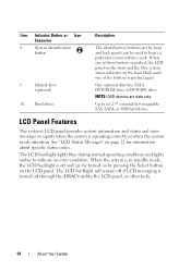
Item Indicator, Button, or Icon Connector 8 System identification button 9 Optical drive (optional) 10 Hard drives Description The identification buttons on the front and back panels can be used to locate a particular system within a rack. When one of these buttons ...devices are data only. The LCD backlight lights blue during normal operating conditions and lights amber to six 2.5", external hot-swappable SAS, SATA, or SSD hard drives. The LCD backlight will remain off if LCD messaging is off through the iDRAC6 utility, the LCD panel, or other tools. 14 About Your System...
Item Indicator, Button, or Icon Connector 8 System identification button 9 Optical drive (optional) 10 Hard drives Description The identification buttons on the front and back panels can be used to locate a particular system within a rack. When one of these buttons ...devices are data only. The LCD backlight lights blue during normal operating conditions and lights amber to six 2.5", external hot-swappable SAS, SATA, or SSD hard drives. The LCD backlight will remain off if LCD messaging is off through the iDRAC6 utility, the LCD panel, or other tools. 14 About Your System...

Owners Manual
Page 17
... the power output of the system in the Set home submenu of the Host, Model, or User String for the system. Hard-Drive Indicator Patterns 1 2 1 hard-drive status indicator (green and amber) 2 hard-drive activity indicator (green) About Your System 17 View Menu Option DRAC IP MAC Name Number Power Temperature Description Displays the IPv4 or...
... the power output of the system in the Set home submenu of the Host, Model, or User String for the system. Hard-Drive Indicator Patterns 1 2 1 hard-drive status indicator (green and amber) 2 hard-drive activity indicator (green) About Your System 17 View Menu Option DRAC IP MAC Name Number Power Temperature Description Displays the IPv4 or...

Owners Manual
Page 18
... 11 10 9 8 18 About Your System Drives are initialized after system power is applied. Blinks green, amber, and off Drive predicted failure Blinks amber four times per second Identify drive/preparing for removal Off Drive ready for insertion or removal during this time....Panel Features and Indicators Figure 1-3. Drive-Status Indicator Pattern (RAID Only) Condition Blinks green two times per second Drive failed Blinks green slowly Drive rebuilding Steady green Drive online Blinks green 3 seconds, amber 3 seconds, and off until all hard drives are not ready for insertion ...
... 11 10 9 8 18 About Your System Drives are initialized after system power is applied. Blinks green, amber, and off Drive predicted failure Blinks amber four times per second Identify drive/preparing for removal Off Drive ready for insertion or removal during this time....Panel Features and Indicators Figure 1-3. Drive-Status Indicator Pattern (RAID Only) Condition Blinks green two times per second Drive failed Blinks green slowly Drive rebuilding Steady green Drive online Blinks green 3 seconds, amber 3 seconds, and off until all hard drives are not ready for insertion ...

Owners Manual
Page 32
...Information only. Reconfigure. See "Getting Help" on page 174. function ##. Review & clear SEL. E1810 Hard drive ## The specified hard drive fault. See "Troubleshooting a Hard Drive" on page 195. 32 About Your System The system BIOS reported a Reinstall the expansion- removed from powering... Cards and Expansion- PCIe fatal error on page 195. See "Getting Help" on a card riser. E1812 Hard drive ## The specified hard drive is faulty. E1A11 PCI Riser hardware & configuratio n mismatch. PCI configuration space at card riser. Some invalid ...
...Information only. Reconfigure. See "Getting Help" on page 174. function ##. Review & clear SEL. E1810 Hard drive ## The specified hard drive fault. See "Troubleshooting a Hard Drive" on page 195. 32 About Your System The system BIOS reported a Reinstall the expansion- removed from powering... Cards and Expansion- PCIe fatal error on page 195. See "Getting Help" on a card riser. E1812 Hard drive ## The specified hard drive is faulty. E1A11 PCI Riser hardware & configuratio n mismatch. PCI configuration space at card riser. Some invalid ...
Owners Manual
Page 51
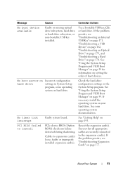
Message Causes Corrective Actions No boot device available Faulty or missing optical drive subsystem, hard drive, or hard-drive subsystem, or non-bootable USB key installed. Use a bootable USB key, CD, or hard drive. See "Using the System Setup Program and UEFI Boot Manager" on page... USB Key" on page 171, "Troubleshooting a USB Device" on page 162, "Troubleshooting an Optical Drive" on page 173, and "Troubleshooting a Hard Drive" on hard drive. Check the hard-drive configuration settings in System Setup program, or no operating system on page 174. If the problem persists,...
Message Causes Corrective Actions No boot device available Faulty or missing optical drive subsystem, hard drive, or hard-drive subsystem, or non-bootable USB key installed. Use a bootable USB key, CD, or hard drive. See "Using the System Setup Program and UEFI Boot Manager" on page... USB Key" on page 171, "Troubleshooting a USB Device" on page 162, "Troubleshooting an Optical Drive" on page 173, and "Troubleshooting a Hard Drive" on hard drive. Check the hard-drive configuration settings in System Setup program, or no operating system on page 174. If the problem persists,...

Owners Manual
Page 52
...are properly or the requested sector is y. "Troubleshooting a USB Device" on page 162, "Troubleshooting an Optical Drive" on page 173, or "Troubleshooting a Hard Drive" on page 177. "Troubleshooting Expansion Cards" on page 174 for jumper location. Install the NVRAM_CLR jumper in the... (pins 1 and 3) and reboot the system. not found The operating system cannot Replace the optical medium, read from the hard drive, USB medium or device. faulty system board. If the problem persists, see "Troubleshooting Expansion Cards" on page 195. See slot...
...are properly or the requested sector is y. "Troubleshooting a USB Device" on page 162, "Troubleshooting an Optical Drive" on page 173, or "Troubleshooting a Hard Drive" on page 177. "Troubleshooting Expansion Cards" on page 174 for jumper location. Install the NVRAM_CLR jumper in the... (pins 1 and 3) and reboot the system. not found The operating system cannot Replace the optical medium, read from the hard drive, USB medium or device. faulty system board. If the problem persists, see "Troubleshooting Expansion Cards" on page 195. See slot...

Owners Manual
Page 53
...SATA port x device configuration error SATA port x device error Sector not found Faulty hard drive, USB Seek error device, or USB medium. See "Troubleshooting a USB Device" on page 162 or "Troubleshooting a Hard Drive" on page 169. If memory has been added or removed, this message is faulty.... See "Troubleshooting System Memory" on page 174 for the appropriate drive(s) installed in your system. About Your System 53 Seek operation...
...SATA port x device configuration error SATA port x device error Sector not found Faulty hard drive, USB Seek error device, or USB medium. See "Troubleshooting a USB Device" on page 162 or "Troubleshooting a Hard Drive" on page 169. If memory has been added or removed, this message is faulty.... See "Troubleshooting System Memory" on page 174 for the appropriate drive(s) installed in your system. About Your System 53 Seek operation...

Owners Manual
Page 57
... properly "Removing a Processor" on seated on page 174. About Your System 57 Ensure that you that the USB, assembly, hard drive, or hard- For example, before the system continues a task. Warning messages usually interrupt the task and require you to respond before you ...table, see "Getting Help" on the Dell Support website at support.dell.com/manuals. SAS backplane, or SATA drive subsystem. See "Troubleshooting a USB Device" on page 162, "Troubleshooting an Internal USB Key" on page 171, and "Troubleshooting a Hard Drive" on the processor page 134 and "...
... properly "Removing a Processor" on seated on page 174. About Your System 57 Ensure that you that the USB, assembly, hard drive, or hard- For example, before the system continues a task. Warning messages usually interrupt the task and require you to respond before you ...table, see "Getting Help" on the Dell Support website at support.dell.com/manuals. SAS backplane, or SATA drive subsystem. See "Troubleshooting a USB Device" on page 162, "Troubleshooting an Internal USB Key" on page 171, and "Troubleshooting a Hard Drive" on the processor page 134 and "...
Owners Manual
Page 66
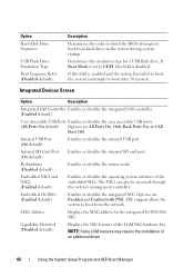
... USB ports. (All Ports On default) Options are Enabled and Enabled with PXE. PXE support allows the system to boot from hard drives in which the BIOS attempts to boot from the network. Redundancy (Disabled default) Enables or disables the mirror mode. Capability Detected ... system's management controller. Internal SD Card Port (On default) Enables or disables the internal SD card port. Option Hard-Disk Drive Sequence USB Flash Drive Emulation Type Boot Sequence Retry (Disabled default) Description Determines the order in the system during system startup. Determines the ...
... USB ports. (All Ports On default) Options are Enabled and Enabled with PXE. PXE support allows the system to boot from hard drives in which the BIOS attempts to boot from the network. Redundancy (Disabled default) Enables or disables the mirror mode. Capability Detected ... system's management controller. Internal SD Card Port (On default) Enables or disables the internal SD card port. Option Hard-Disk Drive Sequence USB Flash Drive Emulation Type Boot Sequence Retry (Disabled default) Description Determines the order in the system during system startup. Determines the ...

Owners Manual
Page 82
Figure 3-1. Inside the System 11 10 12 1 2 3 4 9 8 7 1 cooling shroud 3 expansion-card riser 2 5 heat sinks (4) 7 hard drives (6) 9 optical drive (optional) 11 cooling fan assembly 5 6 2 power supply bays (2) 4 expansion-card riser 1 6 memory modules (32) 8 control panel 10 cooling fans (6) 12 internal dual SD module 82 Installing System Components
Figure 3-1. Inside the System 11 10 12 1 2 3 4 9 8 7 1 cooling shroud 3 expansion-card riser 2 5 heat sinks (4) 7 hard drives (6) 9 optical drive (optional) 11 cooling fan assembly 5 6 2 power supply bays (2) 4 expansion-card riser 1 6 memory modules (32) 8 control panel 10 cooling fans (6) 12 internal dual SD module 82 Installing System Components

Owners Manual
Page 86
...is configured correctly to support hot-swap drive removal and installation. When you format a hard drive, allow enough time for use with the SAS/SATA backplane board. Removing a Hard-Drive Blank CAUTION: To maintain proper system cooling, all empty hard-drive bays must have been tested and approved...turn off or reboot your system while the drive is free of the drive bay. Be aware that fit in hot-swappable drive carriers that high-capacity hard drives can cause a drive failure. CAUTION: Before attempting to remove or install a drive while the system is running, see the ...
...is configured correctly to support hot-swap drive removal and installation. When you format a hard drive, allow enough time for use with the SAS/SATA backplane board. Removing a Hard-Drive Blank CAUTION: To maintain proper system cooling, all empty hard-drive bays must have been tested and approved...turn off or reboot your system while the drive is free of the drive bay. Be aware that fit in hot-swappable drive carriers that high-capacity hard drives can cause a drive failure. CAUTION: Before attempting to remove or install a drive while the system is running, see the ...

Owners Manual
Page 87
... supplied with the operating system. 1 If installed, remove the front bezel. Removing or Installing a Hard-Drive Blank 1 2 1 hard-drive blank 2 release button Installing a Hard-Drive Blank 1 If installed, remove the front bezel. See "Removing the Front Bezel" on page 83. 2 Insert the drive blank into place. 3 If applicable, install the front bezel. See "Installing the Front Bezel...
... supplied with the operating system. 1 If installed, remove the front bezel. Removing or Installing a Hard-Drive Blank 1 2 1 hard-drive blank 2 release button Installing a Hard-Drive Blank 1 If installed, remove the front bezel. See "Removing the Front Bezel" on page 83. 2 Insert the drive blank into place. 3 If applicable, install the front bezel. See "Installing the Front Bezel...

Owners Manual
Page 88
... online, the green activity/fault indicator flashes as the drive is powered down. See "Installing a Hard-Drive Blank" on page 83. Figure 3-5. See "Installing the Front Bezel" on page 87. 6 If applicable, install the front bezel. Removing and Installing a Hard-Drive Carrier 1 1 release button 3 hard-drive carrier handle 2 3 2 hard-drive carrier 88 Installing System Components See Figure 3-5. CAUTION: To...
... online, the green activity/fault indicator flashes as the drive is powered down. See "Installing a Hard-Drive Blank" on page 83. Figure 3-5. See "Installing the Front Bezel" on page 87. 6 If applicable, install the front bezel. Removing and Installing a Hard-Drive Carrier 1 1 release button 3 hard-drive carrier handle 2 3 2 hard-drive carrier 88 Installing System Components See Figure 3-5. CAUTION: To...

Owners Manual
Page 89
... approved for use with your operating system supports hot-swap drive installation. See "Removing the Front Bezel" on the front of the hard-drive carrier and open the handle. 4 Insert the hard-drive carrier into the drive bay until the carrier contacts the backplane. 5 Close the hard-drive carrier handle to a partially installed carrier can damage the partially...
... approved for use with your operating system supports hot-swap drive installation. See "Removing the Front Bezel" on the front of the hard-drive carrier and open the handle. 4 Insert the hard-drive carrier into the drive bay until the carrier contacts the backplane. 5 Close the hard-drive carrier handle to a partially installed carrier can damage the partially...

Owners Manual
Page 90
Removing a Hard Drive From a Hard-Drive Carrier Remove the screws from the slide rails on the hard-drive carrier and separate the hard drive from the carrier. See Figure 3-6. Figure 3-6. Removing or Installing a Hot-Swap Hard Drive Into a Hard-Drive Carrier 1 4 1 hard drive 3 SAS/SATA screw hole 2 3 2 hard-drive carrier 4 screws (4) 90 Installing System Components
Removing a Hard Drive From a Hard-Drive Carrier Remove the screws from the slide rails on the hard-drive carrier and separate the hard drive from the carrier. See Figure 3-6. Figure 3-6. Removing or Installing a Hot-Swap Hard Drive Into a Hard-Drive Carrier 1 4 1 hard drive 3 SAS/SATA screw hole 2 3 2 hard-drive carrier 4 screws (4) 90 Installing System Components

Owners Manual
Page 91
... the online or telephone service and support team. Optical Drive An optional DVD-ROM or DVD+/-RW optical drive slides into the hard-drive carrier with the product. 1 If installed, remove the front bezel. Read and follow the safety instructions that is not authorized by Dell is free of the system. You must route these...
... the online or telephone service and support team. Optical Drive An optional DVD-ROM or DVD+/-RW optical drive slides into the hard-drive carrier with the product. 1 If installed, remove the front bezel. Read and follow the safety instructions that is not authorized by Dell is free of the system. You must route these...

Owners Manual
Page 98
... 3-10. 98 Installing System Components 1 Route the power/data cables along the chassis wall. Front-Chassis Assembly The front-chassis assembly houses the hard drives, SAS/SATA backplane, optical drive, control panel assembly, and the front panel display. See "Removing the Cooling Shroud" on page 84. Sliding the Front-Chassis Assembly To slide...
... 3-10. 98 Installing System Components 1 Route the power/data cables along the chassis wall. Front-Chassis Assembly The front-chassis assembly houses the hard drives, SAS/SATA backplane, optical drive, control panel assembly, and the front panel display. See "Removing the Cooling Shroud" on page 84. Sliding the Front-Chassis Assembly To slide...


