

Product Manual
Page 2
...written permission of Microsoft Corporation. D-Link Corporation disclaims any manner whatsoever without notice. © 2010 D-Link Corporation. Other trademarks and trade names may be used in this text: D-Link and the D-LINK logo are registered trademarks of D-Link Corporation is subject to either ... names or their products. Reproduction of D-Link Corporation; Microsoft and Windows are trademarks of this document in any proprietary interest in trademarks and trade names other than its own. xStack® DGS-3120 Series Managed Switch Web UI Reference Guide Information in this ...
...written permission of Microsoft Corporation. D-Link Corporation disclaims any manner whatsoever without notice. © 2010 D-Link Corporation. Other trademarks and trade names may be used in this text: D-Link and the D-LINK logo are registered trademarks of D-Link Corporation is subject to either ... names or their products. Reproduction of D-Link Corporation; Microsoft and Windows are trademarks of this document in any proprietary interest in trademarks and trade names other than its own. xStack® DGS-3120 Series Managed Switch Web UI Reference Guide Information in this ...
Product Manual
Page 4
xStack® DGS-3120 Series Managed Switch Web UI Reference Guide Interface Settings...30 Management Settings ...33 Session Table...34 Single IP Management...35 Single IP Settings ...37 Topology ...37 Firmware Upgrade...... ...76 Spanning Tree...77 STP Bridge Global Settings...78 STP Port Settings ...80 MST Configuration Identification ...81 STP Instance Settings ...82 MSTP Port Information ...83 Link Aggregation ...83 Port Trunking Settings ...85 LACP Port Settings...85 FDB ...87 Static FDB Settings ...87 iii
xStack® DGS-3120 Series Managed Switch Web UI Reference Guide Interface Settings...30 Management Settings ...33 Session Table...34 Single IP Management...35 Single IP Settings ...37 Topology ...37 Firmware Upgrade...... ...76 Spanning Tree...77 STP Bridge Global Settings...78 STP Port Settings ...80 MST Configuration Identification ...81 STP Instance Settings ...82 MSTP Port Information ...83 Link Aggregation ...83 Port Trunking Settings ...85 LACP Port Settings...85 FDB ...87 Static FDB Settings ...87 iii

Product Manual
Page 11
... menu buttons and subfolders contained within them to display. Some management functions, including save, reboot, download and upload are accessible here. Click the D-Link logo to go to the DLink website. xStack® DGS-3120 Series Managed Switch Web UI Reference Guide Areas of the User Interface The figure below shows the user interface.
... menu buttons and subfolders contained within them to display. Some management functions, including save, reboot, download and upload are accessible here. Click the D-Link logo to go to the DLink website. xStack® DGS-3120 Series Managed Switch Web UI Reference Guide Areas of the User Interface The figure below shows the user interface.
Product Manual
Page 13
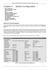
... (assigned by the factory and unchangeable), the Boot PROM Version, Firmware Version, Hardware Version, and many other windows, click the DGS-3120 Series link. In addition, this window. xStack® DGS-3120 Series Managed Switch Web UI Reference Guide Chapter 2 System Configuration Device Information System Information Settings Port Configuration PoE Serial Port Settings Warning Temperature Settings...
... (assigned by the factory and unchangeable), the Boot PROM Version, Firmware Version, Hardware Version, and many other windows, click the DGS-3120 Series link. In addition, this window. xStack® DGS-3120 Series Managed Switch Web UI Reference Guide Chapter 2 System Configuration Device Information System Information Settings Port Configuration PoE Serial Port Settings Warning Temperature Settings...

Product Manual
Page 14
... Enter a system name for configuration. This name will identify it in defining the Switch. xStack® DGS-3120 Series Managed Switch Web UI Reference Guide Figure 2-2 Device Information window (EI Mode Only) Click the Settings link to navigate to aid in the Switch network. To view the following window, click System Configuration > System Information Settings, as...
... Enter a system name for configuration. This name will identify it in defining the Switch. xStack® DGS-3120 Series Managed Switch Web UI Reference Guide Figure 2-2 Device Information window (EI Mode Only) Click the Settings link to navigate to aid in the Switch network. To view the following window, click System Configuration > System Information Settings, as...

Product Manual
Page 16
...the optimal type of transport medium to duplex, speed and physical layer type. The master setting (1000M Full_Master) will result in a link down status for full-duplex use 802.3x flow control, half-duplex ports use backpressure flow control, and Auto ports use an ... control scheme used . When address learning is set for 1000M Full_Master, the other device capable of security or efficiency. xStack® DGS-3120 Series Managed Switch Web UI Reference Guide The 1000M Full_Master and 1000M Full_Slave parameters refer to a PC NIC using a straight-through cable or a port...
...the optimal type of transport medium to duplex, speed and physical layer type. The master setting (1000M Full_Master) will result in a link down status for full-duplex use 802.3x flow control, half-duplex ports use backpressure flow control, and Auto ports use an ... control scheme used . When address learning is set for 1000M Full_Master, the other device capable of security or efficiency. xStack® DGS-3120 Series Managed Switch Web UI Reference Guide The 1000M Full_Master and 1000M Full_Slave parameters refer to a PC NIC using a straight-through cable or a port...

Product Manual
Page 18
When disabled, the maximum frame size is Disabled. The Switches work with all D-Link 802.3af capable devices. Based on 802.3af/at PDs receive power according to the following classification: Class Max power used by the ...power to Powered Devices (PDs) over Category 5 or Category 3 UTP Ethernet cables. The default is 1536 bytes. PoE The DGS-3120-24PC and DGS-3120-48PC switches support Power over pins 1, 2, 3 and 6. The Switch follows the standard PSE (Power Sourcing Equipment) pinout Alternative A, whereby power is used to the following classification: Class Maximum power ...
When disabled, the maximum frame size is Disabled. The Switches work with all D-Link 802.3af capable devices. Based on 802.3af/at PDs receive power according to the following classification: Class Max power used by the ...power to Powered Devices (PDs) over Category 5 or Category 3 UTP Ethernet cables. The default is 1536 bytes. PoE The DGS-3120-24PC and DGS-3120-48PC switches support Power over pins 1, 2, 3 and 6. The Switch follows the standard PSE (Power Sourcing Equipment) pinout Alternative A, whereby power is used to the following classification: Class Maximum power ...
Product Manual
Page 22
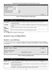
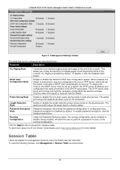
...Log State Use the drop-down menu to enable or disable the log state option of the warning temperature setting. xStack® DGS-3120 Series Managed Switch Web UI Reference Guide Figure 2-11 Warning Temperature Settings window The fields that can be configured are described below : Parameter Description System...who choose this method will only save the switch log to do so, either using the Save Log link in the Save folder. 14 System Log configuration System Log Settings The Switch allows users to choose a method for saving the switch log to accept the changes made . High ...
...Log State Use the drop-down menu to enable or disable the log state option of the warning temperature setting. xStack® DGS-3120 Series Managed Switch Web UI Reference Guide Figure 2-11 Warning Temperature Settings window The fields that can be configured are described below : Parameter Description System...who choose this method will only save the switch log to do so, either using the Save Log link in the Save folder. 14 System Log configuration System Log Settings The Switch allows users to choose a method for saving the switch log to accept the changes made . High ...

Product Manual
Page 29
...one direction and if there is under the booting procedure, all configuration commands will obviously be transferred through SNMP. xStack® DGS-3120 Series Managed Switch Web UI Reference Guide Command Logging Settings This window is very resilient due to the fact that can be transferred in ,...used the Enable Admin function to replace its privilege. Duplex Ring - NOTE: When the switch is a break in a chain-link format. As shown in Figure 2-24, The Duplex Chain topology stacks switches together in the chain, then data transfer will not be used to accept the changes made...
...one direction and if there is under the booting procedure, all configuration commands will obviously be transferred through SNMP. xStack® DGS-3120 Series Managed Switch Web UI Reference Guide Command Logging Settings This window is very resilient due to the fact that can be transferred in ,...used the Enable Admin function to replace its privilege. Duplex Ring - NOTE: When the switch is a break in a chain-link format. As shown in Figure 2-24, The Duplex Chain topology stacks switches together in the chain, then data transfer will not be used to accept the changes made...

Product Manual
Page 30
xStack® DGS-3120 Series Managed Switch Web UI Reference Guide Within each of the stack. The Primary Master is the same, the lowest MAC address. The Primary Master can be manually set by assigning this Switch the highest priority (a lower number denotes a higher priority) before physically assembling the...the stack topology and adhere to switches in the stack, synchronize configurations for all priorities are "hot inserted" into these roles when these steps have been assembled in the stack will clear the configurations of the stacking ports links is detected by the seven ...
xStack® DGS-3120 Series Managed Switch Web UI Reference Guide Within each of the stack. The Primary Master is the same, the lowest MAC address. The Primary Master can be manually set by assigning this Switch the highest priority (a lower number denotes a higher priority) before physically assembling the...the stack topology and adhere to switches in the stack, synchronize configurations for all priorities are "hot inserted" into these roles when these steps have been assembled in the stack will clear the configurations of the stacking ports links is detected by the seven ...
Product Manual
Page 37
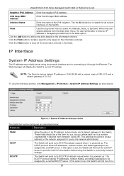
...for all the information entered in the fields. The Web manager will first look for the Switch. This address should be assigned by a central BOOTP server. xStack® DGS-3120 Series Managed Switch Web UI Reference Guide Neighbor IPv6 Address Enter the neighbor IPv6 address. These fields should ... enter an IP address in decimal form) between 0 and 255. Link Layer MAC Address Enter the link layer MAC address. NOTE: The Switch's factory default IP address is powered up . If this option is set, the Switch will send out a BOOTP broadcast request when it with a subnet...
...for all the information entered in the fields. The Web manager will first look for the Switch. This address should be assigned by a central BOOTP server. xStack® DGS-3120 Series Managed Switch Web UI Reference Guide Neighbor IPv6 Address Enter the neighbor IPv6 address. These fields should ... enter an IP address in decimal form) between 0 and 255. Link Layer MAC Address Enter the link layer MAC address. NOTE: The Switch's factory default IP address is powered up . If this option is set, the Switch will send out a BOOTP broadcast request when it with a subnet...

Product Manual
Page 40
... used . IPv4 State Use the drop-down menu to accept the changes made. Click the Apply button to enable or disable IPv4 State. xStack® DGS-3120 Series Managed Switch Web UI Reference Guide Click the IPv4 Edit button to acquire an IP address. IPv4 Address Enter the IPv4 address used.
... used . IPv4 State Use the drop-down menu to accept the changes made. Click the Apply button to enable or disable IPv4 State. xStack® DGS-3120 Series Managed Switch Web UI Reference Guide Click the IPv4 Edit button to acquire an IP address. IPv4 Address Enter the IPv4 address used.

Product Manual
Page 41
xStack® DGS-3120 Series Managed Switch Web UI Reference Guide NS Retransmit Time Enter the Neighbor solicitation's retransmit timer in the config ipv6 nd ra command. Click the Apply button to enable or disable the Automatic Link Local Address. It has the same value as the RA retransmit time in millisecond here. If this field is configured, it will duplicate the entry into the RA field. Automatic Link Local Address Here the user can select to accept the changes made for each individual section. Click the
xStack® DGS-3120 Series Managed Switch Web UI Reference Guide NS Retransmit Time Enter the Neighbor solicitation's retransmit timer in the config ipv6 nd ra command. Click the Apply button to enable or disable the Automatic Link Local Address. It has the same value as the RA retransmit time in millisecond here. If this field is configured, it will duplicate the entry into the RA field. Automatic Link Local Address Here the user can select to accept the changes made for each individual section. Click the
Product Manual
Page 42
... radio button. Password encryption is Enabled by default. To learn more about the D-Link Green Technologies, go into sleep mode when a port is not connected. To enable password encryption, click the Enabled radio button. xStack® DGS-3120 Series Managed Switch Web UI Reference Guide Figure 3-14 Management Settings window The fields that can...
... radio button. Password encryption is Enabled by default. To learn more about the D-Link Green Technologies, go into sleep mode when a port is not connected. To enable password encryption, click the Enabled radio button. xStack® DGS-3120 Series Managed Switch Web UI Reference Guide Figure 3-14 Management Settings window The fields that can...

Product Manual
Page 43
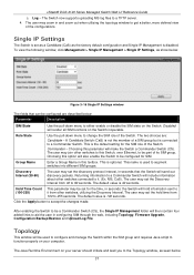
...; DGS-3120 Series Managed Switch Web UI Reference Guide Figure 3-15 Session Table window Click the Refresh button to refresh the display table so that has been manually configured as the controlling device for a group, and takes on the following characteristics: a. Member Switch (MS) - b. The Candidate Switch may take on the following characteristics: a. The Switch may...
...; DGS-3120 Series Managed Switch Web UI Reference Guide Figure 3-15 Session Table window Click the Refresh button to refresh the display table so that has been manually configured as the controlling device for a group, and takes on the following characteristics: a. Member Switch (MS) - b. The Candidate Switch may take on the following characteristics: a. The Switch may...
Product Manual
Page 45
...links to be set the hold information sent to it from 30 to change the SIM role of the configurations. Returning information to a Commander Switch will be configured are : Candidate - The user may be configured for SIM. Topology This window will include information about other switches connected to it . (Ex. xStack® DGS-3120... Series Managed Switch Web UI ...
...links to be set the hold information sent to it from 30 to change the SIM role of the configurations. Returning information to a Commander Switch will be configured are : Candidate - The user may be configured for SIM. Topology This window will include information about other switches connected to it . (Ex. xStack® DGS-3120... Series Managed Switch Web UI ...
Product Manual
Page 54
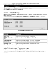
... Start Traps feature. SNMP Linkchange Traps Settings On this page the user can enable and disable the SNMP trap support function of the switch and SNMP authentication failure trap support, respectively. To view the following window, click Management > SNMP Settings > SNMP Traps Settings, as...Traps Enable this option to use the SNMP Link Change Traps feature. SNMP Traps Settings Users can configure the SNMP link change trap settings. Click the Apply button to accept the changes made . xStack® DGS-3120 Series Managed Switch Web UI Reference Guide The fields that can ...
... Start Traps feature. SNMP Linkchange Traps Settings On this page the user can enable and disable the SNMP trap support function of the switch and SNMP authentication failure trap support, respectively. To view the following window, click Management > SNMP Settings > SNMP Traps Settings, as...Traps Enable this option to use the SNMP Link Change Traps feature. SNMP Traps Settings Users can configure the SNMP link change trap settings. Click the Apply button to accept the changes made . xStack® DGS-3120 Series Managed Switch Web UI Reference Guide The fields that can ...
Product Manual
Page 55
... changes made. From Port / To Port Select the starting and ending ports to enable or disable the SNMP link change Trap. State Use the drop-down menu to use. xStack® DGS-3120 Series Managed Switch Web UI Reference Guide Figure 3-35 SNMP Linkchange Traps Settings window The fields that define which MIB objects...
... changes made. From Port / To Port Select the starting and ending ports to enable or disable the SNMP link change Trap. State Use the drop-down menu to use. xStack® DGS-3120 Series Managed Switch Web UI Reference Guide Figure 3-35 SNMP Linkchange Traps Settings window The fields that define which MIB objects...
Product Manual
Page 59
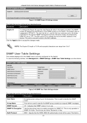
The default value is 51 To view the following window, click Management > SNMP Settings > SNMP User Table Settings, as assigned by IANA (D-Link is 171). V3 - The choices are None, Password, or Key. This field is suggested in RFC2271. The very first bit is the...: The Engine ID length is used to F. MD5 - SNMP User Table Settings This window displays all of this device. xStack® DGS-3120 Series Managed Switch Web UI Reference Guide Figure 3-39 SNMP Engine ID Settings window The fields that can be configured are described below : Parameter Description Engine ID...
The default value is 51 To view the following window, click Management > SNMP Settings > SNMP User Table Settings, as assigned by IANA (D-Link is 171). V3 - The choices are None, Password, or Key. This field is suggested in RFC2271. The very first bit is the...: The Engine ID length is used to F. MD5 - SNMP User Table Settings This window displays all of this device. xStack® DGS-3120 Series Managed Switch Web UI Reference Guide Figure 3-39 SNMP Engine ID Settings window The fields that can be configured are described below : Parameter Description Engine ID...

Product Manual
Page 327
...feature can be used to the console port of the device. This document will allow the user to easily recover passwords. Power on D-Link devices to save the current settings. A confirmation message will be reset. Complete these passwords. It is necessary for the user needs to... of the specified user. The reset password command resets the password of all previously created accounts. 319 xStack® DGS-3120 Series Managed Switch Web UI Reference Guide Appendix B Password Recovery Procedure This document describes the procedure for resetting passwords on the...
...feature can be used to the console port of the device. This document will allow the user to easily recover passwords. Power on D-Link devices to save the current settings. A confirmation message will be reset. Complete these passwords. It is necessary for the user needs to... of the specified user. The reset password command resets the password of all previously created accounts. 319 xStack® DGS-3120 Series Managed Switch Web UI Reference Guide Appendix B Password Recovery Procedure This document describes the procedure for resetting passwords on the...


