
User Manual
Page 2
... Information ...19 Password Settings...19 i Table of Contents D-Link Web Smart Switch User Manual Table of Contents Table of Contents ...i About This Guide ...1 Terms/Usage...1 Copyright and Trademarks ...1 1 Product Introduction ...2 DGS-1500-20 ...3 Front Panel ...3 Rear Panel...3 DGS-1500-28 ...3 Front Panel ...3 Rear Panel...4 DGS-1500-28P...4 Front Panel ...4 Rear Panel...5 DGS-1500-52 ...5 Front Panel ...5 Rear Panel...5 2 Hardware Installation...
... Information ...19 Password Settings...19 i Table of Contents D-Link Web Smart Switch User Manual Table of Contents Table of Contents ...i About This Guide ...1 Terms/Usage...1 Copyright and Trademarks ...1 1 Product Introduction ...2 DGS-1500-20 ...3 Front Panel ...3 Rear Panel...3 DGS-1500-28 ...3 Front Panel ...3 Rear Panel...4 DGS-1500-28P...4 Front Panel ...4 Rear Panel...5 DGS-1500-52 ...5 Front Panel ...5 Rear Panel...5 2 Hardware Installation...
User Manual
Page 3
Table of Contents D-Link Web Smart Switch User Manual SNMP Settings ...20 Web-based Management ...21 Tool Bar > Save Menu ...22 Save Configuration ...22 Save Log ...22 Tool Bar > ... > MST Configuration Identification 43 L2 Functions > Spanning Tree > STP Instance Settings 44 L2 Functions > Spanning Tree > MSTP Port Information 45 L2 Functions > Link Aggregation > Port Trunking 45 L2 Functions > Link Aggregation > LACP Port Settings 46 L2 Functions > Multicast > IGMP Snooping 46 L2 Functions > Multicast > Multicast Forwarding 48 L2 Functions > Multicast > Multicast Filtering...
Table of Contents D-Link Web Smart Switch User Manual SNMP Settings ...20 Web-based Management ...21 Tool Bar > Save Menu ...22 Save Configuration ...22 Save Log ...22 Tool Bar > ... > MST Configuration Identification 43 L2 Functions > Spanning Tree > STP Instance Settings 44 L2 Functions > Spanning Tree > MSTP Port Information 45 L2 Functions > Link Aggregation > Port Trunking 45 L2 Functions > Link Aggregation > LACP Port Settings 46 L2 Functions > Multicast > IGMP Snooping 46 L2 Functions > Multicast > Multicast Forwarding 48 L2 Functions > Multicast > Multicast Filtering...
User Manual
Page 4
Table of Contents D-Link Web Smart Switch User Manual L2 Functions > LLDP > LLDP Port Settings 51 L2 Functions > LLDP > 802.1 Extension TLV 52 L2 Functions > LLDP > 802.3 Extension TLV ......72 AAA > 802.1X > 802.1X User...73 ACL > ACL Wizard ...73 ACL > Access Profile List ...75 ACL > ACL Finder ...85 PoE > PoE Global Settings (DGS-1500-28P only 85 PoE > PoE Port Settings (DGS-1500-28P only 86 SNMP > Trap to SmartConsole...87 SNMP > SNMP > SNMP Global Settings 87 SNMP > SNMP > SNMP User ...88 iii
Table of Contents D-Link Web Smart Switch User Manual L2 Functions > LLDP > LLDP Port Settings 51 L2 Functions > LLDP > 802.1 Extension TLV 52 L2 Functions > LLDP > 802.3 Extension TLV ......72 AAA > 802.1X > 802.1X User...73 ACL > ACL Wizard ...73 ACL > Access Profile List ...75 ACL > ACL Finder ...85 PoE > PoE Global Settings (DGS-1500-28P only 85 PoE > PoE Port Settings (DGS-1500-28P only 86 SNMP > Trap to SmartConsole...87 SNMP > SNMP > SNMP Global Settings 87 SNMP > SNMP > SNMP User ...88 iii
User Manual
Page 5
... Physical & Environment ...105 RPS Support...105 Emission (EMI) Certifications ...105 Safety Certifications...105 Features ...105 L2 Features ...105 L3 Features ...106 D-Link Green Technology ...106 VLAN ...106 QoS (Quality of Contents D-Link Web Smart Switch User Manual SNMP > SNMP > SNMP Group ...89 SNMP > SNMP > SNMP View ...89 SNMP > SNMP > SNMP Community...90...
... Physical & Environment ...105 RPS Support...105 Emission (EMI) Certifications ...105 Safety Certifications...105 Features ...105 L2 Features ...105 L3 Features ...106 D-Link Green Technology ...106 VLAN ...106 QoS (Quality of Contents D-Link Web Smart Switch User Manual SNMP > SNMP > SNMP Group ...89 SNMP > SNMP > SNMP View ...89 SNMP > SNMP > SNMP Community...90...

User Manual
Page 6
...Management step-by -step hardware installation procedures. 2. Copyright and Trademarks Information in the document. D-Link Corporation disclaims any manner whatever without notice. © 2011 D-Link Corporation. Hardware Installation: Step-by -step. Some technologies refer to other than its components, ... Specification sections for basic switch installation and settings. 3. About This Guide D-Link Web Smart Switch User Manual About This Guide This guide provides instructions to install the D-Link Gigabit SmartPro Switch DGS-1500-20/28/28P/52, how to use of the device.
...Management step-by -step hardware installation procedures. 2. Copyright and Trademarks Information in the document. D-Link Corporation disclaims any manner whatever without notice. © 2011 D-Link Corporation. Hardware Installation: Step-by -step. Some technologies refer to other than its components, ... Specification sections for basic switch installation and settings. 3. About This Guide D-Link Web Smart Switch User Manual About This Guide This guide provides instructions to install the D-Link Gigabit SmartPro Switch DGS-1500-20/28/28P/52, how to use of the device.

User Manual
Page 7
...28P, D-Link Green Technology offers Time-based PoE feature to shut down to remotely control their network, using the Command Line Interface (CLI). 2 The new generation of the smart switches. QoS. The switches within the same L2 network segment connected to the user's local PC are displayed on DGS-1500... series such as a password change the IP address of the PC and provide easy initial settings of D-Link Web Smart Switches provides growing businesses with VLAN and 802.1p traffic and IPv6 ...
...28P, D-Link Green Technology offers Time-based PoE feature to shut down to remotely control their network, using the Command Line Interface (CLI). 2 The new generation of the smart switches. QoS. The switches within the same L2 network segment connected to the user's local PC are displayed on DGS-1500... series such as a password change the IP address of the PC and provide easy initial settings of D-Link Web Smart Switches provides growing businesses with VLAN and 802.1p traffic and IPv6 ...

User Manual
Page 8
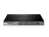
...the status, or send out traps of abnormal events. Front Panel Figure 1.1 - Port Link/Act/Speed LED (1-16, 17F, 18F, 19F, 20F): The port LEDs indicate a network link through the corresponding port. DGS-1500-28 Front Panel 3 SFP ports for management in amber, it is connected to -use... UL listed Optical Transceiver product, Rated Laser Class I. 3.3Vdc Rear Panel Figure 1.2 - DGS-1500-28 24-Port 10/100/1000Mbps plus 4 1000Base-T/SFP ports SmartPro Switch. D-Link Web Smart Switches also come with the D-View plug-in module that works with other third-party devices ...
...the status, or send out traps of abnormal events. Front Panel Figure 1.1 - Port Link/Act/Speed LED (1-16, 17F, 18F, 19F, 20F): The port LEDs indicate a network link through the corresponding port. DGS-1500-28 Front Panel 3 SFP ports for management in amber, it is connected to -use... UL listed Optical Transceiver product, Rated Laser Class I. 3.3Vdc Rear Panel Figure 1.2 - DGS-1500-28 24-Port 10/100/1000Mbps plus 4 1000Base-T/SFP ports SmartPro Switch. D-Link Web Smart Switches also come with the D-View plug-in module that works with other third-party devices ...

User Manual
Page 9
DGS-1500-28P 24-Port 10/100/1000Mbps plus 4 1000Base-T/SFP ports SmartPro PoE Switch. Front Panel Figure 1.5 - Port Link/Act/Speed LED (1-24, 25F, 26F, 27F, 28F): The Link/Act/Speed LED flashes, which indicates a network link through the corresponding port. When it has a green light it is inserted to 28. When optical ... 78 Watts. Mode: By pressing the Mode button, the Port LED will be lost . NOTE: On DGS-1500-28P, the SFP ports are shared with normal RJ-45 ports 25 to SFP port and link up, the RJ-45 port cannot be lost . Fan: The Fan LED lights green when fans work...
DGS-1500-28P 24-Port 10/100/1000Mbps plus 4 1000Base-T/SFP ports SmartPro PoE Switch. Front Panel Figure 1.5 - Port Link/Act/Speed LED (1-24, 25F, 26F, 27F, 28F): The Link/Act/Speed LED flashes, which indicates a network link through the corresponding port. When it has a green light it is inserted to 28. When optical ... 78 Watts. Mode: By pressing the Mode button, the Port LED will be lost . NOTE: On DGS-1500-28P, the SFP ports are shared with normal RJ-45 ports 25 to SFP port and link up, the RJ-45 port cannot be lost . Fan: The Fan LED lights green when fans work...

User Manual
Page 10
...Panel Figure 1.8 - Front Panel Figure 1.7 - Port Link/Act/Speed LED (1-48, 49F, 50F, 51F, 52F): The Link/Act/Speed LED flashes, which indicates a network link through the corresponding port. When a port has an amber light, this port. 5 DGS-1500-52 Rear Panel Power: Connect the supplied AC power ... cord. CAUTION: The MiniGBIC ports should use UL listed Optical Transceiver product, Rated Laser Class I. 3.3Vdc. DGS-1500-28P Rear Panel Power: The power port is running on 1000M. DGS-1500-52 48-Port 10/100/1000Mbps plus 4 100/1000FX SFP Slot SmartPro Switch. When it has a green...
...Panel Figure 1.8 - Front Panel Figure 1.7 - Port Link/Act/Speed LED (1-48, 49F, 50F, 51F, 52F): The Link/Act/Speed LED flashes, which indicates a network link through the corresponding port. When a port has an amber light, this port. 5 DGS-1500-52 Rear Panel Power: Connect the supplied AC power ... cord. CAUTION: The MiniGBIC ports should use UL listed Optical Transceiver product, Rated Laser Class I. 3.3Vdc. DGS-1500-28P Rear Panel Power: The power port is running on 1000M. DGS-1500-52 48-Port 10/100/1000Mbps plus 4 100/1000FX SFP Slot SmartPro Switch. When it has a green...
User Manual
Page 11
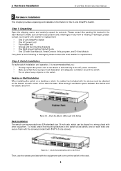
..., attach the mounting brackets to the bottom Rack Installation The switch can be attached on the switch. 2 Hardware Installation D-Link Web Smart Switch User Manual 2 Hardware Installation This chapter provides unpacking and installation information for replacement. Please consult the packing list... Figure 2.1 - Attach the adhesive rubber pads to the switch's side panels (one on each corner of the device's base. One D-Link SmartPro Switch One AC power cord Four rubber feet Screws and two mounting brackets One Multi-lingual Getting Started Guide One CD with the equipment...
..., attach the mounting brackets to the bottom Rack Installation The switch can be attached on the switch. 2 Hardware Installation D-Link Web Smart Switch User Manual 2 Hardware Installation This chapter provides unpacking and installation information for replacement. Please consult the packing list... Figure 2.1 - Attach the adhesive rubber pads to the switch's side panels (one on each corner of the device's base. One D-Link SmartPro Switch One AC power cord Four rubber feet Screws and two mounting brackets One Multi-lingual Getting Started Guide One CD with the equipment...
User Manual
Page 12
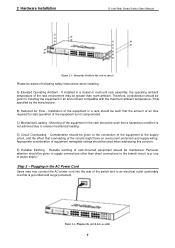
... the rack or chassis Please be aware of rack-mounted equipment should be maintained. Particular attention should be given to the branch circuit (e.g. 2 Hardware Installation D-Link Web Smart Switch User Manual Figure 2.3 - Consideration should be given to the connection of the equipment to the supply circuit, and the effect that the...
... the rack or chassis Please be aware of rack-mounted equipment should be maintained. Particular attention should be given to the branch circuit (e.g. 2 Hardware Installation D-Link Web Smart Switch User Manual Figure 2.3 - Consideration should be given to the connection of the equipment to the supply circuit, and the effect that the...

User Manual
Page 13
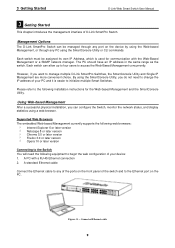
2 Hardware Installation D-Link Web Smart Switch User Manual Power Failure As a precaution, the switch should be unplugged in . 8 When power is resumed, plug the switch back in case of power failure.
2 Hardware Installation D-Link Web Smart Switch User Manual Power Failure As a precaution, the switch should be unplugged in . 8 When power is resumed, plug the switch back in case of power failure.
User Manual
Page 14
...in the same range as the switch. Using Web-based Management After a successful physical installation, you want to manage multiple D-Link SmartPro Switches, the SmartConsole Utility and Single IP Management are more convenient choice. Supported Web Browsers The embedded Web-based Management ...and the SmartConsole Utility. A standard Ethernet cable Connect the Ethernet cable to any PC using a web browser. 3 Getting Started D-Link Web Smart Switch User Manual 3 Getting Started This chapter introduces the management interface of the switch and to the Ethernet port on the...
...in the same range as the switch. Using Web-based Management After a successful physical installation, you want to manage multiple D-Link SmartPro Switches, the SmartConsole Utility and Single IP Management are more convenient choice. Supported Web Browsers The embedded Web-based Management ...and the SmartConsole Utility. A standard Ethernet cable Connect the Ethernet cable to any PC using a web browser. 3 Getting Started D-Link Web Smart Switch User Manual 3 Getting Started This chapter introduces the management interface of the switch and to the Ethernet port on the...
User Manual
Page 15
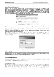
... is 10.90.90.90 with a subnet mask of 255.0.0.0 and a default gateway of 0.0.0.0. one is manual installation. 10 3 Getting Started D-Link Web Smart Switch User Manual Login Web-based Management In order to login and configure the switch via an Ethernet connection, the PC must have...x/y is a number between 0 ~ 254 and z is English. Then press . Please refer to launch the Web-based Management, you through essential settings of the D-Link Web Smart Switch. Logon Dialog Box Smart Wizard After a successful login, the Smart Wizard will guide you may either click the Web Access button at...
... is 10.90.90.90 with a subnet mask of 255.0.0.0 and a default gateway of 0.0.0.0. one is manual installation. 10 3 Getting Started D-Link Web Smart Switch User Manual Login Web-based Management In order to login and configure the switch via an Ethernet connection, the PC must have...x/y is a number between 0 ~ 254 and z is English. Then press . Please refer to launch the Web-based Management, you through essential settings of the D-Link Web Smart Switch. Logon Dialog Box Smart Wizard After a successful login, the Smart Wizard will guide you may either click the Web Access button at...
User Manual
Page 16
...Chapter 4 SmartConsole Utility NOTE: The current SmartConsole Utility does not support IPv6 feature. In the Run dialog box, type D:\D-Link SmartConsole Utility\D-Link_SmartConsole_Utility_v3.00.10.exe (where D:\ represents the drive letter of SmartConsole's functions, please refer to install the SmartConsole...D-Link SmartConsole Utility. 5. Please be sure to install the SmartConsole Utility via the autorun program on the "Install SmartConsole Utility" button and an installation wizard will appear automatically. 3. The autorun program will guide you can discover the DGS-1500 series...
...Chapter 4 SmartConsole Utility NOTE: The current SmartConsole Utility does not support IPv6 feature. In the Run dialog box, type D:\D-Link SmartConsole Utility\D-Link_SmartConsole_Utility_v3.00.10.exe (where D:\ represents the drive letter of SmartConsole's functions, please refer to install the SmartConsole...D-Link SmartConsole Utility. 5. Please be sure to install the SmartConsole Utility via the autorun program on the "Install SmartConsole Utility" button and an installation wizard will appear automatically. 3. The autorun program will guide you can discover the DGS-1500 series...
User Manual
Page 17
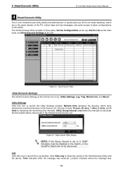
.... Time indicates when the message was received, Location indicates where the message was 12 4 SmartConsole Utility D-Link Web Smart Switch User Manual 4 SmartConsole Utility The D-Link SmartConsole Utility allows the administrator to quickly discover all D-Link smart switches, which were selected as the main body, and SmartConsole Settings at the left . SmartConsole Utility...
.... Time indicates when the message was received, Location indicates where the message was 12 4 SmartConsole Utility D-Link Web Smart Switch User Manual 4 SmartConsole Utility The D-Link SmartConsole Utility allows the administrator to quickly discover all D-Link smart switches, which were selected as the main body, and SmartConsole Settings at the left . SmartConsole Utility...
User Manual
Page 18
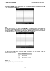
... trap icon in the SmartConsole Settings will see below options: 13 Click Exit to exit Figure 4.4 - Please see below for detailed description. Figure 4.3 - 4 SmartConsole Utility D-Link Web Smart Switch User Manual received and IP Address denotes where it comes from . Click Refresh to redisplay all log entries, click Clear to launch...
... trap icon in the SmartConsole Settings will see below options: 13 Click Exit to exit Figure 4.4 - Please see below for detailed description. Figure 4.3 - 4 SmartConsole Utility D-Link Web Smart Switch User Manual received and IP Address denotes where it comes from . Click Refresh to redisplay all log entries, click Clear to launch...
User Manual
Page 19
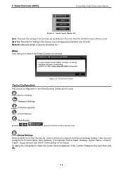
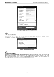
... Confirm Password box and then click OK. 14 Restore: Manually reload a Device List setting file. Device Settings Select a switch from the Device List. 4 SmartConsole Utility D-Link Web Smart Switch User Manual Figure 4.5 - Figure 4.6 - SmartConsole Monitor List Save: Records the setting of the Switch. Here you can configure the Product Name, MAC...
... Confirm Password box and then click OK. 14 Restore: Manually reload a Device List setting file. Device Settings Select a switch from the Device List. 4 SmartConsole Utility D-Link Web Smart Switch User Manual Figure 4.5 - Figure 4.6 - SmartConsole Monitor List Save: Records the setting of the Switch. Here you can configure the Product Name, MAC...
User Manual
Page 20
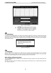
.... Specify the Firmware Path (or Browse for any reason. 15 Input the correct password of the same model name from the Device List. 4 SmartConsole Utility D-Link Web Smart Switch User Manual Figure 4.7 - Click on this icon to use. Click on this icon to launch the Firmware Upgrade window. Here you are...
.... Specify the Firmware Path (or Browse for any reason. 15 Input the correct password of the same model name from the Device List. 4 SmartConsole Utility D-Link Web Smart Switch User Manual Figure 4.7 - Click on this icon to use. Click on this icon to launch the Firmware Upgrade window. Here you are...
User Manual
Page 21
... (eg. button to add a device into the Web-based Management by double-clicking the device in the same domain with the management PC. 4 SmartConsole Utility D-Link Web Smart Switch User Manual Figure 4.9 - Firmware Upgrade CAUTION: Do not disconnect the PC or remove the power cord from the DHCP server. Select that...
... (eg. button to add a device into the Web-based Management by double-clicking the device in the same domain with the management PC. 4 SmartConsole Utility D-Link Web Smart Switch User Manual Figure 4.9 - Firmware Upgrade CAUTION: Do not disconnect the PC or remove the power cord from the DHCP server. Select that...


