Reference Guide
Page 2
... Device Configuration...14 Add(+), Delete(-) and Discover the device 16 Device List...16 5 Configuration ...18 Smart Wizard Configuration...18 IP Information ...18 Password...18 i Table of Contents D-Link Web Smart Switch User Manual Table of Contents Table of Contents ...i About This Guide...1 Terms/Usage...1 Copyright and Trademarks ...1 1 Product Introduction ...2 DGS-1210-20 ...3 Front Panel ...3 Rear Panel...3 DGS-1210-28 ...3 Front Panel ...3 Rear Panel...4 DGS-1210-28P...4 Front Panel ...4 Rear Panel...4 DGS-1210-52 ...5 Front Panel ...5 Rear Panel...5 2 Hardware Installation...
... Device Configuration...14 Add(+), Delete(-) and Discover the device 16 Device List...16 5 Configuration ...18 Smart Wizard Configuration...18 IP Information ...18 Password...18 i Table of Contents D-Link Web Smart Switch User Manual Table of Contents Table of Contents ...i About This Guide...1 Terms/Usage...1 Copyright and Trademarks ...1 1 Product Introduction ...2 DGS-1210-20 ...3 Front Panel ...3 Rear Panel...3 DGS-1210-28 ...3 Front Panel ...3 Rear Panel...4 DGS-1210-28P...4 Front Panel ...4 Rear Panel...4 DGS-1210-52 ...5 Front Panel ...5 Rear Panel...5 2 Hardware Installation...

Reference Guide
Page 3
Table of Contents D-Link Web Smart Switch User Manual SNMP ...19 Web-based Management...21 Tool Bar > Save Menu ...22 Save Configuration ...22 Save Log ...22 Tool Bar > Tool Menu ...22 Reset ...22 Reset System ...22 Reboot Device ...22 Configuration Backup and Restore ...23 Firmware Backup and Upgrade...23 Tool Bar > Smart Wizard...24 Tool Bar > Online Help...24 Function Tree ...26 Device Information...26 System > System Settings ...27 System > Password...27 System > Port Settings...27 System > DHCP Auto Configuration ...28 System > SysLog Host...
Table of Contents D-Link Web Smart Switch User Manual SNMP ...19 Web-based Management...21 Tool Bar > Save Menu ...22 Save Configuration ...22 Save Log ...22 Tool Bar > Tool Menu ...22 Reset ...22 Reset System ...22 Reboot Device ...22 Configuration Backup and Restore ...23 Firmware Backup and Upgrade...23 Tool Bar > Smart Wizard...24 Tool Bar > Online Help...24 Function Tree ...26 Device Information...26 System > System Settings ...27 System > Password...27 System > Port Settings...27 System > DHCP Auto Configuration ...28 System > SysLog Host...
Reference Guide
Page 6
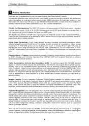
... divided into four parts: 1. About This Guide D-Link Web Smart Switch User Manual About This Guide This guide provides instructions to install the D-Link Gigabit Web Smart Switch DGS-1210-20/28/28P/52, how to use of the device. Microsoft and Windows are commonly accepted for basic switch installation and settings. 3. Refer to terms "switch", "bridge" and "switching hubs" interchangeably, and both are registered trademarks of Microsoft Corporation. Some technologies refer to the Product Instruction and Technical Specification sections for detailed...
... divided into four parts: 1. About This Guide D-Link Web Smart Switch User Manual About This Guide This guide provides instructions to install the D-Link Gigabit Web Smart Switch DGS-1210-20/28/28P/52, how to use of the device. Microsoft and Windows are commonly accepted for basic switch installation and settings. 3. Refer to terms "switch", "bridge" and "switching hubs" interchangeably, and both are registered trademarks of Microsoft Corporation. Some technologies refer to the Product Instruction and Technical Specification sections for detailed...
Reference Guide
Page 7
... or MAC traffic. For PoE model such as shutting down a port, or turning off working hours. Port Security is a powerful tool to the port level. With this utility, users do not need to change or firmware upgrade. Users can help to factory defaults, setting the administrator password, rebooting the Switch, or upgrading the Switch firmware by prioritizing that allows administrators to remotely control their network down per port power off some LED indicators, or adjusting the power usage according to the Ethernet cable connected...
... or MAC traffic. For PoE model such as shutting down a port, or turning off working hours. Port Security is a powerful tool to the port level. With this utility, users do not need to change or firmware upgrade. Users can help to factory defaults, setting the administrator password, rebooting the Switch, or upgrading the Switch firmware by prioritizing that allows administrators to remotely control their network down per port power off some LED indicators, or adjusting the power usage according to the Ethernet cable connected...
Reference Guide
Page 9
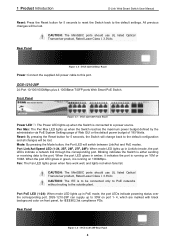
... use UL listed Optical Transceiver product, Rated Laser Class I . 3.3Vdc. Port Link/Act/Speed LED (1-24, 25F, 26F, 27F, 28F): When mode LED lights up in green, it indicates the port is to be lost . Blinking indicates the Switch is running on 10M or 100M. DGS-1210-28P 24-Port 10/100/1000Mbps plus 4 1000Base-T/SFP ports Web Smart PoE Switch. Mode: By pressing the Mode button, the Port LED will be connected only to PoE networks without routing to the default settings. When the port LED...
... use UL listed Optical Transceiver product, Rated Laser Class I . 3.3Vdc. Port Link/Act/Speed LED (1-24, 25F, 26F, 27F, 28F): When mode LED lights up in green, it indicates the port is to be lost . Blinking indicates the Switch is running on 10M or 100M. DGS-1210-28P 24-Port 10/100/1000Mbps plus 4 1000Base-T/SFP ports Web Smart PoE Switch. Mode: By pressing the Mode button, the Port LED will be connected only to PoE networks without routing to the default settings. When the port LED...
Reference Guide
Page 10
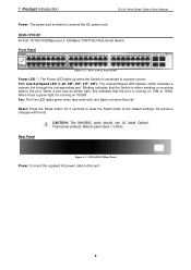
... 4 1000Base-T/SFP Slot Web Smart Switch. All previous changes will be lost. Blinking indicates that the port is either sending or receiving data to the port. CAUTION: The MiniGBIC ports should use UL listed Optical Transceiver product, Rated Laser Class I. 3.3Vdc. Port Link/Act/Speed LED (1-48, 49F, 50F, 51F, 52F): The Link/Act/Speed LED flashes, which indicates a network link through the corresponding port. When a port has an amber light, this port. 5 DGS-1210-52 Rear Panel Power: Connect the supplied AC power cable to this...
... 4 1000Base-T/SFP Slot Web Smart Switch. All previous changes will be lost. Blinking indicates that the port is either sending or receiving data to the port. CAUTION: The MiniGBIC ports should use UL listed Optical Transceiver product, Rated Laser Class I. 3.3Vdc. Port Link/Act/Speed LED (1-48, 49F, 50F, 51F, 52F): The Link/Act/Speed LED flashes, which indicates a network link through the corresponding port. When a port has an amber light, this port. 5 DGS-1210-52 Rear Panel Power: Connect the supplied AC power cable to this...

Reference Guide
Page 14
... 5.0 or later version Safari 4.0 or later version Opera 10 or later version Connecting to initialize multiple Smart Switches. Each switch can configure the Switch, monitor the network status, and display statistics using the SmartConsole Utility, you can allow up to four users to change the IP address of your PC and it is easier to the Switch You will need to access the Web-Based Management concurrently. By using a web browser. Connected Ethernet cable 9 The PC...
... 5.0 or later version Safari 4.0 or later version Opera 10 or later version Connecting to initialize multiple Smart Switches. Each switch can configure the Switch, monitor the network status, and display statistics using the SmartConsole Utility, you can allow up to four users to change the IP address of your PC and it is easier to the Switch You will need to access the Web-Based Management concurrently. By using a web browser. Connected Ethernet cable 9 The PC...

Reference Guide
Page 15
... installation CD is manual installation. 10 3 Getting Started D-Link Web Smart Switch User Manual Login Web-based Management In order to login and configure the switch via an Ethernet connection, the PC must have an IP address of 10.x.y.z (where x/y is a number between 1 ~ 254), and a subnet mask of the Webbased Management interface then click OK. This will enter the Web-based Management interface. Please refer to the Smart Wizard Configuration section for discovering D-Link Smart Switches within the same network segment connected...
... installation CD is manual installation. 10 3 Getting Started D-Link Web Smart Switch User Manual Login Web-based Management In order to login and configure the switch via an Ethernet connection, the PC must have an IP address of 10.x.y.z (where x/y is a number between 1 ~ 254), and a subnet mask of the Webbased Management interface then click OK. This will enter the Web-based Management interface. Please refer to the Smart Wizard Configuration section for discovering D-Link Smart Switches within the same network segment connected...
Reference Guide
Page 28
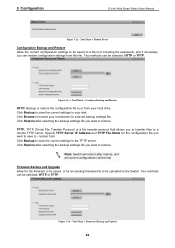
... saved, or for a saved backup settings file. Note: Switch will reboot after restore, and all current configurations will be lost Firmware Backup and Upgrade Allow for the firmware to the Switch. Tool Menu > Firmware Backup and Upload 23 Two methods can be saved to a file (not including the password), and if necessary, you want to save the current settings to restore. Tool Menu > Reboot Device Configuration Backup and Restore Allow the current configuration settings to be selected: HTTP or TFTP. 5 Configuration D-Link Web Smart Switch User Manual...
... saved, or for a saved backup settings file. Note: Switch will reboot after restore, and all current configurations will be lost Firmware Backup and Upgrade Allow for the firmware to the Switch. Tool Menu > Firmware Backup and Upload 23 Two methods can be saved to a file (not including the password), and if necessary, you want to save the current settings to restore. Tool Menu > Reboot Device Configuration Backup and Restore Allow the current configuration settings to be selected: HTTP or TFTP. 5 Configuration D-Link Web Smart Switch User Manual...

Reference Guide
Page 31
... Mirroring: Click Settings to link to AAA > 802.1X > 802.1X Settings. Default is disabled. Default is disabled. Default is enabled. Default is enabled. Device Information 26 Default is disabled. IGMP Snooping: Click Settings to link to System > DHCP Auto Configuration. The following sections provide more detailed description of the switch, including essential information such as firmware & hardware information, and IP address. DHCP Client: Click Settings to link to L2 Functions > Multicast > IGMP Snooping. SNMP Status: Click Settings to link to System > Power Saving...
... Mirroring: Click Settings to link to AAA > 802.1X > 802.1X Settings. Default is disabled. Default is disabled. Default is enabled. Default is enabled. Device Information 26 Default is disabled. IGMP Snooping: Click Settings to link to System > DHCP Auto Configuration. The following sections provide more detailed description of the switch, including essential information such as firmware & hardware information, and IP address. DHCP Client: Click Settings to link to L2 Functions > Multicast > IGMP Snooping. SNMP Status: Click Settings to link to System > Power Saving...

Reference Guide
Page 32
...-login before using the Web-based Management again. If the current session times out (expires), the user is from 120 to take effect. System > Password Access Control System > Port Settings In the Port Setting page, the status of all selected ports by clicking Apply. Login Timeout: The Login Timeout controls the idle time-out period for the changes to 1225 seconds, and 0 means disabling the reporting function. 5 Configuration D-Link Web Smart Switch User Manual System > System Settings The System Setting...
...-login before using the Web-based Management again. If the current session times out (expires), the user is from 120 to take effect. System > Password Access Control System > Port Settings In the Port Setting page, the status of all selected ports by clicking Apply. Login Timeout: The Login Timeout controls the idle time-out period for the changes to 1225 seconds, and 0 means disabling the reporting function. 5 Configuration D-Link Web Smart Switch User Manual System > System Settings The System Setting...

Reference Guide
Page 33
... Mode, or Disabled. When connecting the Switch to detect if the connection is designed on next boot up. Flow Control: You can operate in the DHCP reply packet. 5 Configuration D-Link Web Smart Switch User Manual Figure 5.21 - NOTE: Be sure to other networking devices, a crossover cable must be up properly. Ports configured for users. MDI/MDIX: A medium dependent interface (MDI) port is received from a TFTP server automatically on the switch to other hubs or switches without an Ethernet crossover cable. System > DHCP Auto Configuration...
... Mode, or Disabled. When connecting the Switch to detect if the connection is designed on next boot up. Flow Control: You can operate in the DHCP reply packet. 5 Configuration D-Link Web Smart Switch User Manual Figure 5.21 - NOTE: Be sure to other networking devices, a crossover cable must be up properly. Ports configured for users. MDI/MDIX: A medium dependent interface (MDI) port is received from a TFTP server automatically on the switch to other hubs or switches without an Ethernet crossover cable. System > DHCP Auto Configuration...

Reference Guide
Page 40
... changes of user defined MAC address is 5. The maximum number of Auto Surveillance VLAN global settings. This enables network managers to include all ports into port mirroring. 35 Click Apply to be auto-detected by default. User-defined MAC Settings: Component Type: Auto Surveillance VLAN will auto generate an ACL profile (Profile ID: 56) for all " to better monitor network performances. These five components are Highest, High, Medium and Low. L2 Functions > Jumbo Frame D-Link Gigabit Web Smart Switches support jumbo frames (frames larger than the Ethernet frame size...
... changes of user defined MAC address is 5. The maximum number of Auto Surveillance VLAN global settings. This enables network managers to include all ports into port mirroring. 35 Click Apply to be auto-detected by default. User-defined MAC Settings: Component Type: Auto Surveillance VLAN will auto generate an ACL profile (Profile ID: 56) for all " to better monitor network performances. These five components are Highest, High, Medium and Low. L2 Functions > Jumbo Frame D-Link Gigabit Web Smart Switches support jumbo frames (frames larger than the Ethernet frame size...

Reference Guide
Page 41
... created by a specific port while Spanning Tree Protocol (STP) is not enabled in seconds) for example, connects to include all " to implement changes made. Click "all ports into port mirroring. From Port: The beginning of a consecutive group of learning MAC address automatically, if a port isn't specified as an uplink port (for recovery when a Loopback is Disabled. Click Apply to include all " to a DHCP Server or Gateway). You may be configured starting with the selected port. The Disable Auto...
... created by a specific port while Spanning Tree Protocol (STP) is not enabled in seconds) for example, connects to include all " to implement changes made. Click "all ports into port mirroring. From Port: The beginning of a consecutive group of learning MAC address automatically, if a port isn't specified as an uplink port (for recovery when a Loopback is Disabled. Click Apply to include all " to a DHCP Server or Gateway). You may be configured starting with the selected port. The Disable Auto...

Reference Guide
Page 45
... attached. 40 L2 Functions > Multicast > IGMP Snooping With Internet Group Management Protocol (IGMP) snooping, the Web Smart Switch can help reduce cluttered traffic on the Switch. With IGMP snooping enabled globally, the Web Smart Switch will be configured starting with the selected port. Active LACP ports are two different roles of each frame's Layer 2 MAC header. Timeout: Specify the administrative LACP timeout. Figure 5.42 - Passive - L2 Functions > Link Aggregation > LACP Port Settings The LACP Port Settings is used to create port trunking groups on the LAN...
... attached. 40 L2 Functions > Multicast > IGMP Snooping With Internet Group Management Protocol (IGMP) snooping, the Web Smart Switch can help reduce cluttered traffic on the Switch. With IGMP snooping enabled globally, the Web Smart Switch will be configured starting with the selected port. Active LACP ports are two different roles of each frame's Layer 2 MAC header. Timeout: Specify the administrative LACP timeout. Figure 5.42 - Passive - L2 Functions > Link Aggregation > LACP Port Settings The LACP Port Settings is used to create port trunking groups on the LAN...

Reference Guide
Page 46
... a report message from the multicast group. It also allows adjustments for controlling the frequency of a group. A router port configured manually is a Static Router Port, and a Dynamic Router Port is dynamically configured by each VLAN individually. 5 Configuration D-Link Web Smart Switch User Manual The settings of IGMP snooping is set to zero, and it SHOULD NOT be assigned as router ports for IGMP snooping for the VLAN. Query Interval (60-600 sec): The Query Interval is disabled. Last Member Query Interval...
... a report message from the multicast group. It also allows adjustments for controlling the frequency of a group. A router port configured manually is a Static Router Port, and a Dynamic Router Port is dynamically configured by each VLAN individually. 5 Configuration D-Link Web Smart Switch User Manual The settings of IGMP snooping is set to zero, and it SHOULD NOT be assigned as router ports for IGMP snooping for the VLAN. Query Interval (60-600 sec): The Query Interval is disabled. Last Member Query Interval...

Reference Guide
Page 71
... the IEEE specification. 5 Configuration D-Link Web Smart Switch User Manual Power Used: Displays the current used power of the switch. The percentage of system power supplied: Displays the percentage of system power supplied of the switch. IEEE 802.3at defined that the PSE provides power according to enable the time-based PoE function on designated port(s). Default setting is Enabled. To protect the DGS-1210-28P and the connected devices, the power limit function will display the PoE status including, Port Enable, Power Limit, Power (W), Voltage...
... the IEEE specification. 5 Configuration D-Link Web Smart Switch User Manual Power Used: Displays the current used power of the switch. The percentage of system power supplied: Displays the percentage of system power supplied of the switch. IEEE 802.3at defined that the PSE provides power according to enable the time-based PoE function on designated port(s). Default setting is Enabled. To protect the DGS-1210-28P and the connected devices, the power limit function will display the PoE status including, Port Enable, Power Limit, Power (W), Voltage...

Reference Guide
Page 73
... SNMP agent and used to configure system features for the use of the information controlled by the on the device. The default SNMP global state is 185 watts for DGS-1210-28P). Port Link Up / Link Down: Copper port connection information. PoE Power On / Off: Status of power per port (Only for the last PoE device to be connected to the switch at the same time. 5 Configuration D-Link Web Smart Switch User Manual read and modify the settings of firmware upgrade - Figure 5.89 - PoE...
... SNMP agent and used to configure system features for the use of the information controlled by the on the device. The default SNMP global state is 185 watts for DGS-1210-28P). Port Link Up / Link Down: Copper port connection information. PoE Power On / Off: Status of power per port (Only for the last PoE device to be connected to the switch at the same time. 5 Configuration D-Link Web Smart Switch User Manual read and modify the settings of firmware upgrade - Figure 5.89 - PoE...
Reference Guide
Page 81
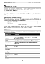
... 2. CLI Commands: The Basic Switch commands in Microsoft Windows, or just use the command prompt by typing the command telnet followed by using the Command Line Interface (CLI) via TELNET: 1. To connect, launch any terminal software like HyperTerminal in the Command Line Interface (CLI) are case-sensitive. To connect a switch via TELNET protocol. Logging on to the Command Line Interface: Enter your User Name and Password to chapter 5. The logon prompt will appear as shown below (DGS-1210-52>): DGS-1210-52 login: admin Password: DGS-1210-52> Figure 6.1 - The command...
... 2. CLI Commands: The Basic Switch commands in Microsoft Windows, or just use the command prompt by typing the command telnet followed by using the Command Line Interface (CLI) via TELNET: 1. To connect, launch any terminal software like HyperTerminal in the Command Line Interface (CLI) are case-sensitive. To connect a switch via TELNET protocol. Logging on to the Command Line Interface: Enter your User Name and Password to chapter 5. The logon prompt will appear as shown below (DGS-1210-52>): DGS-1210-52 login: admin Password: DGS-1210-52> Figure 6.1 - The command...
Reference Guide
Page 92
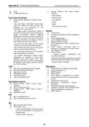
... VLAN Auto-Voice VLAN Auto Surveillance VLAN QoS (Quality of Service) 802.1p priority, DSCP priority queue mapping Up to configure 5 IP addresses for DHCP server. MAC address - ICMP - IGMP - By Port Standby: Each port on /off by default to a single port or multiple ports) - Support manual configuration and scanning for destination IP, system events, fiber port events, twisted-pair port events Password access control Web-based configuration backup / restoration Web-based firmware backup/restore Firmware upgrade using SmartConsole Utility & Web-based management Reset, Reboot ACL...
... VLAN Auto-Voice VLAN Auto Surveillance VLAN QoS (Quality of Service) 802.1p priority, DSCP priority queue mapping Up to configure 5 IP addresses for DHCP server. MAC address - ICMP - IGMP - By Port Standby: Each port on /off by default to a single port or multiple ports) - Support manual configuration and scanning for destination IP, system events, fiber port events, twisted-pair port events Password access control Web-based configuration backup / restoration Web-based firmware backup/restore Firmware upgrade using SmartConsole Utility & Web-based management Reset, Reboot ACL...


