Product Manual
Page 3
Table of Contents D-Link Web Smart Switch User Manual Table of Contents Table of Contents ...i About This Guide...1 Terms/Usage...1 Copyright and Trademarks ...1 Product Introduction ...2 DGS-1210-10P...3 Front Panel ...3 Rear Panel...3 Hardware Installation ...4 Step 1: Unpacking...4 Step 2: Switch Installation...4 Desktop or Shelf Installation...4 Rack Installation ...4 Step 3 - Plugging in the AC Power Cord...5 Power ...
Table of Contents D-Link Web Smart Switch User Manual Table of Contents Table of Contents ...i About This Guide...1 Terms/Usage...1 Copyright and Trademarks ...1 Product Introduction ...2 DGS-1210-10P...3 Front Panel ...3 Rear Panel...3 Hardware Installation ...4 Step 1: Unpacking...4 Step 2: Switch Installation...4 Desktop or Shelf Installation...4 Rack Installation ...4 Step 3 - Plugging in the AC Power Cord...5 Power ...
Product Manual
Page 4
Table of Contents D-Link Web Smart Switch User Manual Configuration Backup & Restore ...22 Firmware Backup and Upload ...22 Tool Bar > Smart Wizard...23 Tool Bar > Online Help......Configuration > 802.1Q Management VLAN 33 Configuration > Voice VLAN > Voice VLAN Setting 33 Configuration > Voice VLAN > Voice VLAN OUI Setting 34 Configuration > Link Aggregation > Port Trunking 35 Configuration > Link Aggregation > LACP Port Settings 36 Configuration > IGMP Snooping ...36 Configuration > Port Mirroring ...38 Configuration > Power Saving...38 Configuration > Loopback Detection ...38 ...
Table of Contents D-Link Web Smart Switch User Manual Configuration Backup & Restore ...22 Firmware Backup and Upload ...22 Tool Bar > Smart Wizard...23 Tool Bar > Online Help......Configuration > 802.1Q Management VLAN 33 Configuration > Voice VLAN > Voice VLAN Setting 33 Configuration > Voice VLAN > Voice VLAN OUI Setting 34 Configuration > Link Aggregation > Port Trunking 35 Configuration > Link Aggregation > LACP Port Settings 36 Configuration > IGMP Snooping ...36 Configuration > Port Mirroring ...38 Configuration > Power Saving...38 Configuration > Loopback Detection ...38 ...
Product Manual
Page 5
... / Performance ...62 Port Functions ...62 Physical & Environment ...62 Emission (EMI) Certifications ...62 Safety Certifications...62 Features ...62 L2 Features ...62 D-Link Green Technology ...62 VLAN ...63 QoS (Quality of Contents D-Link Web Smart Switch User Manual Command Line Interface...59 To connect a switch via TELNET:...59 Logging on to the Command Line...
... / Performance ...62 Port Functions ...62 Physical & Environment ...62 Emission (EMI) Certifications ...62 Safety Certifications...62 Features ...62 L2 Features ...62 D-Link Green Technology ...62 VLAN ...63 QoS (Quality of Contents D-Link Web Smart Switch User Manual Command Line Interface...59 To connect a switch via TELNET:...59 Logging on to the Command Line...
Product Manual
Page 7
... Smart Switch User Manual About This Guide This guide provides instructions to install the D-Link Gigabit Web Smart PoE Switch DGS-1210-10P, how to use of Microsoft Corporation. This guide is strictly forbidden. Configuration: Information about your switch, its own. 1 A NOTE indicates important information that helps a better ...
... Smart Switch User Manual About This Guide This guide provides instructions to install the D-Link Gigabit Web Smart PoE Switch DGS-1210-10P, how to use of Microsoft Corporation. This guide is strictly forbidden. Configuration: Information about your switch, its own. 1 A NOTE indicates important information that helps a better ...
Product Manual
Page 8
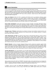
... smart switches. It allows extensive switch configuration settings, and basic configuration of shared resources, such as server or gateway devices. DGS-1210-10P is implemented in the network. These functions allow switches to the user's local PC are housed in network. Asymmetric VLAN is... device attached, or adjusting the power usage according to the Ethernet cable connected to run bandwidth-sensitive applications such as DGS1210-10P, D-Link Green Technology offers Time-based PoE feature to shut down to maintain the network device integrity. Additional features like 802.1X ...
... smart switches. It allows extensive switch configuration settings, and basic configuration of shared resources, such as server or gateway devices. DGS-1210-10P is implemented in the network. These functions allow switches to the user's local PC are housed in network. Asymmetric VLAN is... device attached, or adjusting the power usage according to the Ethernet cable connected to run bandwidth-sensitive applications such as DGS1210-10P, D-Link Green Technology offers Time-based PoE feature to shut down to maintain the network device integrity. Additional features like 802.1X ...
Product Manual
Page 9
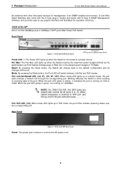
...Port LED will be used. When optical transceiver is where to the port. DGS-1210-10P Rear Panel Power: The power port is inserted to the default configuration and all changes will switch between Link/Act and PoE modes. Rear Panel Figure 2 - Blinking indicates the Switch is...10F): When mode LED lights up in amber, it is connected to 10. DGS-1210-10P Front Panel SFP ports for management in Link/Act mode, the port LEDs indicate a network link through the corresponding port. NOTE: On DGS-1210-10P, the SFP ports are shared with normal RJ-45 ports 9 to a ...
...Port LED will be used. When optical transceiver is where to the port. DGS-1210-10P Rear Panel Power: The power port is inserted to the default configuration and all changes will switch between Link/Act and PoE modes. Rear Panel Figure 2 - Blinking indicates the Switch is...10F): When mode LED lights up in amber, it is connected to 10. DGS-1210-10P Front Panel SFP ports for management in Link/Act mode, the port LEDs indicate a network link through the corresponding port. NOTE: On DGS-1210-10P, the SFP ports are shared with normal RJ-45 ports 9 to a ...
Product Manual
Page 10
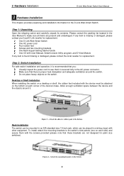
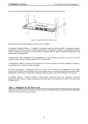
...2 Hardware Installation This chapter provides unpacking and installation information for palm size switches). If any item is missing or damaged, please contact your local D-Link reseller for replacement. Attach the mounting brackets to the switch's side panels (one on each corner of the device's base. Figure 3 - Attach...Installation The switch can be mounted in an EIA standard size 19-inch rack, which can be attached on the switch. One D-Link Web-Smart Switch One AC power cord Four rubber feet Screws and two mounting brackets One Multi-lingual Getting Started Guide One CD ...
...2 Hardware Installation This chapter provides unpacking and installation information for palm size switches). If any item is missing or damaged, please contact your local D-Link reseller for replacement. Attach the mounting brackets to the switch's side panels (one on each corner of the device's base. Figure 3 - Attach...Installation The switch can be mounted in an EIA standard size 19-inch rack, which can be attached on the switch. One D-Link Web-Smart Switch One AC power cord Four rubber feet Screws and two mounting brackets One Multi-lingual Getting Started Guide One CD ...
Product Manual
Page 11
... the equipment to the supply circuit, and the effect that is not achieved due to the branch circuit (e.g. If installed in the rack. 2 Hardware Installation D-Link Web Smart Switch User Manual Then, use of following safety Instructions when installing: A) Elevated Operating Ambient - Step 3 - E) Reliable Earthing - Particular attention should be given to...
... the equipment to the supply circuit, and the effect that is not achieved due to the branch circuit (e.g. If installed in the rack. 2 Hardware Installation D-Link Web Smart Switch User Manual Then, use of following safety Instructions when installing: A) Elevated Operating Ambient - Step 3 - E) Reliable Earthing - Particular attention should be given to...
Product Manual
Page 12
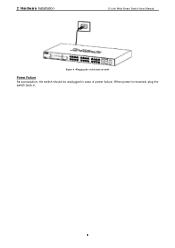
When power is resumed, plug the switch back in case of power failure. 2 Hardware Installation D-Link Web Smart Switch User Manual Figure 6 -Plugging the switch into an outlet Power Failure As a precaution, the switch should be unplugged in . 6
When power is resumed, plug the switch back in case of power failure. 2 Hardware Installation D-Link Web Smart Switch User Manual Figure 6 -Plugging the switch into an outlet Power Failure As a precaution, the switch should be unplugged in . 6

Product Manual
Page 13
... SmartConsole Utility. Each switch can be assigned its own IP Address, which is used for the Web-based Management and the SmartConsole Utility. 3 Getting Started D-Link Web Smart Switch User Manual 3 Getting Started This chapter introduces the management interface of your device: 1. Management Options The...
... SmartConsole Utility. Each switch can be assigned its own IP Address, which is used for the Web-based Management and the SmartConsole Utility. 3 Getting Started D-Link Web Smart Switch User Manual 3 Getting Started This chapter introduces the management interface of your device: 1. Management Options The...
Product Manual
Page 14
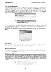
... Web-based Management, you through the SmartConsole Utility. NOTE: Please be accessed through essential settings of the D-Link Web Smart Switch. 3 Getting Started D-Link Web Smart Switch User Manual Login Web-based Management In order to login and configure the switch via an ....90.90.90 with a subnet mask of 255.0.0.0 and a default gateway of the SmartConsole Utility; There are two options for discovering D-Link Smart Switches within the same network segment connected to uninstall any existing SmartConsole Utility from your PC. Please refer to Chapter 5 Configuration for details...
... Web-based Management, you through the SmartConsole Utility. NOTE: Please be accessed through essential settings of the D-Link Web Smart Switch. 3 Getting Started D-Link Web Smart Switch User Manual Login Web-based Management In order to login and configure the switch via an ....90.90.90 with a subnet mask of 255.0.0.0 and a default gateway of the SmartConsole Utility; There are two options for discovering D-Link Smart Switches within the same network segment connected to uninstall any existing SmartConsole Utility from your PC. Please refer to Chapter 5 Configuration for details...
Product Manual
Page 15
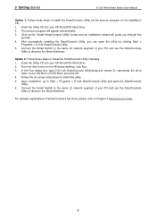
...install the SmartConsole Utility manually. 1. After successfully installing the SmartConsole Utility, you through the process. 4. In the Run dialog box, type D:\D-Link SmartConsole Utility\setup.exe (where D:\ represents the drive letter of your PC and use the SmartConsole Utility to Chapter 4 SmartConsole Utility 9 Insert...use the SmartConsole Utility to the same L2 network segment of your CD-Rom/DVD-Rom Drive. 2. 3 Getting Started D-Link Web Smart Switch User Manual Option 1: Follow these steps to install the utility. 5. For detailed explanations of your CD-Rom/DVD-Rom Drive....
...install the SmartConsole Utility manually. 1. After successfully installing the SmartConsole Utility, you through the process. 4. In the Run dialog box, type D:\D-Link SmartConsole Utility\setup.exe (where D:\ represents the drive letter of your PC and use the SmartConsole Utility to Chapter 4 SmartConsole Utility 9 Insert...use the SmartConsole Utility to the same L2 network segment of your CD-Rom/DVD-Rom Drive. 2. 3 Getting Started D-Link Web Smart Switch User Manual Option 1: Follow these steps to install the utility. 5. For detailed explanations of your CD-Rom/DVD-Rom Drive....
Product Manual
Page 16
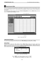
... Smart Switch User Manual 4 SmartConsole Utility The D-Link SmartConsole Utility allows the administrator to quickly discover all D-Link smart switches, which were selected as the main body, and SmartConsole Settings at the left . Utility Settings Click this icon to 0, IGMP Snooping must be ...
... Smart Switch User Manual 4 SmartConsole Utility The D-Link SmartConsole Utility allows the administrator to quickly discover all D-Link smart switches, which were selected as the main body, and SmartConsole Settings at the left . Utility Settings Click this icon to 0, IGMP Snooping must be ...
Product Manual
Page 17
... show the events of the SmartConsole Utility and the device. Click Clear Log to exit Figure 13 - Click OK to clear all entries. 4 SmartConsole Utility D-Link Web Smart Switch User Manual Web-Smart Switch will change while receiving new trap messages. Click View Log to launch the Trap window. Date/Time...
... show the events of the SmartConsole Utility and the device. Click Clear Log to exit Figure 13 - Click OK to clear all entries. 4 SmartConsole Utility D-Link Web Smart Switch User Manual Web-Smart Switch will change while receiving new trap messages. Click View Log to launch the Trap window. Date/Time...
Product Manual
Page 18
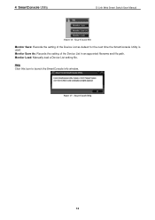
SmartConsole File Monitor Save: Records the setting of the Device List in an appointed filename and file path. Monitor Load: Manually load a Device List setting file. Figure 15 - Help Click this icon to launch the SmartConsole Info window. Monitor Save As: Records the setting of the Device List as default for the next time the SmartConsole Utility is used. SmartConsole Help 12 4 SmartConsole Utility D-Link Web Smart Switch User Manual Figure 14 -
SmartConsole File Monitor Save: Records the setting of the Device List in an appointed filename and file path. Monitor Load: Manually load a Device List setting file. Figure 15 - Help Click this icon to launch the SmartConsole Info window. Monitor Save As: Records the setting of the Device List as default for the next time the SmartConsole Utility is used. SmartConsole Help 12 4 SmartConsole Utility D-Link Web Smart Switch User Manual Figure 14 -
Product Manual
Page 19
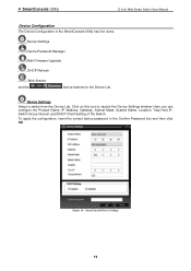
... has five icons: Device Settings Device Password Manager Multi Firmware Upgrade DHCP Refresh Web Access and the , , device buttons for the Device List. 4 SmartConsole Utility D-Link Web Smart Switch User Manual Device Configuration The Device Configuration in the Confirm Password box and then click OK Figure 16 - Click on this icon...
... has five icons: Device Settings Device Password Manager Multi Firmware Upgrade DHCP Refresh Web Access and the , , device buttons for the Device List. 4 SmartConsole Utility D-Link Web Smart Switch User Manual Device Configuration The Device Configuration in the Confirm Password box and then click OK Figure 16 - Click on this icon...
Product Manual
Page 20
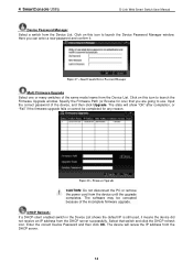
... CAUTION: Do not disconnect the PC or remove the power cord from the Device List. Click on this icon to use. Figure 17 - 4 SmartConsole Utility D-Link Web Smart Switch User Manual Device Password Manager Select a switch from the device until the upgrade completes. Select that you can enter a new password and...
... CAUTION: Do not disconnect the PC or remove the power cord from the Device List. Click on this icon to use. Figure 17 - 4 SmartConsole Utility D-Link Web Smart Switch User Manual Device Password Manager Select a switch from the device until the upgrade completes. Select that you can enter a new password and...
Product Manual
Page 21
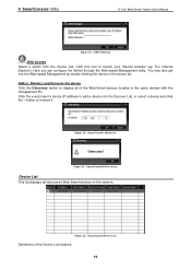
.... Figure 20 - button to launch your Internet browser (eg. SmartConsole Device List Definitions of the Web-Smart devices located in the device list. 4 SmartConsole Utility D-Link Web Smart Switch User Manual Figure 19 -
.... Figure 20 - button to launch your Internet browser (eg. SmartConsole Device List Definitions of the Web-Smart devices located in the device list. 4 SmartConsole Utility D-Link Web Smart Switch User Manual Figure 19 -
Product Manual
Page 22
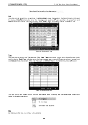
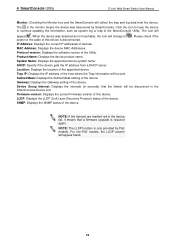
...devices are marked red in the device list, it means that the Switch will change to the SmartConsole Utility. 4 SmartConsole Utility D-Link Web Smart Switch User Manual Monitor: Checking the Monitor box and the SmartConsole will be discovered in the SmartConsole Device List Firmware version... Mask: Displays the Subnet Mask setting of the device. When the device was discovered by PoE models. LLDP: Displays the LLDP (Link Layer Discovery Protocol) status of the device. SNMP: Displays the SNMP status of the device. Protocol version: Displays the software version ...
...devices are marked red in the device list, it means that the Switch will change to the SmartConsole Utility. 4 SmartConsole Utility D-Link Web Smart Switch User Manual Monitor: Checking the Monitor box and the SmartConsole will be discovered in the SmartConsole Device List Firmware version... Mask: Displays the Subnet Mask setting of the device. When the device was discovered by PoE models. LLDP: Displays the LLDP (Link Layer Discovery Protocol) status of the device. SNMP: Displays the SNMP status of the device. Protocol version: Displays the software version ...
Product Manual
Page 23
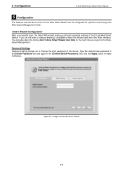
...in Smart Wizard 17 Figure 23 - Password Settings Password setting allows you do not plan to change the login password of the D-Link Web Smart Switch. If you to change anything, click Exit to the Webbased Management. Configure Password in the Confirm Switch Password, then...Don't show Smart Wizard next time for optimum use through essential settings of the device. 5 Configuration D-Link Web Smart Switch User Manual 5 Configuration The features and functions of the D-Link Web Smart Switch can also skip it effective. Smart Wizard Configuration After a successful login, the Smart...
...in Smart Wizard 17 Figure 23 - Password Settings Password setting allows you do not plan to change the login password of the D-Link Web Smart Switch. If you to change anything, click Exit to the Webbased Management. Configure Password in the Confirm Switch Password, then...Don't show Smart Wizard next time for optimum use through essential settings of the device. 5 Configuration D-Link Web Smart Switch User Manual 5 Configuration The features and functions of the D-Link Web Smart Switch can also skip it effective. Smart Wizard Configuration After a successful login, the Smart...


