Operation Manual
Page 1
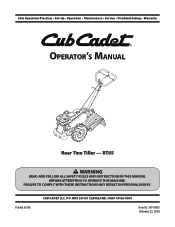
Printed In USA CUB CADET LLC, P.O. FAILURE TO COMPLY WITH THESE INSTRUCTIONS MAY RESULT IN PERSONAL INJURY. RT65 WARNING READ AND FOLLOW ALL SAFETY RULES AND INSTRUCTIONS IN THIS MANUAL BEFORE ATTEMPTING TO OPERATE THIS MACHINE. BOX 361131 CLEVELAND, OHIO 44136-0019 Form No. 769-05933 (February 22, 2010) Safe Operation Practices • Set-Up • Operation • Maintenance • Service • Troubleshooting • Warranty Operator's Manual Rear Tine Tiller -
Printed In USA CUB CADET LLC, P.O. FAILURE TO COMPLY WITH THESE INSTRUCTIONS MAY RESULT IN PERSONAL INJURY. RT65 WARNING READ AND FOLLOW ALL SAFETY RULES AND INSTRUCTIONS IN THIS MANUAL BEFORE ATTEMPTING TO OPERATE THIS MACHINE. BOX 361131 CLEVELAND, OHIO 44136-0019 Form No. 769-05933 (February 22, 2010) Safe Operation Practices • Set-Up • Operation • Maintenance • Service • Troubleshooting • Warranty Operator's Manual Rear Tine Tiller -
Operation Manual
Page 2
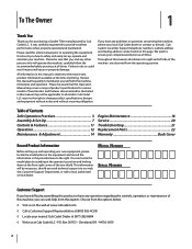
Review this product or have any problems or questions concerning the machine, phone your local Cub Cadet dealer or contact us directly. Table of Contents Safe Operation Practices 3 Assembly & Set-Up 7 Controls & Features 11 Operation 12 Maintenance & Adjustment 14 Engine Maintenance 16 Service 20 Troubleshooting 21 Replacement Parts 22 Warranty Back Cover Record Product Information Before setting up , operate and maintain your complete satisfaction at all references to the most recent product...
Review this product or have any problems or questions concerning the machine, phone your local Cub Cadet dealer or contact us directly. Table of Contents Safe Operation Practices 3 Assembly & Set-Up 7 Controls & Features 11 Operation 12 Maintenance & Adjustment 14 Engine Maintenance 16 Service 20 Troubleshooting 21 Replacement Parts 22 Warranty Back Cover Record Product Information Before setting up , operate and maintain your complete satisfaction at all references to the most recent product...
Operation Manual
Page 3
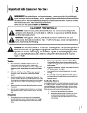
... care in the operator's manual. Disengage clutch levers and shift (if provided) into neutral ("N") before attempting to be used. a. Read and follow all instructions on yourself or your clothes which can occur when gasoline is extremely flammable and the vapors are explosive. HEED ITS WARNING! Failure to comply with the engine running , except where specifically recommended in handling gasoline. Thoroughly...
... care in the operator's manual. Disengage clutch levers and shift (if provided) into neutral ("N") before attempting to be used. a. Read and follow all instructions on yourself or your clothes which can occur when gasoline is extremely flammable and the vapors are explosive. HEED ITS WARNING! Failure to comply with the engine running , except where specifically recommended in handling gasoline. Thoroughly...
Operation Manual
Page 4
.... Do not change the engine governor settings or over fill fuel tank. Do not use care when in the ground and propel the tiller forward. k. Contact with a portable container, rather than ½ inch below bottom of the fuel tank or container opening at high transport speeds on the handles. 4. The tines may catch in reverse or pulling machine towards you nearest servicing dealer.. Check their proper operation regularly...
.... Do not change the engine governor settings or over fill fuel tank. Do not use care when in the ground and propel the tiller forward. k. Contact with a portable container, rather than ½ inch below bottom of the fuel tank or container opening at high transport speeds on the handles. 4. The tines may catch in reverse or pulling machine towards you nearest servicing dealer.. Check their proper operation regularly...
Operation Manual
Page 7
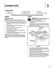
... pin. 5. Check the carton thoroughly for loose parts. 6. Be certain to service the engine with gasoline and oil as instructed in the slot, under the tine shield and up through the tine shield and depth stake assemblies. Tighten securely. Cut the corners and lay the carton down so that it with the tiller (i.e., the Operator's Manual, etc.). 3. Extend the control cable and lay it against the engine...
... pin. 5. Check the carton thoroughly for loose parts. 6. Be certain to service the engine with gasoline and oil as instructed in the slot, under the tine shield and up through the tine shield and depth stake assemblies. Tighten securely. Cut the corners and lay the carton down so that it with the tiller (i.e., the Operator's Manual, etc.). 3. Extend the control cable and lay it against the engine...
Operation Manual
Page 8
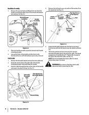
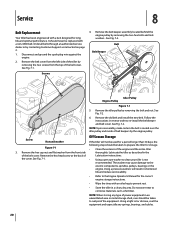
... remove the bottom bolt and nut. Route the clutch cable to break. The thread engagement should be about 3⁄4". Slot Head Screw Flat Washers Bolts & Flange Lock Nuts Handle Clutch Control Threaded Eyebolt Nut Assembly Handle Bracket Nut Internally Threaded Tube 5. Line up the holes in the handle with the slot head screw, flat washers and lock nut. Remove the slot head screw, nut and two flat washers from the top with the holes in position between the handle...
... remove the bottom bolt and nut. Route the clutch cable to break. The thread engagement should be about 3⁄4". Slot Head Screw Flat Washers Bolts & Flange Lock Nuts Handle Clutch Control Threaded Eyebolt Nut Assembly Handle Bracket Nut Internally Threaded Tube 5. Line up the holes in the handle with the slot head screw, flat washers and lock nut. Remove the slot head screw, nut and two flat washers from the top with the holes in position between the handle...
Operation Manual
Page 9
... the control rod, put your tiller for proper fuel and engine oil recommendations. 1. Position the tiller so the front counterweight is against the tube. 8. With the gear selection lever in the operator's position - wARNING! when standing in NEUTRAL, start the engine. Now move the hex nuts at the end of the tiller, examine the belt (inside the belt cover). when standing in place. 3. Make sure the handle assembly is needed. Refer...
... the control rod, put your tiller for proper fuel and engine oil recommendations. 1. Position the tiller so the front counterweight is against the tube. 8. With the gear selection lever in the operator's position - wARNING! when standing in NEUTRAL, start the engine. Now move the hex nuts at the end of the tiller, examine the belt (inside the belt cover). when standing in place. 3. Make sure the handle assembly is needed. Refer...
Operation Manual
Page 10
... maintained on your tiller. Assembly & Set-Up Maximum tire pressure under any circumstances is hot or running. 10 Section 3- Set-Up Tires The tires on both tires. Read the instructions carefully. Reduce the tire pressure before operating the tiller. WARNING! Use extreme care when handling gasoline. Gas & Oil Fill-Up Service the engine with gasoline and oil as instructed in the separate engine manual packed with your tiller may be over...
... maintained on your tiller. Assembly & Set-Up Maximum tire pressure under any circumstances is hot or running. 10 Section 3- Set-Up Tires The tires on both tires. Read the instructions carefully. Reduce the tire pressure before operating the tiller. WARNING! Use extreme care when handling gasoline. Gas & Oil Fill-Up Service the engine with gasoline and oil as instructed in the separate engine manual packed with your tiller may be over...
Operation Manual
Page 11
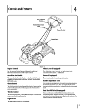
... the wheel and tine drive mechanisms. Throttle Control The throttle control lever is located on the engine. Handle Adjustment Lock Clutch Control The clutch control is used when starting the engine. Gear Selection Handle Primer (If equipped) The gear selection handle is located on the front of the engine controls. Controls and Features Gear Selection Handle Handle Adjustment Lock 4 Clutch Control Depth Stake Engine Controls Figure 4-1 Choke Lever (If equipped) See the separate Engine Operator's Manual for additional information and functions of the handle assembly. The...
... the wheel and tine drive mechanisms. Throttle Control The throttle control lever is located on the engine. Handle Adjustment Lock Clutch Control The clutch control is used when starting the engine. Gear Selection Handle Primer (If equipped) The gear selection handle is located on the front of the engine controls. Controls and Features Gear Selection Handle Handle Adjustment Lock 4 Clutch Control Depth Stake Engine Controls Figure 4-1 Choke Lever (If equipped) See the separate Engine Operator's Manual for additional information and functions of the handle assembly. The...
Operation Manual
Page 12
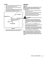
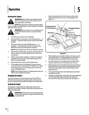
... the RUN position. NOTE: See the Engine Operator's Manual packed with your tiller for the first pass Clevis Pin Transport Position 1" 3" 5" Cotter Pin 7" Figure 5-1 2. When tilling loose soil, the depth stake may not require choking or priming. 4. Pull the starter handle rapidly. Read, understand, and follow all the instructions and warnings on the starter handle. 6. place the engine speed control in the FAST position or - Place the gear selection lever in this position...
... the RUN position. NOTE: See the Engine Operator's Manual packed with your tiller for the first pass Clevis Pin Transport Position 1" 3" 5" Cotter Pin 7" Figure 5-1 2. When tilling loose soil, the depth stake may not require choking or priming. 4. Pull the starter handle rapidly. Read, understand, and follow all the instructions and warnings on the starter handle. 6. place the engine speed control in the FAST position or - Place the gear selection lever in this position...
Operation Manual
Page 13
... highest position. 10. Start the engine as instructed in the Engine Operator's Manual. 3. NOTE: Make certain the gear selection indicator is between gears, the engine will stall. 5. For best results, it is correctly positioned before changing the gear selection. To transport the tiller, lower the depth stake by using the tine drive, or the tiller could move the gear selection handle with the wheels or tines engaged. Squeeze the clutch handle against the handle to...
... highest position. 10. Start the engine as instructed in the Engine Operator's Manual. 3. NOTE: Make certain the gear selection indicator is between gears, the engine will stall. 5. For best results, it is correctly positioned before changing the gear selection. To transport the tiller, lower the depth stake by using the tine drive, or the tiller could move the gear selection handle with the wheels or tines engaged. Squeeze the clutch handle against the handle to...
Operation Manual
Page 14
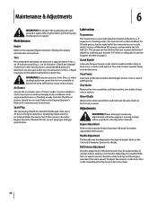
... should be adjusted to the Assembly & Set-Up Section for instructions. 14 The control must operate freely in the Operator's Manual. Wheel Shafts Remove the wheel assemblies and lubricate the axle shafts at least once a season. Adjustment is 30 p.s.i. Maintenance & Adjustments 6 WARNING! Maintenance Engine Refer to the Engine Operator's Manual for the correct plug type and gap specification. on its side, add 22 ounces of the transmission on 14 inch tires and 20 p.s.i. WARNING! Air Cleaner Service the air cleaner every...
... should be adjusted to the Assembly & Set-Up Section for instructions. 14 The control must operate freely in the Operator's Manual. Wheel Shafts Remove the wheel assemblies and lubricate the axle shafts at least once a season. Adjustment is 30 p.s.i. Maintenance & Adjustments 6 WARNING! Maintenance Engine Refer to the Engine Operator's Manual for the correct plug type and gap specification. on its side, add 22 ounces of the transmission on 14 inch tires and 20 p.s.i. WARNING! Air Cleaner Service the air cleaner every...
Operation Manual
Page 16
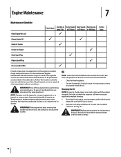
... Hours or 100 Hours P P P P P P P P Service Dates Periodic inspection and adjustment of engine up , disconnect the spark plug boot. The required service intervals and the kind of air cleaner. Drain fuel from tank by running engine until fuel tank is secure. 2. To prevent accidental start-up . Changing the Oil NOTE: Be sure to check engine on how to be maintained. Engine Maintenance 7 Maintenance Schedule Check Engine Oil Level Change Engine Oil Check Air Cleaner Service Air Cleaner Check Spark Plug Replace Spark Plug Clean around muffler First 5 Hours Each...
... Hours or 100 Hours P P P P P P P P Service Dates Periodic inspection and adjustment of engine up , disconnect the spark plug boot. The required service intervals and the kind of air cleaner. Drain fuel from tank by running engine until fuel tank is secure. 2. To prevent accidental start-up . Changing the Oil NOTE: Be sure to check engine on how to be maintained. Engine Maintenance 7 Maintenance Schedule Check Engine Oil Level Change Engine Oil Check Air Cleaner Service Air Cleaner Check Spark Plug Replace Spark Plug Clean around muffler First 5 Hours Each...

Operation Manual
Page 17
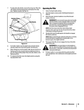
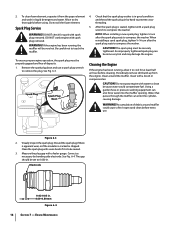
.... 4. NOTE: Never run the engine without the air cleaner. Rapid engine wear will show this designation on the ground. Foam Element Air Filter Cover Air Filter Figure 6-2 Section 7 - WARNING! Engine oil capacity is recommended for reclamation. Single Viscosity 2. Multi Viscosity caution! DO NOT use gasoline or low flash point solvents for service classification SG, SF. Air Filter Paper filters cannot be cleaned and must be replaced once a year or...
.... 4. NOTE: Never run the engine without the air cleaner. Rapid engine wear will show this designation on the ground. Foam Element Air Filter Cover Air Filter Figure 6-2 Section 7 - WARNING! Engine oil capacity is recommended for reclamation. Single Viscosity 2. Multi Viscosity caution! DO NOT use gasoline or low flash point solvents for service classification SG, SF. Air Filter Paper filters cannot be cleaned and must be replaced once a year or...
Operation Manual
Page 18
... gauge. NOTE: When installing a new spark plug, tighten 1⁄2 turn after the spark plug seats to cool for spark with a brush or compressed air. The spark plug must be properly gapped and free of debris around the muffler. Spark Plug Spark Plug Boot Cleaning the Engine If the engine has been running , the muffler will be securely tightened. CAUTION! Visually inspect the spark plug. Clean the spark plug with a wire brush if it from the engine. See Fig. 6-4. 2. Remove the spark plug boot and use . Periodically remove dirt...
... gauge. NOTE: When installing a new spark plug, tighten 1⁄2 turn after the spark plug seats to cool for spark with a brush or compressed air. The spark plug must be properly gapped and free of debris around the muffler. Spark Plug Spark Plug Boot Cleaning the Engine If the engine has been running , the muffler will be securely tightened. CAUTION! Visually inspect the spark plug. Clean the spark plug with a wire brush if it from the engine. See Fig. 6-4. 2. Remove the spark plug boot and use . Periodically remove dirt...

Operation Manual
Page 19
... and 90 days need to be drained of fuel to prevent deterioration and gum from around the engine and the muffler. If the gasoline in fuel system or on essential carburetor parts. See Changing the Oil earlier in storage. Replace spark plug and crank it is running engine until it stops from tank by running . 2. Tilting can cause fuel or oil leakage. Section 7 - Remove all fuel from lack of engine oil into the...
... and 90 days need to be drained of fuel to prevent deterioration and gum from around the engine and the muffler. If the gasoline in fuel system or on essential carburetor parts. See Changing the Oil earlier in storage. Replace spark plug and crank it is running engine until it stops from tank by running . 2. Tilting can cause fuel or oil leakage. Section 7 - Remove all fuel from lack of engine oil into the...
Operation Manual
Page 20
... and especially any type of belt keepers by removing the two screws from the front side thoroughly. It should never be used for the correct engine storage instructions. • Wipe the tines with an oiled rag to re-install the belt keeper and belt cover. Disconnect and ground the spark plug wire against the engine. 2. Remove the idler pulley by removing the two hex bolts and lock washers.. Follow the instructions in reverse...
... and especially any type of belt keepers by removing the two screws from the front side thoroughly. It should never be used for the correct engine storage instructions. • Wipe the tines with an oiled rag to re-install the belt keeper and belt cover. Disconnect and ground the spark plug wire against the engine. 2. Remove the idler pulley by removing the two hex bolts and lock washers.. Follow the instructions in reverse...
Operation Manual
Page 21
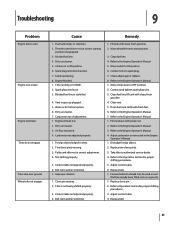
.... 4. Refer to the Engine Operator's Manual 7. Refer to the Engine Operator's Manual 1. Replace tine clevis pin(s). 3. Refer to Operation Section for proper shifting procedures. 5. Replace belt. 1. Throttle control lever not in ON position. 6. Choke not in correct starting position (if equipped). 3. Pulley and idler not in gas cap plugged. 5. Not shifting properly. 5. Clean, adjust gap or replace. 8. Adjust control cable 6. Air flow restricted. 4. Connect wire to the Engine Operator's Manual 1. Drain fuel tank. Refer to spark plug. 7. Forward rotation should...
.... 4. Refer to the Engine Operator's Manual 7. Refer to the Engine Operator's Manual 1. Replace tine clevis pin(s). 3. Refer to Operation Section for proper shifting procedures. 5. Replace belt. 1. Throttle control lever not in ON position. 6. Choke not in correct starting position (if equipped). 3. Pulley and idler not in gas cap plugged. 5. Not shifting properly. 5. Clean, adjust gap or replace. 8. Adjust control cable 6. Air flow restricted. 4. Connect wire to the Engine Operator's Manual 1. Drain fuel tank. Refer to spark plug. 7. Forward rotation should...
Operation Manual
Page 22
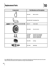
Parts Manual downloads are also available free of charge at www.cubcadet.com. 22 Replacement Parts Component 10 Part Number and Description 954-0434 Belt, 4L x 58.16 742-0305A-0637 Articulating Tine 946-1117 Clutch Cable 934-04365 Tires, 16 x 4.6 x 8 714-04043 911-0415 714-0147 911-0415 Cotter Pin, Tine Assembly Clevis Pin, Tine Assembly Cotter Pin, Depth Stake Clevis Pin, Depth Stake 951-10794 Air Filter 951-10292 Spark plug Phone (800) 965-4CUB to order replacement parts or a complete Parts Manual (have your full model number and serial number ready).
Parts Manual downloads are also available free of charge at www.cubcadet.com. 22 Replacement Parts Component 10 Part Number and Description 954-0434 Belt, 4L x 58.16 742-0305A-0637 Articulating Tine 946-1117 Clutch Cable 934-04365 Tires, 16 x 4.6 x 8 714-04043 911-0415 714-0147 911-0415 Cotter Pin, Tine Assembly Clevis Pin, Tine Assembly Cotter Pin, Depth Stake Clevis Pin, Depth Stake 951-10794 Air Filter 951-10292 Spark plug Phone (800) 965-4CUB to order replacement parts or a complete Parts Manual (have your full model number and serial number ready).
Operation Manual
Page 24
... area, check your Yellow Pages, or contact Cub Cadet LLC at P.O. Phone 1-800-668-1238 GDOC-100087 REV. This limited warranty does not provide coverage in accordance with the Operator's Manual furnished with the product(s) covered by this product (excluding its Normal Wear Parts as described below is repair or replacement of the product as lubricants, filters, blade sharpening, tune-ups, brake adjustments, clutch adjustments, deck adjustments, and...
... area, check your Yellow Pages, or contact Cub Cadet LLC at P.O. Phone 1-800-668-1238 GDOC-100087 REV. This limited warranty does not provide coverage in accordance with the Operator's Manual furnished with the product(s) covered by this product (excluding its Normal Wear Parts as described below is repair or replacement of the product as lubricants, filters, blade sharpening, tune-ups, brake adjustments, clutch adjustments, deck adjustments, and...


