
Hardware Programming Guide
Page 11
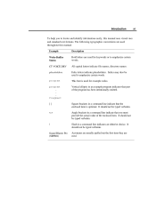
All capital letters indicate file names, directory names. It should not be typed verbatim. Angle brackets in a command line indicate that the enclosed item is used . / Sound Blaster Pro (SBPRO) It should not be used for example codes. Acronyms ... value of the program has been intentionally omitted. Italic letters indicate placeholders. Square brackets in a command line indicate that part of the enclosed item. Vertical ellipsis in a command line indicates an either/or choice. The following typographic conventions are used throughout this manual uses visual cues and...
All capital letters indicate file names, directory names. It should not be typed verbatim. Angle brackets in a command line indicate that the enclosed item is used . / Sound Blaster Pro (SBPRO) It should not be used for example codes. Acronyms ... value of the program has been intentionally omitted. Italic letters indicate placeholders. Square brackets in a command line indicate that part of the enclosed item. Vertical ellipsis in a command line indicates an either/or choice. The following typographic conventions are used throughout this manual uses visual cues and...
Hardware Programming Guide
Page 13
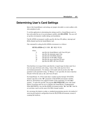
... be the same as follows: SET BLASTER=A220 I5 D1 [H5 M220 P330] where: A I D H M P specifies the Sound Blaster card's base I/O port specifies the interrupt request line specifies the 8-bit DMA channel specifies the 16-bit DMA channel specifies the mixer chip base I/O port specifies the MPU-401 base I/O port Note that...
... be the same as follows: SET BLASTER=A220 I5 D1 [H5 M220 P330] where: A I D H M P specifies the Sound Blaster card's base I/O port specifies the interrupt request line specifies the 8-bit DMA channel specifies the 16-bit DMA channel specifies the mixer chip base I/O port specifies the MPU-401 base I/O port Note that...
Hardware Programming Guide
Page 19
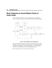
... not as good as that is optional. JOYSTICK PORT MIDI PORT COMMAND/ DATA CT1351 DSP CT1336 BUS INTERFACE CHIP CONTROL AD/DA FILTER AGC MIC LINE IN ISA BUS FM SYNTHESIZER POWER AMP.
... not as good as that is optional. JOYSTICK PORT MIDI PORT COMMAND/ DATA CT1351 DSP CT1336 BUS INTERFACE CHIP CONTROL AD/DA FILTER AGC MIC LINE IN ISA BUS FM SYNTHESIZER POWER AMP.
Hardware Programming Guide
Page 21
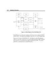
... PORT FILTER COMMAND/ DATA CT1341 DSP CT1336 BUS INTERFACE CHIP CONTROL VOICE DATA AGC CONTROL CT1345 MIXER CHIP CD IN MIC IN ISA BUS CONTROL LINE IN FM SYNTHESIZER POWER AMP CD INTERFACE SPKR CD-ROM DRIVE Figure 1-4: Block Diagram of Sound Blaster Pro. The DSP has been gradually enhanced to...
... PORT FILTER COMMAND/ DATA CT1341 DSP CT1336 BUS INTERFACE CHIP CONTROL VOICE DATA AGC CONTROL CT1345 MIXER CHIP CD IN MIC IN ISA BUS CONTROL LINE IN FM SYNTHESIZER POWER AMP CD INTERFACE SPKR CD-ROM DRIVE Figure 1-4: Block Diagram of Sound Blaster Pro. The DSP has been gradually enhanced to...
Hardware Programming Guide
Page 22
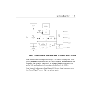
... DATA CT1741 DSP (Mono) CT1745 CT1746 BUS INTERFACE CHIP CT1748 CSP 16-bit AD/DA MIXER CHIP CD IN (Stereo) ISA BUS LINE IN (Stereo) PC-SPKR CONTROL (Mono) LINE-OUT FM SYNTEHSIZER (Stereo) CD INTERFACE WAVE BLASTER POWER AMP SPKR CR-ROM DRIVE Figure 1-5: Block Diagram of the key component is...
... DATA CT1741 DSP (Mono) CT1745 CT1746 BUS INTERFACE CHIP CT1748 CSP 16-bit AD/DA MIXER CHIP CD IN (Stereo) ISA BUS LINE IN (Stereo) PC-SPKR CONTROL (Mono) LINE-OUT FM SYNTEHSIZER (Stereo) CD INTERFACE WAVE BLASTER POWER AMP SPKR CR-ROM DRIVE Figure 1-5: Block Diagram of the key component is...
Hardware Programming Guide
Page 27
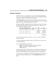
... on "Mixer Chip Programming"). To remain backward compatible, the interrupt acknowledgment of Interrupts With DSP version 4.xx, four interrupts use the same Interrupt Request (IRQ) line. A bit is set to 1 if the corresponding interrupt is not possible to distinguish between 8-bit DMA mode digitized sound I /O and SB-MIDI is thus important...
... on "Mixer Chip Programming"). To remain backward compatible, the interrupt acknowledgment of Interrupts With DSP version 4.xx, four interrupts use the same Interrupt Request (IRQ) line. A bit is set to 1 if the corresponding interrupt is not possible to distinguish between 8-bit DMA mode digitized sound I /O and SB-MIDI is thus important...
Hardware Programming Guide
Page 28
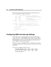
...ChainPreviousISR: ;*** ;*** Chain to previous ISR ExitISR: Configuring DMA and Interrupt Settings With the DSP version 4.xx, the DMA channels Interrupt Request (IRQ) line are accomplished in the same manner as follows: D7 D6 D5 D4 D3 IRQ10 D2 IRQ7 D1 IRQ5 D0 IRQ2 SB16 base I /O instructions ;*** 2).... within a 16-bit DMA mode digitized sound I /O ChainPreviousISR ; The byte from register 80h is used to configure or determine the Interrupt Request line. Mixer data port ; Acknowledge the DSP interrupt; Get interrupt status ; 16-bit DMA-mode digitized sound I /O ISR: mov add mov out...
...ChainPreviousISR: ;*** ;*** Chain to previous ISR ExitISR: Configuring DMA and Interrupt Settings With the DSP version 4.xx, the DMA channels Interrupt Request (IRQ) line are accomplished in the same manner as follows: D7 D6 D5 D4 D3 IRQ10 D2 IRQ7 D1 IRQ5 D0 IRQ2 SB16 base I /O instructions ;*** 2).... within a 16-bit DMA mode digitized sound I /O ChainPreviousISR ; The byte from register 80h is used to configure or determine the Interrupt Request line. Mixer data port ; Acknowledge the DSP interrupt; Get interrupt status ; 16-bit DMA-mode digitized sound I /O ISR: mov add mov out...
Hardware Programming Guide
Page 64
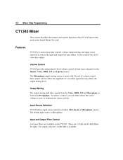
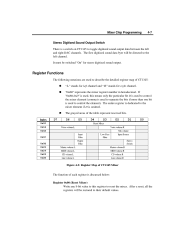
... functions of a recorded signal but only affects the output mixing level. The Microphone output mixing source is available. To silence a source, you can either CD, Line-in sources. Input and Output Filter Control Low-pass filters are 3.2 kHz and 8.8 kHz filters for the Master, Voice, MIDI, CD, and...
... functions of a recorded signal but only affects the output mixing level. The Microphone output mixing source is available. To silence a source, you can either CD, Line-in sources. Input and Output Filter Control Low-pass filters are 3.2 kHz and 8.8 kHz filters for the Master, Voice, MIDI, CD, and...
Hardware Programming Guide
Page 65
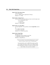
... byte will be restored to reset the mixer. D6 Voice volume.L Input Filter Output Filter Master volume.L MIDI volume.L CD volume.L Line volume.L Master volume.R MIDI volume.R CD volume.R Line volume.R Low-Pass Filter „ Index 0x00 0x04 0x0A 0x0C 0x0E 0x22 0x26 0x28 0x2E D7 D5 D4 D3 D2 Voice volume...
... byte will be restored to reset the mixer. D6 Voice volume.L Input Filter Output Filter Master volume.L MIDI volume.L CD volume.L Line volume.L Master volume.R MIDI volume.R CD volume.R Line volume.R Low-Pass Filter „ Index 0x00 0x04 0x0A 0x0C 0x0E 0x22 0x26 0x28 0x2E D7 D5 D4 D3 D2 Voice volume...
Hardware Programming Guide
Page 66
... low-pass filter. 1 ⇒ Input filter off high-frequency signals during recording to select the input source. 0 or 2 ⇒ Microphone source. 1 ⇒ CD source. 3 ⇒ Line-in approximate 7 dB steps. use the 3.2 kHz filter for mono recording with sampling rates below 18 kHz; 4-8 Mixer Chip Programming Register 0x0A (Mic mixing volume...
... low-pass filter. 1 ⇒ Input filter off high-frequency signals during recording to select the input source. 0 or 2 ⇒ Microphone source. 1 ⇒ CD source. 3 ⇒ Line-in approximate 7 dB steps. use the 3.2 kHz filter for mono recording with sampling rates below 18 kHz; 4-8 Mixer Chip Programming Register 0x0A (Mic mixing volume...
Hardware Programming Guide
Page 67
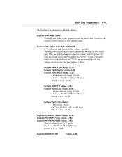
... steps. Default is 0 ⇒ - 46 dB. Turn off , bypass the low-pass filter Default is 0 ⇒ Output filter on. Register 0x28 (CD volume .L/.R) Register 0x2E (Line volume .L/.R) 3 bits per channel, giving 8 levels. 0 to 7 ⇒ - 46 dB to 0 dB, in approximate 4 dB steps. Register 0x0E:5 (Output Filter) Output filter off switch. 0 ⇒...
... steps. Default is 0 ⇒ - 46 dB. Turn off , bypass the low-pass filter Default is 0 ⇒ Output filter on. Register 0x28 (CD volume .L/.R) Register 0x2E (Line volume .L/.R) 3 bits per channel, giving 8 levels. 0 to 7 ⇒ - 46 dB to 0 dB, in approximate 4 dB steps. Register 0x0E:5 (Output Filter) Output filter off switch. 0 ⇒...
Hardware Programming Guide
Page 68
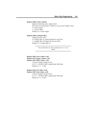
... from terminating the source activity) is also possible to the left channel. Before making a recording, for the Master, Voice, MIDI, CD and Line-In sources. Features The features of CT1745 is that it is to turn the source volume down to CT1345 which only allows single-source recording...mixing path. Volume Control CT1745 provides independent 32-level volume control of the stereo sources to disconnect all four sources from the Mic, CD, Line-In, and MIDI sources concurrently. Output Mixing Control The output mixing path takes signals from CT1345 Mixer. This way, you get left and/or...
... from terminating the source activity) is also possible to the left channel. Before making a recording, for the Master, Voice, MIDI, CD and Line-In sources. Features The features of CT1745 is that it is to turn the source volume down to CT1345 which only allows single-source recording...mixing path. Volume Control CT1745 provides independent 32-level volume control of the stereo sources to disconnect all four sources from the Mic, CD, Line-In, and MIDI sources concurrently. Output Mixing Control The output mixing path takes signals from CT1345 Mixer. This way, you get left and/or...
Hardware Programming Guide
Page 73
..., giving 32 levels. 0 to 31 ⇒ - 62 dB to 0 dB, in 2 dB steps. Default is 12 ⇒ - 12 dB. Register 0x28 (CD volume .L/.R) Register 0x2E (Line volume .L/.R) 4 bits per channel, giving 16 levels. 0 to 15 ⇒ - 60 dB to 0 dB, in place of each register is discussed below: Register 0x00 (Reset...
..., giving 32 levels. 0 to 31 ⇒ - 62 dB to 0 dB, in 2 dB steps. Default is 12 ⇒ - 12 dB. Register 0x28 (CD volume .L/.R) Register 0x2E (Line volume .L/.R) 4 bits per channel, giving 16 levels. 0 to 15 ⇒ - 60 dB to 0 dB, in place of each register is discussed below: Register 0x00 (Reset...
Hardware Programming Guide
Page 74
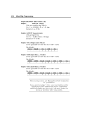
...dB, in 6 dB steps. Default is 0 ⇒ - 62 dB. The default is MIDI.L 0 MIDI.R 0 Line.L 0 Line.R 1 CD.L 0 CD.R 1 Mic 1 When recording in 2 dB steps. 4-16 Mixer Chip Programming Registers 0x38/0x39 (Line volume .L/.R) Register 0x3A (Mic volume) 5 bits per channel, giving 4 levels. 0 to 3 ⇒ - 18 ...input mixer before being sampled. Register 0x3C (Output mixer switches) Set the appropriate bit to 1 to close the switch, 0 to open . The default is Line.L 1 Line.R 1 CD.L 1 CD.R 1 Mic 1 Register 0x3D (Input Mixer.L switches) Set the appropriate bit to 1 to close the switch, 0 to 0...
...dB, in 6 dB steps. Default is 0 ⇒ - 62 dB. The default is MIDI.L 0 MIDI.R 0 Line.L 0 Line.R 1 CD.L 0 CD.R 1 Mic 1 When recording in 2 dB steps. 4-16 Mixer Chip Programming Registers 0x38/0x39 (Line volume .L/.R) Register 0x3A (Mic volume) 5 bits per channel, giving 4 levels. 0 to 3 ⇒ - 18 ...input mixer before being sampled. Register 0x3C (Output mixer switches) Set the appropriate bit to 1 to close the switch, 0 to open . The default is Line.L 1 Line.R 1 CD.L 1 CD.R 1 Mic 1 Register 0x3D (Input Mixer.L switches) Set the appropriate bit to 1 to close the switch, 0 to 0...
Hardware Programming Guide
Page 80
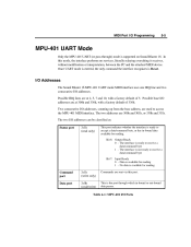
...the port through ) mode is not ready to accept a data/command byte, or has in -bound or out-bound data passes. Possible IRQ lines are sent via this mode, the interface performs no services, literally relaying everything it receives, without modification or interpretation, between the PC and the attached...ready to receive a data/command byte Bit 7: Input Ready 0 - I/O Addresses The Sound Blaster 16 MPU-401 UART mode MIDI interface uses one IRQ line and two consecutive I /O Ports No data is Reset. MIDI Port I/O Programming 5-5 MPU-401 UART Mode Only the MPU-401 UART (or pass-...
...the port through ) mode is not ready to accept a data/command byte, or has in -bound or out-bound data passes. Possible IRQ lines are sent via this mode, the interface performs no services, literally relaying everything it receives, without modification or interpretation, between the PC and the attached...ready to receive a data/command byte Bit 7: Input Ready 0 - I/O Addresses The Sound Blaster 16 MPU-401 UART mode MIDI interface uses one IRQ line and two consecutive I /O Ports No data is Reset. MIDI Port I/O Programming 5-5 MPU-401 UART Mode Only the MPU-401 UART (or pass-...

