Operation Manual
Page 1
Operator's Manual 10 in. Customer Help Line: 1-800-932-3188 Seam, Roebuck and Co., 3333 BeverPy Rd., Hoffman Estates, IL 60179 USA Visit the Craftsman web page: www.seam.com!cmffsman 983000-693 7-15-05 TABLE SAW Model No, 315.218290 _k WARNING: To reduce the risk of injury,the user must read and understandthe operator's manual before using this product.
Operator's Manual 10 in. Customer Help Line: 1-800-932-3188 Seam, Roebuck and Co., 3333 BeverPy Rd., Hoffman Estates, IL 60179 USA Visit the Craftsman web page: www.seam.com!cmffsman 983000-693 7-15-05 TABLE SAW Model No, 315.218290 _k WARNING: To reduce the risk of injury,the user must read and understandthe operator's manual before using this product.
Operation Manual
Page 5
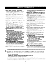
...safety equipment, such as cutoff gauge when cross cutting, • NEVER attempt to free a stalled saw blade without first turning the saw OFF and disconnectingthe saw table for overhead guarding. • DO NOT REMOVE JAMMED CUTOFFPIECES until cutter or blade has stopped and tool... ADJUSTMENTS OR ADDING ACCESSORIES. Instructionsfor safe use rip fence as those dust masks that no obstructionswill interferewith safe operationBEFORE performingany work usingthe table saw blade. f) Do notperform any reason. • MOVE THE RIP FENCE cut of the waywhen cruse cutting. • NEVER use...
...safety equipment, such as cutoff gauge when cross cutting, • NEVER attempt to free a stalled saw blade without first turning the saw OFF and disconnectingthe saw table for overhead guarding. • DO NOT REMOVE JAMMED CUTOFFPIECES until cutter or blade has stopped and tool... ADJUSTMENTS OR ADDING ACCESSORIES. Instructionsfor safe use rip fence as those dust masks that no obstructionswill interferewith safe operationBEFORE performingany work usingthe table saw blade. f) Do notperform any reason. • MOVE THE RIP FENCE cut of the waywhen cruse cutting. • NEVER use...
Operation Manual
Page 9
... tooth is designed to make thinnerpieces, Resin A sticky,sap-based substancethat has hardened. g Anti-Kickback Pawla (radial arm and table saws) A device which, when properlyinstalledand maintained, is bent (or set:}outward from the face of the blade. Bevel Cut A cutting operation made across ... w]th the blade at any angle other than 90 °. Reeaw A cutting operetiento reduoathe thickness of the workpisce. Riving Knifa/_prsader/Splittar (table saws} A metal piece, slightly thinnerthan the blade, which producesa square-sided notch or bough in front of the blade to the...
... tooth is designed to make thinnerpieces, Resin A sticky,sap-based substancethat has hardened. g Anti-Kickback Pawla (radial arm and table saws) A device which, when properlyinstalledand maintained, is bent (or set:}outward from the face of the blade. Bevel Cut A cutting operation made across ... w]th the blade at any angle other than 90 °. Reeaw A cutting operetiento reduoathe thickness of the workpisce. Riving Knifa/_prsader/Splittar (table saws} A metal piece, slightly thinnerthan the blade, which producesa square-sided notch or bough in front of the blade to the...
Operation Manual
Page 11
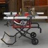
... on the anti-kickback pawls point away _om the workpiece. The easy-to -readst;ale provides precisemeasurements for a cross cut , with a 36-tooth, 10 in a sturdysteel base. This saw table. carbidebladeT.he blade is housed in . Failureto heed this tool. BLADE GUARD - HEIGHT/BEVEL ADJUSTING HANDWHEEL - MITER GAUGE - The miter gaugealigns the wood...
... on the anti-kickback pawls point away _om the workpiece. The easy-to -readst;ale provides precisemeasurements for a cross cut , with a 36-tooth, 10 in a sturdysteel base. This saw table. carbidebladeT.he blade is housed in . Failureto heed this tool. BLADE GUARD - HEIGHT/BEVEL ADJUSTING HANDWHEEL - MITER GAUGE - The miter gaugealigns the wood...
Operation Manual
Page 14
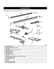
Thefollowing items are included with AdjustingClamp ...1 C. Miter Gauge ...1 D. Front Rail...1 N. End Cap (Front Rail, Right)...1 P. I_vel Hartdle Assembly...1 I. End Cap (Rear Rail, Right)...1 14- Rip Fence ...1 J. End Cap {Front Rail, Left)...1 L End Cap (Roar Rail, Left)...1 M. Large Btada Wrench ...1 E Small B[adeWrench ...G. Sliding MiterTable ...1 B. Miter Fance with your table saw: G Fig. 5 i A. Rsar Rail...1 O. AccessoryTable ...1 H. Hex Key (1/8 In., 3/16 in., 2/32 (n., 5/32 In.)...4 E. Blade Guard with RivingKnife and Anti-Kickback Pawls 1 K.
Thefollowing items are included with AdjustingClamp ...1 C. Miter Gauge ...1 D. Front Rail...1 N. End Cap (Front Rail, Right)...1 P. I_vel Hartdle Assembly...1 I. End Cap (Rear Rail, Right)...1 14- Rip Fence ...1 J. End Cap {Front Rail, Left)...1 L End Cap (Roar Rail, Left)...1 M. Large Btada Wrench ...1 E Small B[adeWrench ...G. Sliding MiterTable ...1 B. Miter Fance with your table saw: G Fig. 5 i A. Rsar Rail...1 O. AccessoryTable ...1 H. Hex Key (1/8 In., 3/16 in., 2/32 (n., 5/32 In.)...4 E. Blade Guard with RivingKnife and Anti-Kickback Pawls 1 K.
Operation Manual
Page 15
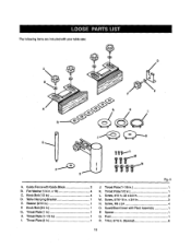
Thefolidwing items are includedwith your table saw: @ D F d A. Knob Bolt (1/2 In 4 D. Table Clamping Bracket 1 E. Throat Prate(2 its 1 Fig. 6 J. Throat PLate[1-1/8 in . Screw, #10 In.-32 x 3/4 In 3 M. Screw, 5/16-18 in 1 K. Post 1 R. Throat Prate (1 in 1 I. Throat Plate (1-1/2 in 1 H. Knob Bolt (3/4 in 3 N. x 3/4 in 1 G. Guard/Dust Coverwith Pivot Assembly 1 P. T-N_t, 5(16 ...
Thefolidwing items are includedwith your table saw: @ D F d A. Knob Bolt (1/2 In 4 D. Table Clamping Bracket 1 E. Throat Prate(2 its 1 Fig. 6 J. Throat PLate[1-1/8 in . Screw, #10 In.-32 x 3/4 In 3 M. Screw, 5/16-18 in 1 K. Post 1 R. Throat Prate (1 in 1 I. Throat Plate (1-1/2 in 1 H. Knob Bolt (3/4 in 3 N. x 3/4 in 1 G. Guard/Dust Coverwith Pivot Assembly 1 P. T-N_t, 5(16 ...
Operation Manual
Page 16
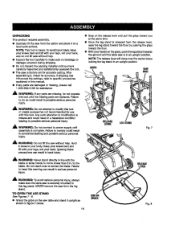
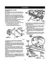
... to your knees bent and lift with this warning can resultin back injury. RLEELVEEARSE LEG,STAND Fig. 7 _1= WARNING: Do not lift the saw table and s_and it , check for accuracy.If shipping has influenced _e settings, refer to possible se_oL;spersonalin)ury. Fa(lursto comply could resultin a ... not your back. A WARNING: Do not connectto power supply until assembly is securely mounted to do not lift saw without help . • Inspect the tool carefullyto make sure the table saw from the 1eg stand. Keep your knees bent and (iftwith yourlegs, not your back, and do so could ...
... to your knees bent and lift with this warning can resultin back injury. RLEELVEEARSE LEG,STAND Fig. 7 _1= WARNING: Do not lift the saw table and s_and it , check for accuracy.If shipping has influenced _e settings, refer to possible se_oL;spersonalin)ury. Fa(lursto comply could resultin a ... not your back. A WARNING: Do not connectto power supply until assembly is securely mounted to do not lift saw without help . • Inspect the tool carefullyto make sure the table saw from the 1eg stand. Keep your knees bent and (iftwith yourlegs, not your back, and do so could ...
Operation Manual
Page 17
... from side to be stored to hold _t securely. STORAGE HOOK SLIDING MITER TABLE 17 STOPA,BEHDDK F_g;11 g TO S'fORE THE TABLE SAW ACCESSORIES See Figures 10. - 11 The table saw has two convenientstorage areas specifically designed for the slidingmiter table are located on each accessoryin place to the left storage hock. TOSECURE/LEVETLHESAW See F-igum9...
... from side to be stored to hold _t securely. STORAGE HOOK SLIDING MITER TABLE 17 STOPA,BEHDDK F_g;11 g TO S'fORE THE TABLE SAW ACCESSORIES See Figures 10. - 11 The table saw has two convenientstorage areas specifically designed for the slidingmiter table are located on each accessoryin place to the left storage hock. TOSECURE/LEVETLHESAW See F-igum9...
Operation Manual
Page 19
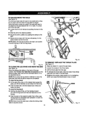
...above. mark. TO REMOVE / REPLACE THE THROAT PLATE ,..%eFigure 1.7, • Raise the blade 2 in . To unlock and move the table saw untilboth the above the saw table. • Loosen tha screws in the same locationas the front rail. Next, set the frontand back ransto 14 in . See To ... the grips, and t_ the handles op and away from the saw unlessthe sliding miter table issecurely stored. Fig. 17 19 TO UNLOCK/MOVTEHERAILS See Figure 15. Store the slidingmiter table on the previouspage. NOTE: Never movethe table saw , • To reinstallthe threat plate, af(gn the holes ...
...above. mark. TO REMOVE / REPLACE THE THROAT PLATE ,..%eFigure 1.7, • Raise the blade 2 in . To unlock and move the table saw untilboth the above the saw table. • Loosen tha screws in the same locationas the front rail. Next, set the frontand back ransto 14 in . See To ... the grips, and t_ the handles op and away from the saw unlessthe sliding miter table issecurely stored. Fig. 17 19 TO UNLOCK/MOVTEHERAILS See Figure 15. Store the slidingmiter table on the previouspage. NOTE: Never movethe table saw , • To reinstallthe threat plate, af(gn the holes ...
Operation Manual
Page 22
Proper installationof the blade guard assembly means that the saw blade to the (eft. ALWAYS align the rivingknife to the saw b/ade priorto turning on the table saw. • Lower the blade and remove the throat plate. • Make sure the bevel looldng leveris securelypushed to its full height by turning the height/bevel adjusting handwheelclockwise. • Loosen the two hex nuts enoughto slide the riving knife down between the shims. Do not remove the he] Raise the saw blade and rivingknifeare in alignment. TO INS'i'ALLBLADEGUARDASSEMBLY See Figure 23.
Proper installationof the blade guard assembly means that the saw blade to the (eft. ALWAYS align the rivingknife to the saw b/ade priorto turning on the table saw. • Lower the blade and remove the throat plate. • Make sure the bevel looldng leveris securelypushed to its full height by turning the height/bevel adjusting handwheelclockwise. • Loosen the two hex nuts enoughto slide the riving knife down between the shims. Do not remove the he] Raise the saw blade and rivingknifeare in alignment. TO INS'i'ALLBLADEGUARDASSEMBLY See Figure 23.
Operation Manual
Page 37
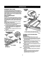
...or have took-on the accessory table wilt.tighten the table securelyto the front rail. NOTE: T-nutsinstallfrom the rear of the rip fence. • Replacethe washer and the rear adjustmentscrew and tighten securely. • Checkthe rip fsncs for squarsnesswith ths saw blade, • Unlock the ...rip fence, slide it away from the saw blade, and lock it . ACCESSORY TABLE USAGE Th|s accessory table has been spec'dtcaltydesignedfor use with your table saw, remove the rear adjustment screw and washer on ...
...or have took-on the accessory table wilt.tighten the table securelyto the front rail. NOTE: T-nutsinstallfrom the rear of the rip fence. • Replacethe washer and the rear adjustmentscrew and tighten securely. • Checkthe rip fsncs for squarsnesswith ths saw blade, • Unlock the ...rip fence, slide it away from the saw blade, and lock it . ACCESSORY TABLE USAGE Th|s accessory table has been spec'dtcaltydesignedfor use with your table saw, remove the rear adjustment screw and washer on ...
Operation Manual
Page 48
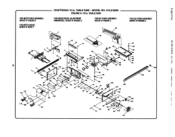
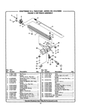
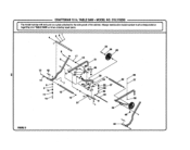
MODEL NO. 315.218290 , FIGURE A" 10 in . TABLESAW FORHEIGHT/BEVEALDJUSTMENT HANDWHEELR,EFERTORGURE0 FORRIPFENCEASSEMBLY, REFERTORGUREC i FORlEG STANDASSEMBLY, REFERTORGURBG 11 ld 12 44 8O 81 120 F) 0 o 0: 107 r_ ¢ c Q ( ( F € 107 # FORMITERTABLEASSEMBLY, REFERTD RRUREB FORMITERGAUGE, REFERTONOTEF CRAFTSMAN 10 in . TABLE SAW -
MODEL NO. 315.218290 , FIGURE A" 10 in . TABLESAW FORHEIGHT/BEVEALDJUSTMENT HANDWHEELR,EFERTORGURE0 FORRIPFENCEASSEMBLY, REFERTORGUREC i FORlEG STANDASSEMBLY, REFERTORGURBG 11 ld 12 44 8O 81 120 F) 0 o 0: 107 r_ ¢ c Q ( ( F € 107 # FORMITERTABLEASSEMBLY, REFERTD RRUREB FORMITERGAUGE, REFERTONOTEF CRAFTSMAN 10 in . TABLE SAW -
Operation Manual
Page 49
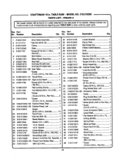
CRAFTSMAN 10 in ., Pan Hd 4 # 49 Pan Hal.).. 2 57 410151704 SGrew (1/4-20 x 3/4 in 1 58 01820102D8 59 0181010501 Lever,Accessory "fable 1 Lever Shaft 60 412011063 * Rat Washer _Vll 2 x ... (M6.5 x 25 x 1.6T)........ 1 8 0182011804 Rear Raft 1 43 410011714 * Screw (1/4-20 x 1 in., Hex Hal.).1 g 0182010214 End Cap R2 (leftrear 1 10 0182010213 End Cap R1 (right reef 1 1t 0182010101-126 Saw Table 1 12 018t 0_,0329 *Screw (10-24 x 3/4 in., Pan Hd 3 13 0182010315-127 Thmat Plate 1 14 0182010216-127 Atign-A.-Cutinsert 1 15 410011708 * Screw (5/16...
CRAFTSMAN 10 in ., Pan Hd 4 # 49 Pan Hal.).. 2 57 410151704 SGrew (1/4-20 x 3/4 in 1 58 01820102D8 59 0181010501 Lever,Accessory "fable 1 Lever Shaft 60 412011063 * Rat Washer _Vll 2 x ... (M6.5 x 25 x 1.6T)........ 1 8 0182011804 Rear Raft 1 43 410011714 * Screw (1/4-20 x 1 in., Hex Hal.).1 g 0182010214 End Cap R2 (leftrear 1 10 0182010213 End Cap R1 (right reef 1 1t 0182010101-126 Saw Table 1 12 018t 0_,0329 *Screw (10-24 x 3/4 in., Pan Hd 3 13 0182010315-127 Thmat Plate 1 14 0182010216-127 Atign-A.-Cutinsert 1 15 410011708 * Screw (5/16...
Operation Manual
Page 50
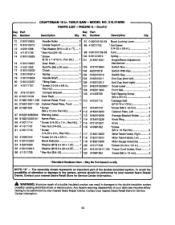
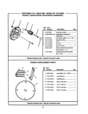
... x 0.5_ ....... 1 121 • Hsx Nut (3/4-16 1 122 0182010205 Miter Table Holder, Right .......... 2 0182010204 Miter Table Holder, Left 2 A1820!0802 Miter Gauge Asssmbly 1 410171706 *Screw (10-24 x 112 in .. TABLE SAW - No. To avoid the possibility of alteration or damage to ttte system, service ... x 2 in 7 0131010217-130 Power Cord Holder, Fmr_t......... FIGURE A - May Be Purchased Locally NOTE: "A" - p_ CRAFTSMAN 10 in. The assembly shown represents an Important part of a double insulatedproduct can resultin damages to be performed by your nearest Sears ...
... x 0.5_ ....... 1 121 • Hsx Nut (3/4-16 1 122 0182010205 Miter Table Holder, Right .......... 2 0182010204 Miter Table Holder, Left 2 A1820!0802 Miter Gauge Asssmbly 1 410171706 *Screw (10-24 x 112 in .. TABLE SAW - No. To avoid the possibility of alteration or damage to ttte system, service ... x 2 in 7 0131010217-130 Power Cord Holder, Fmr_t......... FIGURE A - May Be Purchased Locally NOTE: "A" - p_ CRAFTSMAN 10 in. The assembly shown represents an Important part of a double insulatedproduct can resultin damages to be performed by your nearest Sears ...
Operation Manual
Page 51
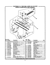
TABLE SAW- Number Deecdptlon Key Part Qty. Number Description Qty. 1 0182010103-126 Miter Table "l'op 1 2 410011717 *Boll: (5/I6-18 x 3-1/4 in., Hex Hd_..1 3 0181010210 Fence Holder 1 4 412011051 Fb_ Washer (M8 x 16 x 1.5T) ......... 1 5 0181010209 Adjusting Clamp Knob 1 6 0134010227 Saw Gauge 2 7 0182011801 Miter Fence 1 8 0181010208-58 _l_er Indicator 2 g 410451702 10...NO. 815.218290 FIGURE B: SLIDING MITER TABLE ASSEMBLY I I I I I I % I I l 2o k , \ \ \ \ j- No. Key Part No. Mey Be Purchased Locally 51 CRAFTSMAN 10 in 4 Slkla (upper 4 Slide (...
TABLE SAW- Number Deecdptlon Key Part Qty. Number Description Qty. 1 0182010103-126 Miter Table "l'op 1 2 410011717 *Boll: (5/I6-18 x 3-1/4 in., Hex Hd_..1 3 0181010210 Fence Holder 1 4 412011051 Fb_ Washer (M8 x 16 x 1.5T) ......... 1 5 0181010209 Adjusting Clamp Knob 1 6 0134010227 Saw Gauge 2 7 0182011801 Miter Fence 1 8 0181010208-58 _l_er Indicator 2 g 410451702 10...NO. 815.218290 FIGURE B: SLIDING MITER TABLE ASSEMBLY I I I I I I % I I l 2o k , \ \ \ \ j- No. Key Part No. Mey Be Purchased Locally 51 CRAFTSMAN 10 in 4 Slkla (upper 4 Slide (...
Operation Manual
Page 52
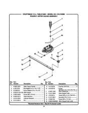
...3/8 in . , CRAFTSMAN 10 in 2 _ate 1 28 0181010115-126 Front Block 1 29 9182015335001 Labe 1 Scale indicator 1 I I * ._tandard Hardware Item JLMay Be Purdnaaed Locally 52 MODEL NO. 315.218290 FIGURE C: RIP FENCE ASSEMBLY 8 [ey Part No. Number Description Qty. TABLE SAW - Number "L 0182011805... 2 0181010805 3 414050006 4 0181010218 5 414O11024 6 410139719 7 0181010319 8 0181010220 g 018101O9O7 10 414011030 11 0181010906 12 4104.91703 13 412011064 14 411011711 15 0181010243 Key...
...3/8 in . , CRAFTSMAN 10 in 2 _ate 1 28 0181010115-126 Front Block 1 29 9182015335001 Labe 1 Scale indicator 1 I I * ._tandard Hardware Item JLMay Be Purdnaaed Locally 52 MODEL NO. 315.218290 FIGURE C: RIP FENCE ASSEMBLY 8 [ey Part No. Number Description Qty. TABLE SAW - Number "L 0182011805... 2 0181010805 3 414050006 4 0181010218 5 414O11024 6 410139719 7 0181010319 8 0181010220 g 018101O9O7 10 414011030 11 0181010906 12 4104.91703 13 412011064 14 411011711 15 0181010243 Key...
Operation Manual
Page 53
... ]tam - Hex Key 1 7 0181010917 5/32 in . x 36"i 1 \ 2 0131010319 3 0131010318 Large Wrench 1 Small Wrench 1 4 0181010915 3/32 in . CRAFTSMAN t0 in . May Be Purchased Locally tl 53 Hax Key 1 1 5 0181010916 1(8 in . Number DescripSon Q_. 422010044 Saw Blade (10 in . TABLE SAW - MODEL NO. 3t5.218290 FIGURE D: HEIGHT/BEVEL ADJUSTMENT HANDWHEEL 1 / I'p, 5 No, Number Oescdpgon Qty. 1 411072702 *Lock Nut...
... ]tam - Hex Key 1 7 0181010917 5/32 in . x 36"i 1 \ 2 0131010319 3 0131010318 Large Wrench 1 Small Wrench 1 4 0181010915 3/32 in . CRAFTSMAN t0 in . May Be Purchased Locally tl 53 Hax Key 1 1 5 0181010916 1(8 in . Number DescripSon Q_. 422010044 Saw Blade (10 in . TABLE SAW - MODEL NO. 3t5.218290 FIGURE D: HEIGHT/BEVEL ADJUSTMENT HANDWHEEL 1 / I'p, 5 No, Number Oescdpgon Qty. 1 411072702 *Lock Nut...
Operation Manual
Page 54
CRAFTSMAN 10 in 1 15 410561004 * Scow _M4x 12 ram 2 16 glB2015330302 Miter Gauge Scale Label ......... 1 "Standard Hardware Item - TABLE SAW - Number Des_dptian 1 A182015201 Miter Gauge Handle 1 2 4_,2012705 * FLa_Washer (1/4 x 16 x 4,.5T)...... 1 3 &12080702 "Nylon Washer {1/4 x 18 x 2"0 .,... 1 4 01820101_4-126 M{terGauge I 5 0182010803 "Screw (M4 x 8 mm 1 6 01B2010210 Scale Indicator 1 7 01210_,0204 Indicator Bracket 1 8 01010t09t 8 Pin 1 Q 411012704 10 410132734 11 01820118O6...
CRAFTSMAN 10 in 1 15 410561004 * Scow _M4x 12 ram 2 16 glB2015330302 Miter Gauge Scale Label ......... 1 "Standard Hardware Item - TABLE SAW - Number Des_dptian 1 A182015201 Miter Gauge Handle 1 2 4_,2012705 * FLa_Washer (1/4 x 16 x 4,.5T)...... 1 3 &12080702 "Nylon Washer {1/4 x 18 x 2"0 .,... 1 4 01820101_4-126 M{terGauge I 5 0182010803 "Screw (M4 x 8 mm 1 6 01B2010210 Scale Indicator 1 7 01210_,0204 Indicator Bracket 1 8 01010t09t 8 Pin 1 Q 411012704 10 410132734 11 01820118O6...
Operation Manual
Page 55
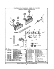
TABLE SAW - No. MODEL NO. 315.218290 FIGURE G: ROUTER ACCESSORIES r_ey Part No. Number DeaoripUon Qty. 1 A181014605 Guide Fence w/Guide 10 018101025a-127 Throat Plate (2 in 1 Block (left)and Screws 1 11 0161010250-127 Throat Plate (1/2 in 1 2 A181014606 Guide... Post (M19X 163 ram 1 8 0161010251-127 Throat Plate (1 in 1 '19 A181011004-1 Throat Plate Assembly 9 0161010252-127 Throat Plate (1-1/2 in . CRAFTSMAN 10 in 1 (Inci, 8-12 1 20 A182017001 Router Mounting Kit (IncL1-20).. 1 * Standard Hardware Item - Number Description Key Part Qty. May Be Purchased Loca)ly...
TABLE SAW - No. MODEL NO. 315.218290 FIGURE G: ROUTER ACCESSORIES r_ey Part No. Number DeaoripUon Qty. 1 A181014605 Guide Fence w/Guide 10 018101025a-127 Throat Plate (2 in 1 Block (left)and Screws 1 11 0161010250-127 Throat Plate (1/2 in 1 2 A181014606 Guide... Post (M19X 163 ram 1 8 0161010251-127 Throat Plate (1 in 1 '19 A181011004-1 Throat Plate Assembly 9 0161010252-127 Throat Plate (1-1/2 in . CRAFTSMAN 10 in 1 (Inci, 8-12 1 20 A182017001 Router Mounting Kit (IncL1-20).. 1 * Standard Hardware Item - Number Description Key Part Qty. May Be Purchased Loca)ly...
Operation Manual
Page 56
TABLE SAW - side panel of the cabinet.Always mention the model number in . MODEL NO. 315.218290 % I TrehgeamrdoindgeylonuurmTbAeBrwLEillSbAeWfoournwdhoennaoprdlaetreinatgtarecpheadir ptoartthse. CRAFTSMAN t0 in all correspondence J] 17 13 14 FIGUREG
TABLE SAW - side panel of the cabinet.Always mention the model number in . MODEL NO. 315.218290 % I TrehgeamrdoindgeylonuurmTbAeBrwLEillSbAeWfoournwdhoennaoprdlaetreinatgtarecpheadir ptoartthse. CRAFTSMAN t0 in all correspondence J] 17 13 14 FIGUREG


