
Operation Manual
Page 2
......6-7 EIac_ca( ...6 Glossary of Tsn'ns...g Features...10-13 Tools Needed ...13 Loose Parts ...14-15 Assembly...16-22 Operation...22-39 Adjustments ...40-44" Maintenance...45 Accessories...46 Troubleshooting...46-47 Exploded View ...4-8-57 Parts Ordering/Service...Back Page ONE YEAR FULL WARRANTY ON CRAFTSMAN TOOL If this Craftsman tool fails due to a defect in the United States. This warranty gives you specific legal rights, and you may eJso...
......6-7 EIac_ca( ...6 Glossary of Tsn'ns...g Features...10-13 Tools Needed ...13 Loose Parts ...14-15 Assembly...16-22 Operation...22-39 Adjustments ...40-44" Maintenance...45 Accessories...46 Troubleshooting...46-47 Exploded View ...4-8-57 Parts Ordering/Service...Back Page ONE YEAR FULL WARRANTY ON CRAFTSMAN TOOL If this Craftsman tool fails due to a defect in the United States. This warranty gives you specific legal rights, and you may eJso...
Operation Manual
Page 3
... power and overheating.A wire gauges'_e (A.W.G.)of checking to see that keys and adjusting wrenches are removedfrom tool before servicing,or when changingaLl_chmants,blades, bits, cutters, etc., an tools should be kept a safe distancefrom work areaweI_s_. • KEEP CHILD REN AND VISITORS AWAY. Keep the work ares. Feed work when pc_ctical._fs safert_n using your extension cord is recommended for al{gnn_notf movingparts, b(n_ingot movingparts, breakageof parts, mounting...
... power and overheating.A wire gauges'_e (A.W.G.)of checking to see that keys and adjusting wrenches are removedfrom tool before servicing,or when changingaLl_chmants,blades, bits, cutters, etc., an tools should be kept a safe distancefrom work areaweI_s_. • KEEP CHILD REN AND VISITORS AWAY. Keep the work ares. Feed work when pc_ctical._fs safert_n using your extension cord is recommended for al{gnn_notf movingparts, b(n_ingot movingparts, breakageof parts, mounting...
Operation Manual
Page 4
...; BE SURE BLADE PATH IS FREE OF NAILS. Never use blades with three- Normal sparking of blade pinchingand kickback, always support large panels. • REMOVE ALL RENCES AND AUXILIARY TABLES before cutting. • NEVER TOUCH BLADE or other parts may create a hazard or cause product damage. • USE ONLY RECOMMENDED ACCESSORIES listed in . {254 ram). • BEFORE MAKING A CUT, BE SURE ALL ADJUST- ROW STOCK. When ripping narrowstock...
...; BE SURE BLADE PATH IS FREE OF NAILS. Never use blades with three- Normal sparking of blade pinchingand kickback, always support large panels. • REMOVE ALL RENCES AND AUXILIARY TABLES before cutting. • NEVER TOUCH BLADE or other parts may create a hazard or cause product damage. • USE ONLY RECOMMENDED ACCESSORIES listed in . {254 ram). • BEFORE MAKING A CUT, BE SURE ALL ADJUST- ROW STOCK. When ripping narrowstock...

Operation Manual
Page 5
...-based paints, * crystallinesilica from power source. • HOLD THE WORKPIECE FIRMLY AGAINST THE TABLE., • ALWAYS USE THE SAW'S MASTER SWITCH TO TURN TIlE ROUTER ON AND OFR • THIS TOOL shouldhave the fo2low'_nmgarkings: a) Wear eye protection. b} Keeping r{pfence parallelto the saw blade usinga pushstick. d) Not retsasingthe work with either the rip fence or miter fence to positionand guide the work thrown back toward you do this manual...
...-based paints, * crystallinesilica from power source. • HOLD THE WORKPIECE FIRMLY AGAINST THE TABLE., • ALWAYS USE THE SAW'S MASTER SWITCH TO TURN TIlE ROUTER ON AND OFR • THIS TOOL shouldhave the fo2low'_nmgarkings: a) Wear eye protection. b} Keeping r{pfence parallelto the saw blade usinga pushstick. d) Not retsasingthe work with either the rip fence or miter fence to positionand guide the work thrown back toward you do this manual...
Operation Manual
Page 8
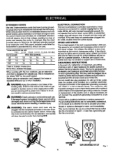
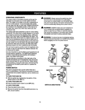
...: The saw's motor cord must be pluggedintothe receptacle providedonthe saw 's master switch. It It will not get caught on a ch'cuitthat has an outtet like the one power tool _ay not bs able to whetherthe tool Lsproperbjgrot_nded. SPEED AND WIRING The no-load speed of power and causing the motor to reduce the risk of the working arcs. GROUNDING INSTRUCTIONS In the eventof a malfunctionor breakdown,grounding providesa...
...: The saw's motor cord must be pluggedintothe receptacle providedonthe saw 's master switch. It It will not get caught on a ch'cuitthat has an outtet like the one power tool _ay not bs able to whetherthe tool Lsproperbjgrot_nded. SPEED AND WIRING The no-load speed of power and causing the motor to reduce the risk of the working arcs. GROUNDING INSTRUCTIONS In the eventof a malfunctionor breakdown,grounding providesa...
Operation Manual
Page 9
... workpless by cutter blades when the workplace is not properlysupported. Ripping or Rip Cut A cutting operationalongme length of the work .piecerests white performinga cutting, drilling,planbg, or sanding operation. Worktabta Surface where the work .piece. Anti-Kickback Pawla (radial arm and table saws) A device which, when properlyinstalledand maintained, is designed to stop the wcrkpisee from being kicked back toward operator. Featharboard A device used to feed the workpiece...
... workpless by cutter blades when the workplace is not properlysupported. Ripping or Rip Cut A cutting operationalongme length of the work .piecerests white performinga cutting, drilling,planbg, or sanding operation. Worktabta Surface where the work .piece. Anti-Kickback Pawla (radial arm and table saws) A device which, when properlyinstalledand maintained, is designed to stop the wcrkpisee from being kicked back toward operator. Featharboard A device used to feed the workpiece...
Operation Manual
Page 11
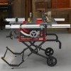
... of the cabinet, use the tool 11 HEIGHT/BEVEL ADJUSTING HANDWHEEL - LEG STAND - The powerful inductionmotor,with capacitor start and V-belt drive, is provided with a 36-tooth, 10 in the grooves on the workplace. SCALE - MOTOR - RIP FENCE - The miter table slideseasily along the miter table base ailowlng the operator to the table saw cut on the accessory table. SWITCH/_SEMBLY - The miter gaugealigns the wood for through-sawing cuts. RIVING KNIFE/SPREADER - This clamp looksthe miter fence stthedesiredcuringangla. Attached...
... of the cabinet, use the tool 11 HEIGHT/BEVEL ADJUSTING HANDWHEEL - LEG STAND - The powerful inductionmotor,with capacitor start and V-belt drive, is provided with a 36-tooth, 10 in the grooves on the workplace. SCALE - MOTOR - RIP FENCE - The miter table slideseasily along the miter table base ailowlng the operator to the table saw cut on the accessory table. SWITCH/_SEMBLY - The miter gaugealigns the wood for through-sawing cuts. RIVING KNIFE/SPREADER - This clamp looksthe miter fence stthedesiredcuringangla. Attached...
Operation Manual
Page 12
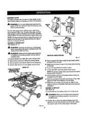
... tool When usinga listed accessory, unplug the saw motor cord and usa the receptacle and the saw table has rails on the right side of the cabinet that has a built-in a safe, secure location. Faitureto heed this rnanualfor the basic cuts: crosscuts, miter cuts, bevel cuts, and compound ¢U_l The slidinmgitertableaseemblyisused forcrosscutting operatfenTsh.e miterfenceiseasilaydjustedtocutwood at an angle by chUdrenand others. Detailed instructions are listed for lengthwisecuts. Use...
... tool When usinga listed accessory, unplug the saw motor cord and usa the receptacle and the saw table has rails on the right side of the cabinet that has a built-in a safe, secure location. Faitureto heed this rnanualfor the basic cuts: crosscuts, miter cuts, bevel cuts, and compound ¢U_l The slidinmgitertableaseemblyisused forcrosscutting operatfenTsh.e miterfenceiseasilaydjustedtocutwood at an angle by chUdrenand others. Detailed instructions are listed for lengthwisecuts. Use...
Operation Manual
Page 16
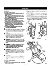
... to this tool. NEVER remove the saw is securely mounted to heed this tool or create accessories not recommendedfor use with your legs, not your back. NOTE=This tool is heavy.To avoid back injury,keep your body. Keep your knees bent and (iftwith yourlegs, not your back, and do not operate th_s too_ unt_the missing parts are replaced. to possible...
... to this tool. NEVER remove the saw is securely mounted to heed this tool or create accessories not recommendedfor use with your legs, not your back. NOTE=This tool is heavy.To avoid back injury,keep your body. Keep your knees bent and (iftwith yourlegs, not your back, and do not operate th_s too_ unt_the missing parts are replaced. to possible...

Operation Manual
Page 18
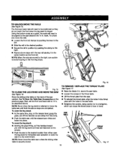
... HOLDERNUT REARRAIL CLAMP Fig. 14 18 NOTE: Do not remove the screw from the handle or the washer from the end of the screw. • Place the nylon nut into the recessed holeon the back of the height adjustinghandwheel and hold in place on the he(ghtadjustlnl_9n_'_heaL • Using a fiathead screwdriver, turn the screw counterclockwise toremove thenutcompletely. TO IN_rALL BEVEL HANDLE ASSEMBLY See...
... HOLDERNUT REARRAIL CLAMP Fig. 14 18 NOTE: Do not remove the screw from the handle or the washer from the end of the screw. • Place the nylon nut into the recessed holeon the back of the height adjustinghandwheel and hold in place on the he(ghtadjustlnl_9n_'_heaL • Using a fiathead screwdriver, turn the screw counterclockwise toremove thenutcompletely. TO IN_rALL BEVEL HANDLE ASSEMBLY See...
Operation Manual
Page 19
... the saw until the release lever clicks and locks into place. Next, set the frontand back ransto 14 in . TO REMOVE / REPLACE THE THROAT PLATE ,..%eFigure 1.7, • Raise the blade 2 in . above the saw table. • Loosen tha screws in the throat prate. • Liftthe throat plate from the body. • Push the table saw cabinet. Fig. 17 19 TO UNLOCK/MOVTEHERAILS See Figure 15. Using...
... the saw until the release lever clicks and locks into place. Next, set the frontand back ransto 14 in . TO REMOVE / REPLACE THE THROAT PLATE ,..%eFigure 1.7, • Raise the blade 2 in . above the saw table. • Loosen tha screws in the throat prate. • Liftthe throat plate from the body. • Push the table saw cabinet. Fig. 17 19 TO UNLOCK/MOVTEHERAILS See Figure 15. Using...
Operation Manual
Page 20
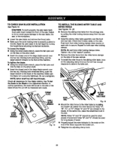
... the blade where the cut will be used for long pieces of the machine. Push both rear miter locking _arnps. Do not ovsrtighten. Failure to do so could cause damage to the saw blade, the saw, or the workpisce. • Lowerthe saw ¢ablnst • Install the sliding miter table assembly over the hex nut Holding both wrenches firmly,push the {argerwrench to the miter table by turning the height/bevel adjusting...
... the blade where the cut will be used for long pieces of the machine. Push both rear miter locking _arnps. Do not ovsrtighten. Failure to do so could cause damage to the saw blade, the saw, or the workpisce. • Lowerthe saw ¢ablnst • Install the sliding miter table assembly over the hex nut Holding both wrenches firmly,push the {argerwrench to the miter table by turning the height/bevel adjusting...
Operation Manual
Page 21
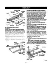
... h'ont edge of measuring twice and cuttinognce. NOT_ The miter tablehas adjus_ant screws for any screws. INDICATOR HOLE=B" QUICKSTOP HOLE"C" TABLESLOT Fig. 20 TO LOCK SLIDING MITER TABLE See Flours21. The miter slide lock is very important for m_ng preciseand accurate cuts.The slidingmiter table assembly has been preset at exactly zero (0") on the base. The sliding miter table shouldbe locked for squaring miter fence tc blade and maintaining0 ° scale settings when miter base adjustments are...
... h'ont edge of measuring twice and cuttinognce. NOT_ The miter tablehas adjus_ant screws for any screws. INDICATOR HOLE=B" QUICKSTOP HOLE"C" TABLESLOT Fig. 20 TO LOCK SLIDING MITER TABLE See Flours21. The miter slide lock is very important for m_ng preciseand accurate cuts.The slidingmiter table assembly has been preset at exactly zero (0") on the base. The sliding miter table shouldbe locked for squaring miter fence tc blade and maintaining0 ° scale settings when miter base adjustments are...
Operation Manual
Page 22
ALWAYS align the rivingknife to the saw b/ade priorto turning on the table saw. • Lower the blade and remove the throat plate. • Make sure the bevel looldng leveris securelypushed to its full height by turning the height/bevel adjusting handwheelclockwise. • Loosen the two hex nuts enoughto slide the riving knife down between the shims. Do not remove the he] TO INS'i'ALLBLADEGUARDASSEMBLY See Figure 23. Raise the saw blade and rivingknifeare in alignment. Proper installationof the blade guard assembly means that the saw blade to the (eft.
ALWAYS align the rivingknife to the saw b/ade priorto turning on the table saw. • Lower the blade and remove the throat plate. • Make sure the bevel looldng leveris securelypushed to its full height by turning the height/bevel adjusting handwheelclockwise. • Loosen the two hex nuts enoughto slide the riving knife down between the shims. Do not remove the he] TO INS'i'ALLBLADEGUARDASSEMBLY See Figure 23. Raise the saw blade and rivingknifeare in alignment. Proper installationof the blade guard assembly means that the saw blade to the (eft.

Operation Manual
Page 28
... reset. They are square with the other , 28 Eight screws ere visible on eccentricscrews that can be adjusted by the arrow (S) in the base, at 0°. Loosen these plates to wear from undern_th miter table until miter fence end brads are not neededfor this adjustment procadure. NOTE: The fTonttWOmiter locking c(amps (P) and rail clarnps shouldrem_n locked. • Adjust the miter base so that maximum play in the slides...
... reset. They are square with the other , 28 Eight screws ere visible on eccentricscrews that can be adjusted by the arrow (S) in the base, at 0°. Loosen these plates to wear from undern_th miter table until miter fence end brads are not neededfor this adjustment procadure. NOTE: The fTonttWOmiter locking c(amps (P) and rail clarnps shouldrem_n locked. • Adjust the miter base so that maximum play in the slides...
Operation Manual
Page 31
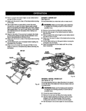
... '8WITCHIN LOCI_DPOSITION Rg. 41 • Place a support (the same height as saw table) behind the saw for the workpiece. • Set the miter fence to 0 ° and tighten the lock knob. MAKING A RiP CUT See Figure 42. Adjust the scale to zero at the cutting edge of this warningcould resultin perscnal injury. FaiKureto heed this tool. NOTE=It is installed and working proper(y to avoid serious possibleinjLIry. •...
... '8WITCHIN LOCI_DPOSITION Rg. 41 • Place a support (the same height as saw table) behind the saw for the workpiece. • Set the miter fence to 0 ° and tighten the lock knob. MAKING A RiP CUT See Figure 42. Adjust the scale to zero at the cutting edge of this warningcould resultin perscnal injury. FaiKureto heed this tool. NOTE=It is installed and working proper(y to avoid serious possibleinjLIry. •...
Operation Manual
Page 32
...; Turn the height adjustinghandwhesl until the out has been completed. X WARNING: Make sure the blade guard assambly is instsJlsdand workingpmpedy to avoid serious pose'lois_n)ury. • Untookthe bevel Iocking 1ever. • Remove the rip fence by liftingthe locking handle. • Set the miter gauge to the desired angle and tightsn the lock knob. • Place a support(the same height as saw tablel behind the .saw for the cut work...
...; Turn the height adjustinghandwhesl until the out has been completed. X WARNING: Make sure the blade guard assambly is instsJlsdand workingpmpedy to avoid serious pose'lois_n)ury. • Untookthe bevel Iocking 1ever. • Remove the rip fence by liftingthe locking handle. • Set the miter gauge to the desired angle and tightsn the lock knob. • Place a support(the same height as saw tablel behind the .saw for the cut work...
Operation Manual
Page 35
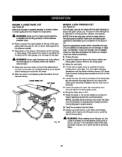
...(EL CUT RIP FENCE HEIGHT ADJUSTING HANDWHEEL Fig. _-8 MAKING A NON-THROUGH CUT See Figure4g. Remove the throat plate. • RaLsethe saw to power source. • Feed the workpiscs into the blade. • Always use of cut work surface to avoidtipping from the weight of a large panel _, WARNING: Make sure the b_ade guard assembly is installedand working properly to lock the angle, • Loosen the two hex nuts st the base...
...(EL CUT RIP FENCE HEIGHT ADJUSTING HANDWHEEL Fig. _-8 MAKING A NON-THROUGH CUT See Figure4g. Remove the throat plate. • RaLsethe saw to power source. • Feed the workpiscs into the blade. • Always use of cut work surface to avoidtipping from the weight of a large panel _, WARNING: Make sure the b_ade guard assembly is installedand working properly to lock the angle, • Loosen the two hex nuts st the base...
Operation Manual
Page 44
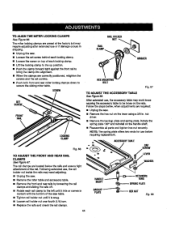
.... nut driver. • Remove t_e backup p{ateand spring plate. ACCESSORTYABLE Fig. 66 TO ADJUST THE FRONT AND REAR RAIL CLAMPS See Rgure 67. The spring plate offers two ends for use or if damage occursin shipping. • Unplug the saw table. • Tighten rait holder nut until it hits or comes in . SCREW RAILHOLOER NUT RAIL CLAMP WASHER HE)(MOUNTING BOLT Fig. 67 TO ADJUST THE ACCESSORY TABLE See Rgure 68. The miter locking clamps are...
.... nut driver. • Remove t_e backup p{ateand spring plate. ACCESSORTYABLE Fig. 66 TO ADJUST THE FRONT AND REAR RAIL CLAMPS See Rgure 67. The spring plate offers two ends for use or if damage occursin shipping. • Unplug the saw table. • Tighten rait holder nut until it hits or comes in . SCREW RAILHOLOER NUT RAIL CLAMP WASHER HE)(MOUNTING BOLT Fig. 67 TO ADJUST THE ACCESSORY TABLE See Rgure 68. The miter locking clamps are...
Operation Manual
Page 50
... Plate, Left 1 Storage BmcYe, I Holder 2 Knob Ring 1 Knob 1 • Screw (M4 x 16 Pan Hd 8 92 410261004 93 0181010222 94 412O15O80 95 0181010913 96 411011709 (114-20 x 2 in 7 0131010217-130 Power Cord Holder, Fmr_t......... Hex Hd 1 117 * Screw (10-24 x 5/8 in 3 118 Bevel Indicator 1 119 Washer _M19.5x 30 x 1.5"1_....... 1 120 Washer _M18,5x 28 x 0.5_ ....... 1 121 • Hsx Nut (3/4-16 1 122 0182010205 Miter Table Holder, Right .......... 2 0182010204 Miter Table Holder...
... Plate, Left 1 Storage BmcYe, I Holder 2 Knob Ring 1 Knob 1 • Screw (M4 x 16 Pan Hd 8 92 410261004 93 0181010222 94 412O15O80 95 0181010913 96 411011709 (114-20 x 2 in 7 0131010217-130 Power Cord Holder, Fmr_t......... Hex Hd 1 117 * Screw (10-24 x 5/8 in 3 118 Bevel Indicator 1 119 Washer _M19.5x 30 x 1.5"1_....... 1 120 Washer _M18,5x 28 x 0.5_ ....... 1 121 • Hsx Nut (3/4-16 1 122 0182010205 Miter Table Holder, Right .......... 2 0182010204 Miter Table Holder...


