Operation Manual
Page 1
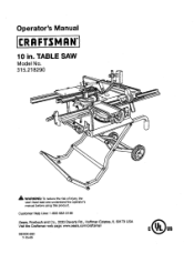
TABLE SAW Model No, 315.218290 _k WARNING: To reduce the risk of injury,the user must read and understandthe operator's manual before using this product. Customer Help Line: 1-800-932-3188 Seam, Roebuck and Co., 3333 BeverPy Rd., Hoffman Estates, IL 60179 USA Visit the Craftsman web page: www.seam.com!cmffsman 983000-693 7-15-05 Operator's Manual 10 in.
TABLE SAW Model No, 315.218290 _k WARNING: To reduce the risk of injury,the user must read and understandthe operator's manual before using this product. Customer Help Line: 1-800-932-3188 Seam, Roebuck and Co., 3333 BeverPy Rd., Hoffman Estates, IL 60179 USA Visit the Craftsman web page: www.seam.com!cmffsman 983000-693 7-15-05 Operator's Manual 10 in.
Operation Manual
Page 4
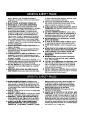
... of blade pinchingand kickback, always support large panels. • REMOVE ALL RENCES AND AUXILIARY TABLES before connecting to remove cut material when blade is tight and not trek(rig contact with saw or workpieca before transpo_ng saw blade. • ALWAYS ,RECURF.WORK firmly against rip fence, miter fence, or miter...BLADE GUARD, RMNG KNIFE/ SPREADEPJSPLrl-rER, AND ANTI-KICKBACK PAWLS on 81[=through the blade instead of accessories that is 10 in this manual or addendums. Use of using your saw blade. Do not rush. • DO NOT USE TOOL IFSWlTCH DOES NOT TURN IT ON AND OFF. If ...
... of blade pinchingand kickback, always support large panels. • REMOVE ALL RENCES AND AUXILIARY TABLES before connecting to remove cut material when blade is tight and not trek(rig contact with saw or workpieca before transpo_ng saw blade. • ALWAYS ,RECURF.WORK firmly against rip fence, miter fence, or miter...BLADE GUARD, RMNG KNIFE/ SPREADEPJSPLrl-rER, AND ANTI-KICKBACK PAWLS on 81[=through the blade instead of accessories that is 10 in this manual or addendums. Use of using your saw blade. Do not rush. • DO NOT USE TOOL IFSWlTCH DOES NOT TURN IT ON AND OFF. If ...
Operation Manual
Page 5
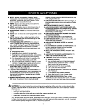
... Do notperform any operationfreehand. d) Not retsasingthe work . I ALWAYS TURN OFF SAW before it can be used, including all through sawing. PLY BEFORE MAKING ADJUSTMENTS OR ADDING ACCESSORIES. If you do this manual or addendums. Use of accessoriesthat are not listed may causethe risk of work before...into the cuttingtool. • USE ONLY RECOMMENDED ACCESSORIES listed in this type of personal in'fury. b} Keeping r{pfence parallelto the saw table for overhead guarding. • DO NOT REMOVE JAMMED CUTOFFPIECES until cutter or blade has stopped and tool has been disconnected from ...
... Do notperform any operationfreehand. d) Not retsasingthe work . I ALWAYS TURN OFF SAW before it can be used, including all through sawing. PLY BEFORE MAKING ADJUSTMENTS OR ADDING ACCESSORIES. If you do this manual or addendums. Use of accessoriesthat are not listed may causethe risk of work before...into the cuttingtool. • USE ONLY RECOMMENDED ACCESSORIES listed in this type of personal in'fury. b} Keeping r{pfence parallelto the saw table for overhead guarding. • DO NOT REMOVE JAMMED CUTOFFPIECES until cutter or blade has stopped and tool has been disconnected from ...
Operation Manual
Page 16
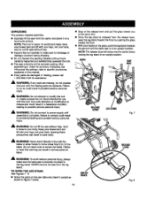
... set far accurate cutt'_ng.After assembling it upright as shown in figure 7 be(ow. 16 cENTER BRACE Fig, 8 to specificprocedures expta'medin _is manual. • If any parts are damaged or missing, plasea call 1-800-932-3188 for accuracy.If shipping has influenced _e settings, refer to the ....To avoid back injury,keep your knees bent and lift with your legs, not your back, and do not lift saw without help . • Inspect the tool carefullyto make sure the table saw without help . NOTE: The release leverwill close to this leg stand. A WARNING: Do not connectto power supply until ...
... set far accurate cutt'_ng.After assembling it upright as shown in figure 7 be(ow. 16 cENTER BRACE Fig, 8 to specificprocedures expta'medin _is manual. • If any parts are damaged or missing, plasea call 1-800-932-3188 for accuracy.If shipping has influenced _e settings, refer to the ....To avoid back injury,keep your knees bent and lift with your legs, not your back, and do not lift saw without help . • Inspect the tool carefullyto make sure the table saw without help . NOTE: The release leverwill close to this leg stand. A WARNING: Do not connectto power supply until ...
Operation Manual
Page 22
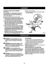
TO INS'i'ALLBLADEGUARDASSEMBLY See Figure 23. ALWAYS align the rivingknife to the saw b/ade priorto turning on the table saw blade to the (eft. Raise the saw . • Lower the blade and remove the throat plate. • Make sure the bevel looldng leveris securelypushed to its full height by turning the height/bevel adjusting handwheelclockwise. • Loosen the two hex nuts enoughto slide the riving knife down between the shims. Do not remove the he] Proper installationof the blade guard assembly means that the saw blade and rivingknifeare in alignment.
TO INS'i'ALLBLADEGUARDASSEMBLY See Figure 23. ALWAYS align the rivingknife to the saw b/ade priorto turning on the table saw blade to the (eft. Raise the saw . • Lower the blade and remove the throat plate. • Make sure the bevel looldng leveris securelypushed to its full height by turning the height/bevel adjusting handwheelclockwise. • Loosen the two hex nuts enoughto slide the riving knife down between the shims. Do not remove the he] Proper installationof the blade guard assembly means that the saw blade and rivingknifeare in alignment.
Operation Manual
Page 30
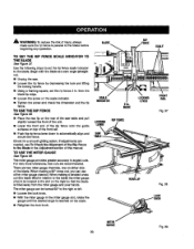
... test cuts are two miter gauge channels, one on either miter gauge channel. When maldng a 90 ° cross cut (the blade tilted in relationto the table) the miter gauge sheutd be turned 60 ° to the b_ade before b_innfng any opar_t'_o_. MARl( LOCKING LEVER RA]L Fig. 37 LOCKING RiP FENCE... rip fence 2 in the Adjusfrnenfsection of the rip fence onto the guide surfaces on the rear of the saw table and pull slighttytoward the front of the unit. • Lower the front end of this manual. & WARNING: "1"roeduce the r_k of injury, always make sure the rip fence is reached on the ...
... test cuts are two miter gauge channels, one on either miter gauge channel. When maldng a 90 ° cross cut (the blade tilted in relationto the table) the miter gauge sheutd be turned 60 ° to the b_ade before b_innfng any opar_t'_o_. MARl( LOCKING LEVER RA]L Fig. 37 LOCKING RiP FENCE... rip fence 2 in the Adjusfrnenfsection of the rip fence onto the guide surfaces on the rear of the saw table and pull slighttytoward the front of the unit. • Lower the front end of this manual. & WARNING: "1"roeduce the r_k of injury, always make sure the rip fence is reached on the ...
Operation Manual
Page 57
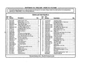
Number DescdpUon PARTS LIST FOR FIGURE G Key Part Qty. May Be Purchased LoP.ally CRAFTSMAN 10 in 2 36 410151714 * Sooket Hex Head Screw (1/4x 40 rnm 4 37 412011003 * Washer... Screw (M6 x 15 ram 1 Nylon Nut 1 A132011301 Leg Stand Assembly (Inol.1-49 1 983000693 Operator's Manual * Standard Hardware Item - TABLE SAW - MODEL NO. 315.218290 l rehgeamrdoindgelynoumrTbAeBrwLEillSbAeWfouonrdwhoenneoprdlaetreinatgtareophaeidr ptoartthse. No, Number Description 1 4101717O6 • Screw {10-24x 1/2 2 2 412011020 * Washer (M5.2 x 14 x 1T 2 3 016101O201 Feet Plug (M34 ...
Number DescdpUon PARTS LIST FOR FIGURE G Key Part Qty. May Be Purchased LoP.ally CRAFTSMAN 10 in 2 36 410151714 * Sooket Hex Head Screw (1/4x 40 rnm 4 37 412011003 * Washer... Screw (M6 x 15 ram 1 Nylon Nut 1 A132011301 Leg Stand Assembly (Inol.1-49 1 983000693 Operator's Manual * Standard Hardware Item - TABLE SAW - MODEL NO. 315.218290 l rehgeamrdoindgelynoumrTbAeBrwLEillSbAeWfouonrdwhoenneoprdlaetreinatgtareophaeidr ptoartthse. No, Number Description 1 4101717O6 • Screw {10-24x 1/2 2 2 412011020 * Washer (M5.2 x 14 x 1T 2 3 016101O201 Feet Plug (M34 ...


