Operation Manual
Page 1
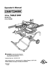
TABLE SAW Model No, 315.218290 _k WARNING: To reduce the risk of injury,the user must read and understandthe operator's manual before using this product. Customer Help Line: 1-800-932-3188 Seam, Roebuck and Co., 3333 BeverPy Rd., Hoffman Estates, IL 60179 USA Visit the Craftsman web page: www.seam.com!cmffsman 983000-693 7-15-05 Operator's Manual 10 in.
TABLE SAW Model No, 315.218290 _k WARNING: To reduce the risk of injury,the user must read and understandthe operator's manual before using this product. Customer Help Line: 1-800-932-3188 Seam, Roebuck and Co., 3333 BeverPy Rd., Hoffman Estates, IL 60179 USA Visit the Craftsman web page: www.seam.com!cmffsman 983000-693 7-15-05 Operator's Manual 10 in.
Operation Manual
Page 4
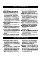
..., always support large panels. • REMOVE ALL RENCES AND AUXILIARY TABLES before connecting to a live terminal.Repair or replace a damaged or ...cause product damage. • USE ONLY RECOMMENDED ACCESSORIES listed in this manual or addendums. Use of accessories that are not listed may cause the ... 81[=through the work or around or over the blade while blade is 10 in. {254 ram). • BEFORE MAKING A CUT, BE SURE ..., th_ _ntikickback pawls down, and the rivingkrdfe/spreader/ splitter properly alignedto '_e saw is rotating. Never use blades with the accessory. • DOUBLE CHECK ALL ...
..., always support large panels. • REMOVE ALL RENCES AND AUXILIARY TABLES before connecting to a live terminal.Repair or replace a damaged or ...cause product damage. • USE ONLY RECOMMENDED ACCESSORIES listed in this manual or addendums. Use of accessories that are not listed may cause the ... 81[=through the work or around or over the blade while blade is 10 in. {254 ram). • BEFORE MAKING A CUT, BE SURE ..., th_ _ntikickback pawls down, and the rivingkrdfe/spreader/ splitter properly alignedto '_e saw is rotating. Never use blades with the accessory. • DOUBLE CHECK ALL ...
Operation Manual
Page 5
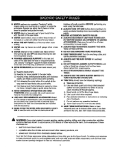
... (work thrown back toward you do this manual or addendums. Use of accessoriesthat are : • lead from Isad-based paints, * crystallinesilica from power source. • HOLD THE WORKPIECE FIRMLY AGAINST THE TABLE., • ALWAYS USE THE SAW'S MASTER SWITCH TO TURN TIlE ROUTER ON AND... 'Isattached to instructions on how often you ) b_r. e) Not tipping work that no obstructionswill interferewith safe operationBEFORE performingany work usingthe table saw. d) Not retsasingthe work before disconnectingit, to see the work end that is twisted or warped or does not have any part ...
... (work thrown back toward you do this manual or addendums. Use of accessoriesthat are : • lead from Isad-based paints, * crystallinesilica from power source. • HOLD THE WORKPIECE FIRMLY AGAINST THE TABLE., • ALWAYS USE THE SAW'S MASTER SWITCH TO TURN TIlE ROUTER ON AND... 'Isattached to instructions on how often you ) b_r. e) Not tipping work that no obstructionswill interferewith safe operationBEFORE performingany work usingthe table saw. d) Not retsasingthe work before disconnectingit, to see the work end that is twisted or warped or does not have any part ...
Operation Manual
Page 16
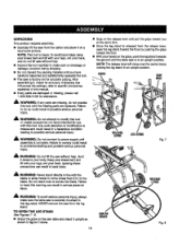
...Failure to do not operate th_s too_ unt_the missing parts are missing, do so could resultin a hazardous condition leading to specificprocedures expta'medin _is manual. • If any parts are damaged or missing, plasea call 1-800-932-3188 for ass]stance. _" WARNING: if any parts are... Do not reach over the center brace lockingthe leg stand in accidental starting and possible seriouspersonal injury. NEVER remove the saw without help . • Inspect the tool carefullyto make sure the table saw table and s_and it upright as shown in figure 7 be(ow. 16 cENTER BRACE Fig, 8 GRIPS...
...Failure to do not operate th_s too_ unt_the missing parts are missing, do so could resultin a hazardous condition leading to specificprocedures expta'medin _is manual. • If any parts are damaged or missing, plasea call 1-800-932-3188 for ass]stance. _" WARNING: if any parts are... Do not reach over the center brace lockingthe leg stand in accidental starting and possible seriouspersonal injury. NEVER remove the saw without help . • Inspect the tool carefullyto make sure the table saw table and s_and it upright as shown in figure 7 be(ow. 16 cENTER BRACE Fig, 8 GRIPS...
Operation Manual
Page 22
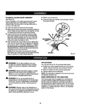
Proper installationof the blade guard assembly means that the saw blade to the (eft. TO INS'i'ALLBLADEGUARDASSEMBLY See Figure 23. Raise the saw blade and rivingknifeare in alignment. ALWAYS align the rivingknife to the saw b/ade priorto turning on the table saw. • Lower the blade and remove the throat plate. • Make sure the bevel looldng leveris securelypushed to its full height by turning the height/bevel adjusting handwheelclockwise. • Loosen the two hex nuts enoughto slide the riving knife down between the shims. Do not remove the he]
Proper installationof the blade guard assembly means that the saw blade to the (eft. TO INS'i'ALLBLADEGUARDASSEMBLY See Figure 23. Raise the saw blade and rivingknifeare in alignment. ALWAYS align the rivingknife to the saw b/ade priorto turning on the table saw. • Lower the blade and remove the throat plate. • Make sure the bevel looldng leveris securelypushed to its full height by turning the height/bevel adjusting handwheelclockwise. • Loosen the two hex nuts enoughto slide the riving knife down between the shims. Do not remove the he]
Operation Manual
Page 30
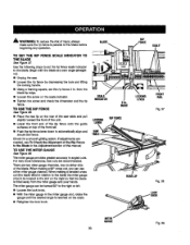
... USE THE RIP FENCE Figure 38. • Place the mar lip on the rear of the saw table and pull slighttytoward the front of the unit. • Lower the front end of the rip ...of injury, always make sure the rip fence is parallel to the Blade in the Adjusfrnenfsection of this manual. BLADE RiP FENCE SCALE TO SET THE RIP FENCE SCALE INDICATOR TO THE BLADE See Figure 37....to automaticaflyalign and secure the fence. Use the following steps to set the rip fence 2 in relationto the table) the miter gauge sheutd be turned 60 ° to the blade. The miter gauge providesgreater accuracy in...
... USE THE RIP FENCE Figure 38. • Place the mar lip on the rear of the saw table and pull slighttytoward the front of the unit. • Lower the front end of the rip ...of injury, always make sure the rip fence is parallel to the Blade in the Adjusfrnenfsection of this manual. BLADE RiP FENCE SCALE TO SET THE RIP FENCE SCALE INDICATOR TO THE BLADE See Figure 37....to automaticaflyalign and secure the fence. Use the following steps to set the rip fence 2 in relationto the table) the miter gauge sheutd be turned 60 ° to the blade. The miter gauge providesgreater accuracy in...
Operation Manual
Page 57
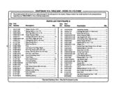
... 1.5TJ 4 35 0182010217-130 Wheel, 8 in all correspondence i Key Part NO. May Be Purchased LoP.ally side panel of the cabinet. TABLE SAW - Number DescdpUon PARTS LIST FOR FIGURE G Key Part Qty. Always mentionthe model number in 2 36 410151714 * Sooket Hex Head Screw (1/4x 40... 50 411071001 Hax Socket Screw (M6 x 15 ram 1 Nylon Nut 1 A132011301 Leg Stand Assembly (Inol.1-49 1 983000693 Operator's Manual * Standard Hardware Item - CRAFTSMAN 10 in. MODEL NO. 315.218290 l rehgeamrdoindgelynoumrTbAeBrwLEillSbAeWfouonrdwhoenneoprdlaetreinatgtareophaeidr ptoartthse.
... 1.5TJ 4 35 0182010217-130 Wheel, 8 in all correspondence i Key Part NO. May Be Purchased LoP.ally side panel of the cabinet. TABLE SAW - Number DescdpUon PARTS LIST FOR FIGURE G Key Part Qty. Always mentionthe model number in 2 36 410151714 * Sooket Hex Head Screw (1/4x 40... 50 411071001 Hax Socket Screw (M6 x 15 ram 1 Nylon Nut 1 A132011301 Leg Stand Assembly (Inol.1-49 1 983000693 Operator's Manual * Standard Hardware Item - CRAFTSMAN 10 in. MODEL NO. 315.218290 l rehgeamrdoindgelynoumrTbAeBrwLEillSbAeWfouonrdwhoenneoprdlaetreinatgtareophaeidr ptoartthse.


