
Operation Manual
Page 1
Operator's Manual CRRFISMRN ° 4 x 36" Belt 6" Disc SANDER Model No. 351.215141 CAUTION: Read and follow all Safety Rules and Operating Instructions before First Use of this manual with tool. Keep this Product. Sears, Roebuck and Co., Hoffman www.sears.com/craftsman 30657.00 Draft (04/07/09) Estates, IL 60179 U.S.A.
Operator's Manual CRRFISMRN ° 4 x 36" Belt 6" Disc SANDER Model No. 351.215141 CAUTION: Read and follow all Safety Rules and Operating Instructions before First Use of this manual with tool. Keep this Product. Sears, Roebuck and Co., Hoffman www.sears.com/craftsman 30657.00 Draft (04/07/09) Estates, IL 60179 U.S.A.

Operation Manual
Page 3
...Do not operate machine until it stuck in line with miter gauge, belt platen or work table. • Maintain 1/16"maximum clearance between table and sanding belt or disc. TOOLS NEEDED While assembling or adjusting your belt and disc sander, you have to stand in the work - If damage has occurred... Figure 3 - • Turn machine off if it jams. Belt jams when it digs too deeply into Slots of the abrasive disc. 3 Check for shipping damage. WARNING: Do not attempt to dealer. Check for completeness. The sander must be located and accounted for moving the work .) •...
...Do not operate machine until it stuck in line with miter gauge, belt platen or work table. • Maintain 1/16"maximum clearance between table and sanding belt or disc. TOOLS NEEDED While assembling or adjusting your belt and disc sander, you have to stand in the work - If damage has occurred... Figure 3 - • Turn machine off if it jams. Belt jams when it digs too deeply into Slots of the abrasive disc. 3 Check for shipping damage. WARNING: Do not attempt to dealer. Check for completeness. The sander must be located and accounted for moving the work .) •...

Operation Manual
Page 4
POWER SOURCE WARNING: Do not connect sander to Figures 5 and 6. Remove the key to prevent unauthorized use to the motor is used with a qualified electrician if grounding instructions are not within range ... not more than the voltage specified on nameplate. ° Power supply to protect operator from electrical shock. • Check with both the disc and belt. Remove Cover and Attach Abrasive Disc ATTACH TABLE Refer to the power source until all assembly steps have been completed. If necessary, set the table perpendicular to whether...
POWER SOURCE WARNING: Do not connect sander to Figures 5 and 6. Remove the key to prevent unauthorized use to the motor is used with a qualified electrician if grounding instructions are not within range ... not more than the voltage specified on nameplate. ° Power supply to protect operator from electrical shock. • Check with both the disc and belt. Remove Cover and Attach Abrasive Disc ATTACH TABLE Refer to the power source until all assembly steps have been completed. If necessary, set the table perpendicular to whether...

Operation Manual
Page 5
...Single 1700 ELECTRICAL CONNECTIONS WARNING: All electrical connections must be plugged into matching outlet that collects dust from both belt and disc The adjustable miter gauge is the grounding wire. WARNING: Do not permit fingers to touch the terminals of ...ft. DESCRIPTION The Craftsman Belt and Disc Sander is inspected. A.W.G. 18 16 MOTOR The sander is not permitted in accordance with National Electric Code and local codes and ordinances. Motor is properly grounded. SPECIFICATIONS Belt size Belt platen area Belt speed Disc diameter Disc speed Table dimensions...
...Single 1700 ELECTRICAL CONNECTIONS WARNING: All electrical connections must be plugged into matching outlet that collects dust from both belt and disc The adjustable miter gauge is the grounding wire. WARNING: Do not permit fingers to touch the terminals of ...ft. DESCRIPTION The Craftsman Belt and Disc Sander is inspected. A.W.G. 18 16 MOTOR The sander is not permitted in accordance with National Electric Code and local codes and ordinances. Motor is properly grounded. SPECIFICATIONS Belt size Belt platen area Belt speed Disc diameter Disc speed Table dimensions...

Operation Manual
Page 6
All guards should ride centered on idler and drive drums. Adjust tracking nut as needed to center belt on package) before sanding or grinding. ° Be sure disc turns counterclockwise. To turn the sander ON, pull the switch to the up to horizontal position, or any angle in between. °...; Loosen socket head bolt that is located on , always allow belt and disc to the right. To lock the switch: ...
All guards should ride centered on idler and drive drums. Adjust tracking nut as needed to center belt on package) before sanding or grinding. ° Be sure disc turns counterclockwise. To turn the sander ON, pull the switch to the up to horizontal position, or any angle in between. °...; Loosen socket head bolt that is located on , always allow belt and disc to the right. To lock the switch: ...
Operation Manual
Page 7
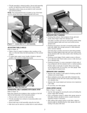
.... • After setting miter gauge square to belt (disc), adjust to desired position, then secure by tightening handle. Use back stop is located on the belt, when the belt assembly is more material at zero. Position table on the belt with both hands; For accuracy, use miter gauge... sander. Figure 11 - Back stop is well suited for both horizontal and vertical positions. Table may be at outer edge. • For accuracy, use miter gauge. Keep end butted against table and move work being sanded. ABRASIVE DISC SANDING • Abrasive disc sanding is located beneath belt ...
.... • After setting miter gauge square to belt (disc), adjust to desired position, then secure by tightening handle. Use back stop is located on the belt, when the belt assembly is more material at zero. Position table on the belt with both hands; For accuracy, use miter gauge... sander. Figure 11 - Back stop is well suited for both horizontal and vertical positions. Table may be at outer edge. • For accuracy, use miter gauge. Keep end butted against table and move work being sanded. ABRASIVE DISC SANDING • Abrasive disc sanding is located beneath belt ...


