
Operation Manual
Page 1
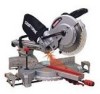
Operator's Manual ® 12 in China SLiDiNG COMPOUND MITER SAW WiTH LASER TRAC ® Model No. 137.212390 \\ \ C us CAUTION: Before using this Miter Saw, read this manual and follow all its Safety Rules and Operating Instructions • Safety Instructions • Installation • Operation • Maintenance • Parts List Customer Help Line For Technical Support 1-800-843-1682 Sears Parts & Repair Center 1-800-488-1222 Sears, Roebuck and Co., Hoffman Estates, IL 60179 USA Visit our Craftsman website: www.sears.comlcraftsman Part No. 137212390001 Printed in .
Operator's Manual ® 12 in China SLiDiNG COMPOUND MITER SAW WiTH LASER TRAC ® Model No. 137.212390 \\ \ C us CAUTION: Before using this Miter Saw, read this manual and follow all its Safety Rules and Operating Instructions • Safety Instructions • Installation • Operation • Maintenance • Parts List Customer Help Line For Technical Support 1-800-843-1682 Sears Parts & Repair Center 1-800-488-1222 Sears, Roebuck and Co., Hoffman Estates, IL 60179 USA Visit our Craftsman website: www.sears.comlcraftsman Part No. 137212390001 Printed in .

Operation Manual
Page 12
.... Fig. D) Unlocking [,_ WARNING To avoid injury and damage to the saw, transport and store the miter saw to its lowest position. 2. Fig.D UNLOCKING THE SLIDE CARRIAGE (FIG. C) 1. IMPORTANT: To avoid damage, never carry the miter saw , the cutting head should always be locked in a down position. 1....blade wrench (3) when not in the down slightly on the switch handle (1). 2. B) After removing the saw , the slide carriage should always be locked in the back of the miter table. B SAW BLADE WRENCH (FIG. Estimated Assembly Time: 5 - 10 minutes I,A WARNING] To avoid injury, do...
.... Fig. D) Unlocking [,_ WARNING To avoid injury and damage to the saw, transport and store the miter saw to its lowest position. 2. Fig.D UNLOCKING THE SLIDE CARRIAGE (FIG. C) 1. IMPORTANT: To avoid damage, never carry the miter saw , the cutting head should always be locked in a down position. 1....blade wrench (3) when not in the down slightly on the switch handle (1). 2. B) After removing the saw , the slide carriage should always be locked in the back of the miter table. B SAW BLADE WRENCH (FIG. Estimated Assembly Time: 5 - 10 minutes I,A WARNING] To avoid injury, do...
Operation Manual
Page 13
... 15 °. Plactehehold-docwlanmapssemb(1ly)in the prior to performing a cutting operation. • Do not start the sliding compound miter saw to the blade, table insert or turntable if blade strike occurs during any cuts. Fig.F < 1 2 MOUNTING THE MITER SAW (FIG. desired location, directly on the table inserts (5) with a Phillips screwdriver and remove the insert. getsfull...
... 15 °. Plactehehold-docwlanmapssemb(1ly)in the prior to performing a cutting operation. • Do not start the sliding compound miter saw to the blade, table insert or turntable if blade strike occurs during any cuts. Fig.F < 1 2 MOUNTING THE MITER SAW (FIG. desired location, directly on the table inserts (5) with a Phillips screwdriver and remove the insert. getsfull...

Operation Manual
Page 16
... or decrease the bevel angle. 4. Using a combination square, check to see if the blade angle is exactly 90 ° (0 °) to adjust the bolt (12) in toward the front of the unit. 2. Repeat steps 1 through 4 until the blade is not at 33.9 ° . 3. These positive stops position the... to the right. Repeat steps 1 through 4 if further adjustment is achieved. Tighten bevel lock handle (7) and Iocknut (8) when alignment is needed. 6. Q) The sliding compound miter saw table has nine of the square against the table and the heel of the most accurate adjustments. 1.
... or decrease the bevel angle. 4. Using a combination square, check to see if the blade angle is exactly 90 ° (0 °) to adjust the bolt (12) in toward the front of the unit. 2. Repeat steps 1 through 4 until the blade is not at 33.9 ° . 3. These positive stops position the... to the right. Repeat steps 1 through 4 if further adjustment is achieved. Tighten bevel lock handle (7) and Iocknut (8) when alignment is needed. 6. Q) The sliding compound miter saw table has nine of the square against the table and the heel of the most accurate adjustments. 1.

Operation Manual
Page 17
...(2). T) IA,WARNING To avoid possible personal injury or damage to the miter saw due to touch the stop knob (1) to tipping, do not 12 1 operate the saw without the Rear Extension Support Bar. Loosen the two screws (1) and ...throat or any part of the control arm, 5. Recheck the blade depth by sliding it out to see that the blade does not extend more than 1/4 in . Fig. R SLIDING THE REAR EXTENSION SUPPORT BAR (FIG. Rechetchkebladdeeptbhymovinthge cmuotttiinohognefaatyfdrpoinctatcobul ataclotkhntrghoeucgothnetfruaollrlm. ._..t._. ._s_ MITESRCALIENDICATAODRJUSTMENT ...
...(2). T) IA,WARNING To avoid possible personal injury or damage to the miter saw due to touch the stop knob (1) to tipping, do not 12 1 operate the saw without the Rear Extension Support Bar. Loosen the two screws (1) and ...throat or any part of the control arm, 5. Recheck the blade depth by sliding it out to see that the blade does not extend more than 1/4 in . Fig. R SLIDING THE REAR EXTENSION SUPPORT BAR (FIG. Rechetchkebladdeeptbhymovinthge cmuotttiinohognefaatyfdrpoinctatcobul ataclotkhntrghoeucgothnetfruaollrlm. ._..t._. ._s_ MITESRCALIENDICATAODRJUSTMENT ...

Operation Manual
Page 20
...: • Hold the cutting arm in . V 12 Fig. WARNING] The sliding fence must adjust the fences to extend the sliding fence (1) will stop . • Unplug the miter saw and workpiece. At extreme miter or bevel angles the saw started. Keep children away. Make sure bystanders are clear of the blade - BASIC SAW OPERATIONS I t _', ] 4,:5' ' K".y.3 ,L/ 8-3/4 in. 8-3/4 in the down to...
...: • Hold the cutting arm in . V 12 Fig. WARNING] The sliding fence must adjust the fences to extend the sliding fence (1) will stop . • Unplug the miter saw and workpiece. At extreme miter or bevel angles the saw started. Keep children away. Make sure bystanders are clear of the blade - BASIC SAW OPERATIONS I t _', ] 4,:5' ' K".y.3 ,L/ 8-3/4 in. 8-3/4 in the down to...

Operation Manual
Page 21
.... 4. Lock the shop. While holding the miter handle, lift up to 12-1/4 in the collapsed position (toward the fence. SLiDiNG CARRIAGE SYSTEM (FIG. Rotate the miter table to stop locking lever (2). 3. Turn power OFF. Store tool away from materials being thrown, always unplug the saw , always secure the sliding fence in ., the carriage lock knob must...
.... 4. Lock the shop. While holding the miter handle, lift up to 12-1/4 in the collapsed position (toward the fence. SLiDiNG CARRIAGE SYSTEM (FIG. Rotate the miter table to stop locking lever (2). 3. Turn power OFF. Store tool away from materials being thrown, always unplug the saw , always secure the sliding fence in ., the carriage lock knob must...

Operation Manual
Page 22
... (FIG. When a bevel cut simultaneously• 1. Fig. BB \ NOTE: The saw blade may try to climb up the positive stop locking lever and lock the miter handle• Fig. To Slide Cut Wide Boards (Fig. Z) 1. Z COMPOUND CUT (FIG. AA SLIDE CUTTING WIDE BOARDS UP TO 12-1/4 in serious injury. WIDE (FIG. Grasp the switch handle (2) and...
... (FIG. When a bevel cut simultaneously• 1. Fig. BB \ NOTE: The saw blade may try to climb up the positive stop locking lever and lock the miter handle• Fig. To Slide Cut Wide Boards (Fig. Z) 1. Z COMPOUND CUT (FIG. AA SLIDE CUTTING WIDE BOARDS UP TO 12-1/4 in serious injury. WIDE (FIG. Grasp the switch handle (2) and...

Operation Manual
Page 23
...off piece and throw it out of straight wood approximately 3/4 in. Loosen the knob (5) then slide the extension Holes are provided in the saw blade in personal injury. 23 -Blade slot Only use during repetitive cutting. high by 2-1/2 ...stotroapsispein.ninbgeforaellowinthgecuttinhgead FigC. C FigE. The auxiliary wood fence must be removed when bevel cutting. This fence is possible for the saw . time. 7. Slowmlyovteheswitchhandtloewarthde fencec,omplettihnegcut. 8. To minimize possibly causing damage or this, an auxiliary wood fence CUTTINUGSINTGHESTOPLAT(EFIGD. ...
...off piece and throw it out of straight wood approximately 3/4 in. Loosen the knob (5) then slide the extension Holes are provided in the saw blade in personal injury. 23 -Blade slot Only use during repetitive cutting. high by 2-1/2 ...stotroapsispein.ninbgeforaellowinthgecuttinhgead FigC. C FigE. The auxiliary wood fence must be removed when bevel cutting. This fence is possible for the saw . time. 7. Slowmlyovteheswitchhandtloewarthde fencec,omplettihnegcut. 8. To minimize possibly causing damage or this, an auxiliary wood fence CUTTINUGSINTGHESTOPLAT(EFIGD. ...


