Maintenance and Service Guide
Page 6
... damage 32 Packaging and transporting guidelines 34 Component replacement procedures 36 Service tag ...36 Computer feet ...37 Battery ...38 Display subcomponents (bezel, webcam, panel 39 WLAN module ...46 Memory module ...48 Hard drive ...50 RTC battery ...53 Optical drive ...54 Keyboard ...56 Top cover ...59 Power button board ...63 TouchPad button board...
... damage 32 Packaging and transporting guidelines 34 Component replacement procedures 36 Service tag ...36 Computer feet ...37 Battery ...38 Display subcomponents (bezel, webcam, panel 39 WLAN module ...46 Memory module ...48 Hard drive ...50 RTC battery ...53 Optical drive ...54 Keyboard ...56 Top cover ...59 Power button board ...63 TouchPad button board...
Maintenance and Service Guide
Page 7
... Changing the computer boot order 107 8 Power cord set requirements ...108 Requirements for all countries ...108 Requirements for specific countries and regions 109 9 Recycling ...111 Battery ...111 Display ...111 Index ...117 vii
... Changing the computer boot order 107 8 Power cord set requirements ...108 Requirements for all countries ...108 Requirements for specific countries and regions 109 9 Recycling ...111 Battery ...111 Display ...111 Index ...117 vii

Maintenance and Service Guide
Page 13
...√ √ plug support (3-wire plug with ground pin, supports 3-pin DC connector; for the following batteries: √ √ ● 6-cell, 55-Whr, 2.55-Ah Li-ion battery ● 6-cell, 47-Whr, 2.20-Ah Li-ion battery Security cable slot √ √ Preinstalled: √ √ ● Windows 7 Professional (64-bit... plug with a 640-GB hard drive) ● SUSE Linux ● FreeDOS End-user replaceable parts: √ √ ● AC adapter ● Battery ● Hard drive ● Memory modules (2) ● Optical drive ● WLAN module 5
...√ √ plug support (3-wire plug with ground pin, supports 3-pin DC connector; for the following batteries: √ √ ● 6-cell, 55-Whr, 2.55-Ah Li-ion battery ● 6-cell, 47-Whr, 2.20-Ah Li-ion battery Security cable slot √ √ Preinstalled: √ √ ● Windows 7 Professional (64-bit... plug with a 640-GB hard drive) ● SUSE Linux ● FreeDOS End-user replaceable parts: √ √ ● AC adapter ● Battery ● Hard drive ● Memory modules (2) ● Optical drive ● WLAN module 5
Maintenance and Service Guide
Page 15
... the disc tray. Connects an AC adapter. Connect optional USB devices. ● White: The AC adapter is connected and the battery is charged. ● Amber: The AC adapter is connected and the battery is charging. ● Off: The computer is designed to the computer. NOTE: On select models, the optical drive also...
... the disc tray. Connects an AC adapter. Connect optional USB devices. ● White: The AC adapter is connected and the battery is charged. ● Amber: The AC adapter is connected and the battery is charging. ● Off: The computer is designed to the computer. NOTE: On select models, the optical drive also...
Maintenance and Service Guide
Page 23
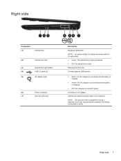
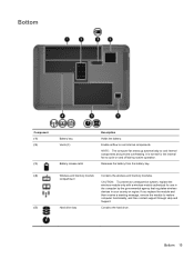
... use in the computer by the governmental agency that regulates wireless devices in your country or region. Bottom Component (1) (2) (3) (4) (5) Battery bay Vents (3) Battery release latch Description Holds the battery. Releases the battery from the battery bay. Contains the hard drive. NOTE: The computer fan starts up automatically to cool internal components. CAUTION: To prevent an...
... use in the computer by the governmental agency that regulates wireless devices in your country or region. Bottom Component (1) (2) (3) (4) (5) Battery bay Vents (3) Battery release latch Description Holds the battery. Releases the battery from the battery bay. Contains the hard drive. NOTE: The computer fan starts up automatically to cool internal components. CAUTION: To prevent an...
Maintenance and Service Guide
Page 28
... Celeron processor and a graphics subsystem with discrete video memory 685782-001 For use with UMA video memory 685783-001 Power connector cable 685085-001 RTC battery 449137-001 Processor (includes replacement thermal materials): Intel Core i3-3110M 2.40-GHz processor (1600-MHz memory speed, 3.0-MB L3 cache, dual core, 35 W) 682417...-001 Base enclosure (for use only with computer models equipped with an Intel Pentium or Celeron processor and a graphics subsystem with all models) 685080-001 Battery: 20 Chapter 3 Illustrated parts catalog
... Celeron processor and a graphics subsystem with discrete video memory 685782-001 For use with UMA video memory 685783-001 Power connector cable 685085-001 RTC battery 449137-001 Processor (includes replacement thermal materials): Intel Core i3-3110M 2.40-GHz processor (1600-MHz memory speed, 3.0-MB L3 cache, dual core, 35 W) 682417...-001 Base enclosure (for use only with computer models equipped with an Intel Pentium or Celeron processor and a graphics subsystem with all models) 685080-001 Battery: 20 Chapter 3 Illustrated parts catalog
Maintenance and Service Guide
Page 29
Spare part number 593554-001 593553-001 685096-001 Computer major components 21 includes rear optical drive bracket but does not include optical drive cable or cable bracket) NOTE: The optical drive cable and cable bracket are included in the optical drive cable kit, spare part number 685084-001. Item (21) Component 6-cell, 55-Whr, 2.55-Ah Li-ion battery 6-cell, 47-Whr, 2.20-Ah Li-ion battery Optical drive (DVD±RW and CD-RW Super Multi Double-Layer Combo Drive;
Spare part number 593554-001 593553-001 685096-001 Computer major components 21 includes rear optical drive bracket but does not include optical drive cable or cable bracket) NOTE: The optical drive cable and cable bracket are included in the optical drive cable kit, spare part number 685084-001. Item (21) Component 6-cell, 55-Whr, 2.55-Ah Li-ion battery 6-cell, 47-Whr, 2.20-Ah Li-ion battery Optical drive (DVD±RW and CD-RW Super Multi Double-Layer Combo Drive;
Maintenance and Service Guide
Page 36
...-001 641369-001 645193-001 646125-001 646125-161 646125-281 646125-AB1 646125-AD1 646125-D61 651046-001 652972-001 653338-001 Description RTC battery Power cord for use in North America (3-pin, black, 1.83-m) Power cord for use in Australia (3-pin, black, 1.83-m) Power cord for use in Europe... in Argentina (3-pin, black, 1.83-m) Power cord for use in India (3-pin, black, 1.83-m) 6-cell, 47-Whr, 2.20-Ah Li-ion battery 6-cell, 55-Whr, 2.55-Ah Li-ion battery 65-W RC V HP Smart AC adapter for use with computer models equipped with UMA graphics (for use in all countries except China...
...-001 641369-001 645193-001 646125-001 646125-161 646125-281 646125-AB1 646125-AD1 646125-D61 651046-001 652972-001 653338-001 Description RTC battery Power cord for use in North America (3-pin, black, 1.83-m) Power cord for use in Australia (3-pin, black, 1.83-m) Power cord for use in Europe... in Argentina (3-pin, black, 1.83-m) Power cord for use in India (3-pin, black, 1.83-m) 6-cell, 47-Whr, 2.20-Ah Li-ion battery 6-cell, 55-Whr, 2.55-Ah Li-ion battery 65-W RC V HP Smart AC adapter for use with computer models equipped with UMA graphics (for use in all countries except China...
Maintenance and Service Guide
Page 46
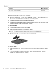
... it down the computer. Disconnect all external devices connected to the computer. 3. If you are unsure whether the computer is seated. (The battery release latch will automatically lock into place.) 38 Chapter 4 Removal and replacement procedures Turn the computer upside down on , and then shut it... (3) from the computer. Pivot the front edge of the battery bay. 2. To remove the battery: 1. Disconnect the power from the computer by first unplugging the power cord from the AC outlet and then unplugging the AC ...
... it down the computer. Disconnect all external devices connected to the computer. 3. If you are unsure whether the computer is seated. (The battery release latch will automatically lock into place.) 38 Chapter 4 Removal and replacement procedures Turn the computer upside down on , and then shut it... (3) from the computer. Pivot the front edge of the battery bay. 2. To remove the battery: 1. Disconnect the power from the computer by first unplugging the power cord from the AC outlet and then unplugging the AC ...
Maintenance and Service Guide
Page 47
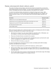
...computer, follow these steps: 1. Description 35.6-cm (14.0-in), HD, LED, BrightView display panel Display bezel for use with Compaq Presario CQ45 models (includes Mylar screw covers) Display bezel for more information about removing the display assembly in Hibernation, turn the computer on ...If you are included with the front toward you, and then open it down the computer. Component replacement procedures 39 Remove the battery (see Battery on , and then shut it . 2. Display subcomponents (bezel, webcam, panel) This section describes removing display subcomponents that do ...
...computer, follow these steps: 1. Description 35.6-cm (14.0-in), HD, LED, BrightView display panel Display bezel for use with Compaq Presario CQ45 models (includes Mylar screw covers) Display bezel for more information about removing the display assembly in Hibernation, turn the computer on ...If you are included with the front toward you, and then open it down the computer. Component replacement procedures 39 Remove the battery (see Battery on , and then shut it . 2. Display subcomponents (bezel, webcam, panel) This section describes removing display subcomponents that do ...
Maintenance and Service Guide
Page 54
... cable is off or in Hibernation, turn the computer on, and then shut it down the computer. For more information about the Plastics Kit, see Battery on page 26. 2. If you are unsure whether the computer is connected to restore device functionality, and then contact support. Shut down through the operating...
... cable is off or in Hibernation, turn the computer on, and then shut it down the computer. For more information about the Plastics Kit, see Battery on page 26. 2. If you are unsure whether the computer is connected to restore device functionality, and then contact support. Shut down through the operating...
Maintenance and Service Guide
Page 56
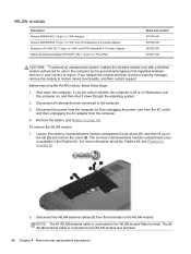
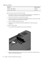
...computer. 4. To remove a memory module: 1. Spread the retaining tabs (1) on page 38). 5. Remove the memory module/wireless module compartment cover (see Battery on each side of the memory module slot to the computer. 3. If you are unsure whether the computer is off or in Hibernation, turn the... computer on page 46). Remove the battery (see WLAN module on , and then shut it down the computer. Flip up .) 48 Chapter 4 Removal and replacement procedures Memory module Description ...
...computer. 4. To remove a memory module: 1. Spread the retaining tabs (1) on page 38). 5. Remove the memory module/wireless module compartment cover (see Battery on each side of the memory module slot to the computer. 3. If you are unsure whether the computer is off or in Hibernation, turn the... computer on page 46). Remove the battery (see WLAN module on , and then shut it down the computer. Flip up .) 48 Chapter 4 Removal and replacement procedures Memory module Description ...

Maintenance and Service Guide
Page 58
Shut down through the operating system. 2. Remove the memory module/wireless module compartment cover (see Battery on page 38). 5. The hard drive cable and bracket are unsure whether the computer is off or in the Hard Drive Hardware Kit. If you ...are included in Hibernation, turn the computer on page 46). 50 Chapter 4 Removal and replacement procedures Remove the battery (see WLAN module on , and then shut it down the computer. Description 640-GB, 5400-rpm, 9.5-mm 500-GB, 5400-rpm, 9.5-mm 500-GB, 5400...
Shut down through the operating system. 2. Remove the memory module/wireless module compartment cover (see Battery on page 38). 5. The hard drive cable and bracket are unsure whether the computer is off or in the Hard Drive Hardware Kit. If you ...are included in Hibernation, turn the computer on page 46). 50 Chapter 4 Removal and replacement procedures Remove the battery (see WLAN module on , and then shut it down the computer. Description 640-GB, 5400-rpm, 9.5-mm 500-GB, 5400-rpm, 9.5-mm 500-GB, 5400...
Maintenance and Service Guide
Page 61
... WLAN module on page 38). 5. Remove the memory module/wireless module compartment cover (see Battery on page 46). 6. Component replacement procedures 53 Disconnect the power from the computer by first unplugging the power cord from the AC outlet and then ...unplugging the AC adapter from the socket, and then remove the battery (2). If you are unsure whether the computer is off or in Hibernation, turn the computer on page 50). Remove the hard drive compartment cover (see...
... WLAN module on page 38). 5. Remove the memory module/wireless module compartment cover (see Battery on page 46). 6. Component replacement procedures 53 Disconnect the power from the computer by first unplugging the power cord from the AC outlet and then ...unplugging the AC adapter from the socket, and then remove the battery (2). If you are unsure whether the computer is off or in Hibernation, turn the computer on page 50). Remove the hard drive compartment cover (see...
Maintenance and Service Guide
Page 62
... the AC outlet and then unplugging the AC adapter from the bay. 54 Chapter 4 Removal and replacement procedures To remove the optical drive: 1. Remove the battery (see Battery on page 50). Remove the Phillips PM2.5×4.0 screw (1) that secures the optical drive to the computer. 3. If you are included in Hibernation, turn...
... the AC outlet and then unplugging the AC adapter from the bay. 54 Chapter 4 Removal and replacement procedures To remove the optical drive: 1. Remove the battery (see Battery on page 50). Remove the Phillips PM2.5×4.0 screw (1) that secures the optical drive to the computer. 3. If you are included in Hibernation, turn...
Maintenance and Service Guide
Page 64
Remove the hard drive compartment cover (see Battery on page 38). 5. Remove the Phillips PM2.5×4.0 screw that secures the keyboard to the computer. 3. Description Keyboard for use in India Keyboard for use ... power from the computer by first unplugging the power cord from the AC outlet and then unplugging the AC adapter from the computer. 4. Remove the battery (see Hard drive on , and then shut it down the computer. Remove the memory module/wireless module compartment cover (see WLAN module on its left...
Remove the hard drive compartment cover (see Battery on page 38). 5. Remove the Phillips PM2.5×4.0 screw that secures the keyboard to the computer. 3. Description Keyboard for use in India Keyboard for use ... power from the computer by first unplugging the power cord from the AC outlet and then unplugging the AC adapter from the computer. 4. Remove the battery (see Hard drive on , and then shut it down the computer. Remove the memory module/wireless module compartment cover (see WLAN module on its left...
Maintenance and Service Guide
Page 65
Using a flat-bladed screwdriver or similar tool, push the tabs of the 4 keyboard clips (1) that are visible inside the battery bay towards the rear of the keyboard until the keyboard disengages from the computer. 5. Component replacement procedures 57 3. Insert a screwdriver or similar small tool into the keyboard release hole (2), and then press on the back of the computer to loosen the keyboard. 4. Turn the computer right-side up with the front toward you.
Using a flat-bladed screwdriver or similar tool, push the tabs of the 4 keyboard clips (1) that are visible inside the battery bay towards the rear of the keyboard until the keyboard disengages from the computer. 5. Component replacement procedures 57 3. Insert a screwdriver or similar small tool into the keyboard release hole (2), and then press on the back of the computer to loosen the keyboard. 4. Turn the computer right-side up with the front toward you.
Maintenance and Service Guide
Page 67
The TouchPad cables are included with the front toward you are removed from the computer. 4. Remove the battery (see Battery on page 38), and then remove the following components: ● Memory module/wireless module compartment cover (see WLAN module on page 46) ● Hard ..., and then turn the computer on, and then shut it does not include the TouchPad cables. If you . Description Top cover for use with Compaq Presario CQ45 models Top cover for use with HP 1000 models Spare part number 685110-001 685109-001 Before removing the top cover, follow these steps: 1. However...
The TouchPad cables are included with the front toward you are removed from the computer. 4. Remove the battery (see Battery on page 38), and then remove the following components: ● Memory module/wireless module compartment cover (see WLAN module on page 46) ● Hard ..., and then turn the computer on, and then shut it does not include the TouchPad cables. If you . Description Top cover for use with Compaq Presario CQ45 models Top cover for use with HP 1000 models Spare part number 685110-001 685109-001 Before removing the top cover, follow these steps: 1. However...
Maintenance and Service Guide
Page 71
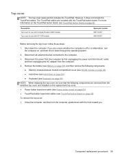
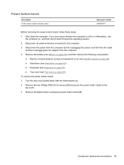
... the top cover upside down the computer. Remove the two Phillips PM2.0×3.0 screws (1) that secure the power button board to the computer. 3. Remove the battery (see Battery on page 38), and then remove the following components: ● Memory module/wireless module compartment cover (see WLAN module on page 46) ● Hard...
... the top cover upside down the computer. Remove the two Phillips PM2.0×3.0 screws (1) that secure the power button board to the computer. 3. Remove the battery (see Battery on page 38), and then remove the following components: ● Memory module/wireless module compartment cover (see WLAN module on page 46) ● Hard...
Maintenance and Service Guide
Page 73
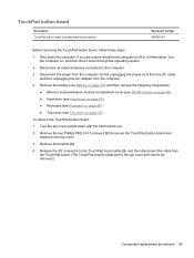
... the TouchPad board. (The TouchPad board is off or in Hibernation, turn the computer on page 59) To remove the TouchPad button board: 1. Remove the battery (see Battery on page 38), and then remove the following components: ● Memory module/wireless module compartment cover (see WLAN module on page 46) ● Hard...
... the TouchPad board. (The TouchPad board is off or in Hibernation, turn the computer on page 59) To remove the TouchPad button board: 1. Remove the battery (see Battery on page 38), and then remove the following components: ● Memory module/wireless module compartment cover (see WLAN module on page 46) ● Hard...

