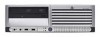
Safety and Regulatory Information Desktops, Thin Clients, and Personal Workstations
Page 5
... ...10 TV Antenna Connectors Protection ...11 External Television Antenna Grounding 11 Lightning Protection ...11 ENWW v Table of contents 1 Safety Notices Important Safety Information ...1 Installation Conditions ...2 Battery Replacement Notice ...2 Headset and Earphone Volume Level Notice 3 German Ergonomics Notice ...3 Laser Safety ...3 CDRH Regulations ...3 Compliance with International Regulations 4 Laser Product Label ...4 Laser Information ...4 Power Supply...
... ...10 TV Antenna Connectors Protection ...11 External Television Antenna Grounding 11 Lightning Protection ...11 ENWW v Table of contents 1 Safety Notices Important Safety Information ...1 Installation Conditions ...2 Battery Replacement Notice ...2 Headset and Earphone Volume Level Notice 3 German Ergonomics Notice ...3 Laser Safety ...3 CDRH Regulations ...3 Compliance with International Regulations 4 Laser Product Label ...4 Laser Information ...4 Power Supply...
Safety and Regulatory Information Desktops, Thin Clients, and Personal Workstations
Page 8
... of in sales, giveaways, or promotions. For more information about removing a battery, refer to the instructions. • Replace only with the HP spare designated for proper battery disposal. 2 Chapter 1 Safety Notices ENWW HP encourages customers to recycle used batteries according to your computer documentation. Batteries, battery packs, and accumulators should not be inside the computer. WARNING! Disconnect power...
... of in sales, giveaways, or promotions. For more information about removing a battery, refer to the instructions. • Replace only with the HP spare designated for proper battery disposal. 2 Chapter 1 Safety Notices ENWW HP encourages customers to recycle used batteries according to your computer documentation. Batteries, battery packs, and accumulators should not be inside the computer. WARNING! Disconnect power...

Hardware Reference Guide - dc7600 CMT
Page 4
... an Optical or other Removable Storage Device 2-24 Installing a SATA Hard Drive into a 3.5-inch Drive Bay 2-27 Removing a Drive from the Drive Bay 2-30 A Specifications B Battery Replacement C Security Lock Provisions Installing a Security Lock C-1 Cable Lock C-1 Padlock C-2 Universal Chassis Clamp Lock C-3 D Electrostatic Discharge Preventing Electrostatic Damage D-1 Grounding Methods D-1 E Computer Operating Guidelines, Routine Care...
... an Optical or other Removable Storage Device 2-24 Installing a SATA Hard Drive into a 3.5-inch Drive Bay 2-27 Removing a Drive from the Drive Bay 2-30 A Specifications B Battery Replacement C Security Lock Provisions Installing a Security Lock C-1 Cable Lock C-1 Padlock C-2 Universal Chassis Clamp Lock C-3 D Electrostatic Discharge Preventing Electrostatic Damage D-1 Grounding Methods D-1 E Computer Operating Guidelines, Routine Care...

Hardware Reference Guide - dc7600 CMT
Page 52
.... There is a risk of fire and burns if the battery is removed or replaced, the CMOS settings will be cleared. Hardware Reference Guide www.hp.com B-1 Refer to the battery originally installed in fire or water. ■ Replace the battery only with the general household waste. N Batteries, battery packs, and accumulators should not be disposed of together with...
.... There is a risk of fire and burns if the battery is removed or replaced, the CMOS settings will be cleared. Hardware Reference Guide www.hp.com B-1 Refer to the battery originally installed in fire or water. ■ Replace the battery only with the general household waste. N Batteries, battery packs, and accumulators should not be disposed of together with...

Hardware Reference Guide - dc7600 CMT
Page 53
If you are discharged of battery holder on the system board. 4. Locate the battery and battery holder on the system board, complete the following instructions to replace the battery. Depending on the type of static electricity by briefly touching a grounded metal object. 1. Lift the battery out of the computer or optional equipment. B-2 www.hp.com Hardware Reference Guide...
If you are discharged of battery holder on the system board. 4. Locate the battery and battery holder on the system board, complete the following instructions to replace the battery. Depending on the type of static electricity by briefly touching a grounded metal object. 1. Lift the battery out of the computer or optional equipment. B-2 www.hp.com Hardware Reference Guide...

Hardware Reference Guide - dc7600 CMT
Page 54
To release the battery from its holder, squeeze the metal clamp that extends above one edge of the replacement battery under the holder's lip with the positive side up , lift it out 1. Push the other edge down until the clamp snaps over the other edge of the battery. To insert the new battery, slide one edge of the battery 2. Battery Replacement Type 2 a. When the battery pops up . Removing and Replacing a Coin Cell Battery (Type 2) Hardware Reference Guide www.hp.com B-3 b.
To release the battery from its holder, squeeze the metal clamp that extends above one edge of the replacement battery under the holder's lip with the positive side up , lift it out 1. Push the other edge down until the clamp snaps over the other edge of the battery. To insert the new battery, slide one edge of the battery 2. Battery Replacement Type 2 a. When the battery pops up . Removing and Replacing a Coin Cell Battery (Type 2) Hardware Reference Guide www.hp.com B-3 b.

Hardware Reference Guide - dc7600 CMT
Page 55
... Computer Setup to complete this procedure. 5. Pull back on the clip 1 that is holding the battery in the computer and turn on the Documentation and Diagnostics CD. 8. Replace the computer access panel. 6. B-4 www.hp.com Hardware Reference Guide If you normally lock the Smart Cover Lock, use the following steps to relock the...
... Computer Setup to complete this procedure. 5. Pull back on the clip 1 that is holding the battery in the computer and turn on the Documentation and Diagnostics CD. 8. Replace the computer access panel. 6. B-4 www.hp.com Hardware Reference Guide If you normally lock the Smart Cover Lock, use the following steps to relock the...

Hardware Reference Guide - dc7600 CMT
Page 67
Index A access panel locking and unlocking 2-2, C-1 removing 2-4 application key 1-4 audio connectors 1-2, 1-3 B battery replacement B-1 bezel See front bezel C CD-ROM drive See optical drive changing computer configuration 1-7, 1-10 components front panel 1-2 keyboard 1-4 rear panel 1-3 computer access panel...discharge, preventing damage D-1 expansion card installing 2-15 PCI 2-15 PCI Express 2-15, 2-19 removing 2-15 slot locations 2-15 expansion slot cover removing 2-17 replacing 2-19 F front bezel blanks 2-8 removing 2-6 replacing 2-7 front panel components 1-2 Hardware Reference Guide www...
Index A access panel locking and unlocking 2-2, C-1 removing 2-4 application key 1-4 audio connectors 1-2, 1-3 B battery replacement B-1 bezel See front bezel C CD-ROM drive See optical drive changing computer configuration 1-7, 1-10 components front panel 1-2 keyboard 1-4 rear panel 1-3 computer access panel...discharge, preventing damage D-1 expansion card installing 2-15 PCI 2-15 PCI Express 2-15, 2-19 removing 2-15 slot locations 2-15 expansion slot cover removing 2-17 replacing 2-19 F front bezel blanks 2-8 removing 2-6 replacing 2-7 front panel components 1-2 Hardware Reference Guide www...

HP Compaq Business PC dc7600 Series Personal Computer Illustrated Parts Map, CMT Chassis (1st Edition)
Page 2
...ATA (SATA) Port connector Third Serial ATA (SATA) Port connector Fourth Serial ATA (SATA) Port connector CPU fan Hood lock Hood sensor Battery Memory socket Memory socket Memory socket Memory socket Microprocessor socket Clearing CMOS The computer's configuration (CMOS) may damage the system board. 2. Remove... Options Note: See the Computer Setup (F10) Utility Guide on the Documentation and Diagnostics CD. If it is, it is resolved. Replace the access panel. 5. Turn off CPU thermal shutdown CPU not installed Power supply overload (crow bar) Defective or missing memory Defective or...
...ATA (SATA) Port connector Third Serial ATA (SATA) Port connector Fourth Serial ATA (SATA) Port connector CPU fan Hood lock Hood sensor Battery Memory socket Memory socket Memory socket Memory socket Microprocessor socket Clearing CMOS The computer's configuration (CMOS) may damage the system board. 2. Remove... Options Note: See the Computer Setup (F10) Utility Guide on the Documentation and Diagnostics CD. If it is, it is resolved. Replace the access panel. 5. Turn off CPU thermal shutdown CPU not installed Power supply overload (crow bar) Defective or missing memory Defective or...

HP Compaq dx 7200 and dc7600 Personal Computers, Technical Reference Guide, 1st Edition
Page 73
...be directly accessed using conventional OUT and IN assembly language instructions through I/O ports 70h/71h, although the suggested method is replaced with a Renata CR2032 or equivalent 3-VDC lithium battery. 4.4.1 Clearing CMOS The contents of Week 05h Hours (Alarm) 04h Hours (Timer) 03h Minutes (Alarm) 02h ... 7. The RTC uses the first 14 bytes (00-0Dh) of battery-backed RAM divided into two 128-byte configuration memory areas. The battery is used for at least 5 seconds. 5. Technical Reference Guide www.hp.com 4-19 System Support 4.4 Real-Time Clock and Configuration Memory The...
...be directly accessed using conventional OUT and IN assembly language instructions through I/O ports 70h/71h, although the suggested method is replaced with a Renata CR2032 or equivalent 3-VDC lithium battery. 4.4.1 Clearing CMOS The contents of Week 05h Hours (Alarm) 04h Hours (Timer) 03h Minutes (Alarm) 02h ... 7. The RTC uses the first 14 bytes (00-0Dh) of battery-backed RAM divided into two 128-byte configuration memory areas. The battery is used for at least 5 seconds. 5. Technical Reference Guide www.hp.com 4-19 System Support 4.4 Real-Time Clock and Configuration Memory The...

HP Compaq dx 7200 and dc7600 Personal Computers, Technical Reference Guide, 1st Edition
Page 75
...Provision These systems include a chassis cutout (on the rear panel) for a "cover removed" condition: Technical Reference Guide www.hp.com 4-21 The battery-backed logic will record this function to be always changeable or changeable only by the user will require that all system board ...plunger switch that is stored in the appropriate User Guide or Maintainance And Service Reference Guide. To re-enable the password feature, repeat steps 1-6, replacing the jumper on pins 1 and 2 of the system unit. Turn off (not illuminated). 3. In addition, the ability to write to ...
...Provision These systems include a chassis cutout (on the rear panel) for a "cover removed" condition: Technical Reference Guide www.hp.com 4-21 The battery-backed logic will record this function to be always changeable or changeable only by the user will require that all system board ...plunger switch that is stored in the appropriate User Guide or Maintainance And Service Reference Guide. To re-enable the password feature, repeat steps 1-6, replacing the jumper on pins 1 and 2 of the system unit. Turn off (not illuminated). 3. In addition, the ability to write to ...

Troubleshooting Guide
Page 18
... dealer or reseller for at least four seconds until the computer turns off when the power button is in Computer Setup. 2-6 www.hp.com Troubleshooting Guide The Num Lock key can also be used to easily resolve the general problems described in this section. Press and... Computer appears locked up . Disconnect the power cord from standby mode, do not hold the power button for RTC battery replacement. RTC (real-time clock) battery may need to be replaced. ✎ Connecting the computer to resume from the electrical outlet. First, reset the date and time under Control ...
... dealer or reseller for at least four seconds until the computer turns off when the power button is in Computer Setup. 2-6 www.hp.com Troubleshooting Guide The Num Lock key can also be used to easily resolve the general problems described in this section. Press and... Computer appears locked up . Disconnect the power cord from standby mode, do not hold the power button for RTC battery replacement. RTC (real-time clock) battery may need to be replaced. ✎ Connecting the computer to resume from the electrical outlet. First, reset the date and time under Control ...

Troubleshooting Guide
Page 39
...restart the computer. After the shutdown is in standby mode. Check the software, if available, for terms and conditions. Check/replace device batteries. 3. The Shut Down Windows dialog box is not properly connected. 1. Program in the following table. Solving Keyboard Problems ...for more than four seconds. Wireless device error. 1. Computer is complete, reconnect the keyboard to commands. Troubleshooting Guide www.hp.com 2-27 Troubleshooting Without Diagnostics Solving Keyboard and Mouse Problems If you will shut down and you encounter keyboard or mouse...
...restart the computer. After the shutdown is in standby mode. Check the software, if available, for terms and conditions. Check/replace device batteries. 3. The Shut Down Windows dialog box is not properly connected. 1. Program in the following table. Solving Keyboard Problems ...for more than four seconds. Wireless device error. 1. Computer is complete, reconnect the keyboard to commands. Troubleshooting Guide www.hp.com 2-27 Troubleshooting Without Diagnostics Solving Keyboard and Mouse Problems If you will shut down and you encounter keyboard or mouse...

Troubleshooting Guide
Page 41
... data. Press the power button to resume from standby mode. Ä CAUTION: When attempting to movement or is jerky. Check/replace device batteries. 3. Computer is dirty. Otherwise, the computer will only move vertically, horizontally, or movement is too slow. (continued) Wireless ...device error. 1. Mouse roller ball is in standby mode. Troubleshooting Guide www.hp.com 2-29 Check the software, if available, for more ...
... data. Press the power button to resume from standby mode. Ä CAUTION: When attempting to movement or is jerky. Check/replace device batteries. 3. Computer is dirty. Otherwise, the computer will only move vertically, horizontally, or movement is too slow. (continued) Wireless ...device error. 1. Mouse roller ball is in standby mode. Troubleshooting Guide www.hp.com 2-29 Check the software, if available, for more ...

Troubleshooting Guide
Page 61
... option ROM. Reset the date and time under Control Panel (Computer Setup can also be used for RTC battery replacement. If the problem persists, replace the RTC battery. Internal PXE option ROM is enabled 162-System Options Not Set Configuration incorrect. Reset the date and time under...1. Troubleshooting Guide www.hp.com A-3 In Computer Setup, set Advanced > Device Options > NIC PXE Option ROM Download to DISABLE to prevent PXE option ROM for the internal NIC from the NIC to a PXE server. 3. If the problem persists, replace the RTC battery. POST Error Messages Numeric...
... option ROM. Reset the date and time under Control Panel (Computer Setup can also be used for RTC battery replacement. If the problem persists, replace the RTC battery. Internal PXE option ROM is enabled 162-System Options Not Set Configuration incorrect. Reset the date and time under...1. Troubleshooting Guide www.hp.com A-3 In Computer Setup, set Advanced > Device Options > NIC PXE Option ROM Download to DISABLE to prevent PXE option ROM for the internal NIC from the NIC to a PXE server. 3. If the problem persists, replace the RTC battery. POST Error Messages Numeric...

Troubleshooting Guide
Page 83
Index A access panel, removing 2-7 audible codes A-12 audio problems 2-23 B battery, replacing 2-6 beep codes A-12 blank screen 2-18 booting options Full Boot A-1 Quick Boot A-1 C CD-ROM or DVD problems 2-39 CMOS backing up B-1 button B-1, B-3 clearing and resetting B-3 ... blinking power A-12 blinking PS/2 keyboard A-12 M memory error codes A-4 solving problems 2-37 monitor blank screen 2-18 blurry video 2-20 checking connections 2-5 Troubleshooting Guide www.hp.com Index-1
Index A access panel, removing 2-7 audible codes A-12 audio problems 2-23 B battery, replacing 2-6 beep codes A-12 blank screen 2-18 booting options Full Boot A-1 Quick Boot A-1 C CD-ROM or DVD problems 2-39 CMOS backing up B-1 button B-1, B-3 clearing and resetting B-3 ... blinking power A-12 blinking PS/2 keyboard A-12 M memory error codes A-4 solving problems 2-37 monitor blank screen 2-18 blurry video 2-20 checking connections 2-5 Troubleshooting Guide www.hp.com Index-1

Getting Started
Page 20
...Key in Computer Setup. The Smart Cover FailSafe Key, a device for RTC battery replacement. See the Hardware Reference Guide on the Documentation and Diagnostics CD for instructions on installing a new battery, or contact an authorized dealer or reseller for manually disabling the Smart Cover Lock...from HP. Getting Started Solving General Problems (Continued) Problem Cause Solution Computer date and time display is not available on . You will not move using Computer Setup. The Num Lock key can also be on the keypad. If the problem persists, replace the RTC battery. ...
...Key in Computer Setup. The Smart Cover FailSafe Key, a device for RTC battery replacement. See the Hardware Reference Guide on the Documentation and Diagnostics CD for instructions on installing a new battery, or contact an authorized dealer or reseller for manually disabling the Smart Cover Lock...from HP. Getting Started Solving General Problems (Continued) Problem Cause Solution Computer date and time display is not available on . You will not move using Computer Setup. The Num Lock key can also be on the keypad. If the problem persists, replace the RTC battery. ...

Getting Started - Enhanced for Accessibility
Page 20
.... The Num Lock light should not be on the keypad. Cannot remove computer cover or access panel. If the problem persists, replace the RTC battery. Cursor will need to be used to update the RTC date and time). Unlock the Smart Cover Lock using the arrow keys ... life of forgotten password, power loss, or computer malfunction. 16 www.hp.com Getting Started You will not move using Computer Setup. See the Hardware Reference Guide on the Documentation and Diagnostics CD for RTC battery replacement. The Smart Cover FailSafe Key, a device for manually disabling the Smart...
.... The Num Lock light should not be on the keypad. Cannot remove computer cover or access panel. If the problem persists, replace the RTC battery. Cursor will need to be used to update the RTC date and time). Unlock the Smart Cover Lock using the arrow keys ... life of forgotten password, power loss, or computer malfunction. 16 www.hp.com Getting Started You will not move using Computer Setup. See the Hardware Reference Guide on the Documentation and Diagnostics CD for RTC battery replacement. The Smart Cover FailSafe Key, a device for manually disabling the Smart...

Hardware Guide
Page 57
... the Smart Cover Sensor. 2. Lift the battery out of battery holder on the system board, complete the following instructions to the battery. 3. Removing a Coin Cell Battery (Type 1) b. Disconnect the power cord from the power outlet and disconnect any external devices. Slide the replacement battery into position, positive side up. B-2 www.hp.com Hardware Reference Guide Depending on...
... the Smart Cover Sensor. 2. Lift the battery out of battery holder on the system board, complete the following instructions to the battery. 3. Removing a Coin Cell Battery (Type 1) b. Disconnect the power cord from the power outlet and disconnect any external devices. Slide the replacement battery into position, positive side up. B-2 www.hp.com Hardware Reference Guide Depending on...

Hardware Guide
Page 58
Removing and Replacing a Coin Cell Battery (Type 2) Hardware Reference Guide www.hp.com B-3 When the battery pops up . Push the other edge down until the clamp snaps over the other edge of the replacement battery under the holder's lip with the positive side up , lift it out 1. b. To insert the new battery, slide one edge of the battery. Battery Replacement Type 2 a. To release the battery from its holder, squeeze the metal clamp that extends above one edge of the battery 2.
Removing and Replacing a Coin Cell Battery (Type 2) Hardware Reference Guide www.hp.com B-3 When the battery pops up . Push the other edge down until the clamp snaps over the other edge of the replacement battery under the holder's lip with the positive side up , lift it out 1. b. To insert the new battery, slide one edge of the battery. Battery Replacement Type 2 a. To release the battery from its holder, squeeze the metal clamp that extends above one edge of the battery 2.

