Hardware Guide
Page 3
... Memory 2-7 DIMMs 2-7 DDR-SDRAM DIMMs 2-7 Installing DDR-SDRAM DIMMs 2-8 Removing the Expansion Card Cage 2-11 Installing an Expansion Card 2-12 Removing the AGP Card 2-15 Drive Positions 2-17 Installing Additional Drives 2-18 Upgrading the Hard Drive 2-18 Removing an Optical Drive 2-20 Installing an Optional Optical Drive 2-22 Hardware Reference Guide iii
... Memory 2-7 DIMMs 2-7 DDR-SDRAM DIMMs 2-7 Installing DDR-SDRAM DIMMs 2-8 Removing the Expansion Card Cage 2-11 Installing an Expansion Card 2-12 Removing the AGP Card 2-15 Drive Positions 2-17 Installing Additional Drives 2-18 Upgrading the Hard Drive 2-18 Removing an Optical Drive 2-20 Installing an Optional Optical Drive 2-22 Hardware Reference Guide iii
Hardware Guide
Page 4
Contents Working with the MultiBay 2-24 "Hot-Plugging" or "Hot-Swapping" MultiBay Drives 2-25 Partitioning and Formatting a MultiBay Hard Drive 2-25 Uninstalling the MultiBay Security Screw 2-26 Inserting a Drive into the MultiBay 2-26 Removing a Drive from the MultiBay 2-27 A Specifications B Hard Drive Installation Guidelines Using the Cable-Select Feature with Ultra ATA Devices B-1 Guidelines for Installing Ultra ATA...
Contents Working with the MultiBay 2-24 "Hot-Plugging" or "Hot-Swapping" MultiBay Drives 2-25 Partitioning and Formatting a MultiBay Hard Drive 2-25 Uninstalling the MultiBay Security Screw 2-26 Inserting a Drive into the MultiBay 2-26 Removing a Drive from the MultiBay 2-27 A Specifications B Hard Drive Installation Guidelines Using the Cable-Select Feature with Ultra ATA Devices B-1 Guidelines for Installing Ultra ATA...
Hardware Guide
Page 7
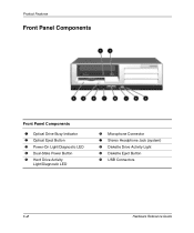
USB Connectors 1-2 Hardware Reference Guide Product Features Front Panel Components Front Panel Components 1 Optical Drive Busy Indicator 2 Optical Eject Button 3 Power-On Light/Diagnostic LED 4 Dual-State Power Button 5 Hard Drive Activity Light/Diagnostic LED 6 Microphone Connector 7 Stereo Headphone Jack (system) 8 Diskette Drive Activity Light 9 Diskette Eject Button -
USB Connectors 1-2 Hardware Reference Guide Product Features Front Panel Components Front Panel Components 1 Optical Drive Busy Indicator 2 Optical Eject Button 3 Power-On Light/Diagnostic LED 4 Dual-State Power Button 5 Hard Drive Activity Light/Diagnostic LED 6 Microphone Connector 7 Stereo Headphone Jack (system) 8 Diskette Drive Activity Light 9 Diskette Eject Button -
Hardware Guide
Page 10
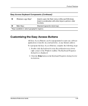
... the Windows taskbar. Product Features Easy Access Keyboard Components (Continued) 8 Windows Logo Keys* Used to open any Internet address. Click the Help button on your hard drive, or any software application or data file on the Keyboard Properties dialog box for instructions. Hardware Reference Guide 1-5
... the Windows taskbar. Product Features Easy Access Keyboard Components (Continued) 8 Windows Logo Keys* Used to open any Internet address. Click the Help button on your hard drive, or any software application or data file on the Keyboard Properties dialog box for instructions. Hardware Reference Guide 1-5
Hardware Guide
Page 29
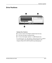
Refer to the Computer Setup (F10) Utility Guide for optional drives 3 3.5-inch, third-height, standard, 1.44-MB diskette drive To verify the type, size, and capacity of the storage devices installed in your computer, run Compaq Computer Setup. Hardware Reference Guide 2-17 Drive Positions Hardware Upgrades Desktop Drive Positions 1 3.5-inch, internal, third-height, standard hard drive bay 2 5.25-inch drive bay for more information.
Refer to the Computer Setup (F10) Utility Guide for optional drives 3 3.5-inch, third-height, standard, 1.44-MB diskette drive To verify the type, size, and capacity of the storage devices installed in your computer, run Compaq Computer Setup. Hardware Reference Guide 2-17 Drive Positions Hardware Upgrades Desktop Drive Positions 1 3.5-inch, internal, third-height, standard hard drive bay 2 5.25-inch drive bay for more information.
Hardware Guide
Page 30
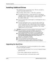
...that you are inserting or removing a hard drive, shut down the operating system properly, then turn off the computer and any external devices. 3. Disconnect the power cord from the power outlet. 2-18 Hardware Reference Guide I Handle a drive carefully; Compaq has provided extra guide screws, installed ...in the front of the computer. I Do not use metric hardware. do not drop it. le: Upgrading the Hard Drive The 3.5-inch hard drive is on the right side of the computer ...
...that you are inserting or removing a hard drive, shut down the operating system properly, then turn off the computer and any external devices. 3. Disconnect the power cord from the power outlet. 2-18 Hardware Reference Guide I Handle a drive carefully; Compaq has provided extra guide screws, installed ...in the front of the computer. I Do not use metric hardware. do not drop it. le: Upgrading the Hard Drive The 3.5-inch hard drive is on the right side of the computer ...
Hardware Guide
Page 31
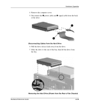
Disconnect the 1 power cable and 2 signal cable from the Rear of the Chassis) Hardware Reference Guide 2-19 Removing the Hard Drive (Shown from the back of the bay, then lift the drive from the bay. Pull the drive release latch away from the Hard Drive 6. Remove the computer cover. 5. Disconnecting Cables from the drive. 7. Hardware Upgrades 4. Slide the drive to the rear of the drive.
Disconnect the 1 power cable and 2 signal cable from the Rear of the Chassis) Hardware Reference Guide 2-19 Removing the Hard Drive (Shown from the back of the bay, then lift the drive from the bay. Pull the drive release latch away from the Hard Drive 6. Remove the computer cover. 5. Disconnecting Cables from the drive. 7. Hardware Upgrades 4. Slide the drive to the rear of the drive.
Hardware Guide
Page 32
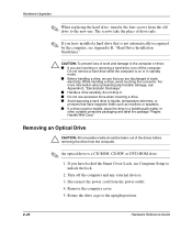
... a bubble-pack mailer or other suitable protective packaging and label the package "Fragile: Handle With Care." I If you have installed a hard drive that you have magnetic fields such as monitors or speakers. I Do not use Computer Setup to the new one. Remove the computer cover...Hardware Upgrades ✎ When replacing the hard drive, transfer the four screws from the computer. ✎ An optical drive is a CD-ROM, CD-RW, or DVD-ROM drive. 1. I If a drive must be taken out of the drives before removing the drive from the old drive to unlock the lock. 2. Disconnect the...
... a bubble-pack mailer or other suitable protective packaging and label the package "Fragile: Handle With Care." I If you have installed a hard drive that you have magnetic fields such as monitors or speakers. I Do not use Computer Setup to the new one. Remove the computer cover...Hardware Upgrades ✎ When replacing the hard drive, transfer the four screws from the computer. ✎ An optical drive is a CD-ROM, CD-RW, or DVD-ROM drive. 1. I If a drive must be taken out of the drives before removing the drive from the old drive to unlock the lock. 2. Disconnect the...
Hardware Guide
Page 36
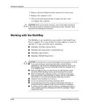
... you are placed in their proper locations during the reassembly process. Working with the MultiBay The MultiBay is a special drive bay that you are inserting or removing a hard drive, exit all software applications, shut down the operating system software, and turn off the computer. It is pre-installed in... extremes, or products that no media, such as monitors or speakers. I If a drive must be mailed, place the drive in the drive and that the media tray is in a bubble-pack mailer or other than a hard drive, make sure that have magnetic fields such as a CD-ROM or DVD-ROM, is...
... you are placed in their proper locations during the reassembly process. Working with the MultiBay The MultiBay is a special drive bay that you are inserting or removing a hard drive, exit all software applications, shut down the operating system software, and turn off the computer. It is pre-installed in... extremes, or products that no media, such as monitors or speakers. I If a drive must be mailed, place the drive in the drive and that the media tray is in a bubble-pack mailer or other than a hard drive, make sure that have magnetic fields such as a CD-ROM or DVD-ROM, is...
Hardware Guide
Page 37
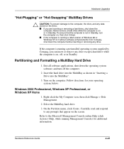
...computer. 2. If the computer is running a preinstalled operating system supplied by Compaq, you are inserting or removing a hard drive, shut down the computer. Carefully read and respond to any data stored on the drive: I If the computer is not in Standby, turn off , or in...version of Windows 98 or Windows NT 4.0 without software enhancements from Compaq, shut down the computer before inserting or removing any drive except a hard drive while the computer is on or in Standby. Select the MultiBay hard drive. 3. Refer to the Microsoft Management Console online Help (click Action ...
...computer. 2. If the computer is running a preinstalled operating system supplied by Compaq, you are inserting or removing a hard drive, shut down the computer. Carefully read and respond to any data stored on the drive: I If the computer is not in Standby, turn off , or in...version of Windows 98 or Windows NT 4.0 without software enhancements from Compaq, shut down the computer before inserting or removing any drive except a hard drive while the computer is on or in Standby. Select the MultiBay hard drive. 3. Refer to the Microsoft Management Console online Help (click Action ...
Hardware Guide
Page 38
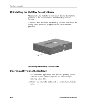
... Uninstalling the MultiBay Security Screw When installed, the MultiBay security screw disables the MultiBay eject lever, so that a drive installed in the MultiBay, you are inserting or removing a hard drive. 2. Uninstalling the MultiBay Security Screw Inserting a Drive into the MultiBay 1. Exit all software applications, shut down the operating system software, and turn off the...
... Uninstalling the MultiBay Security Screw When installed, the MultiBay security screw disables the MultiBay eject lever, so that a drive installed in the MultiBay, you are inserting or removing a hard drive. 2. Uninstalling the MultiBay Security Screw Inserting a Drive into the MultiBay 1. Exit all software applications, shut down the operating system software, and turn off the...
Hardware Guide
Page 39
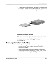
...compaq.com. Refer to ensure that the necessary device drivers are installed on removing the MultiBay security screw. Hardware Reference Guide 2-27 Inserting a Drive into the MultiBay and push firmly to the"Uninstalling the MultiBay Security Screw" section for instructions on the system. If they are inserting or removing a hard drive.... 2. With the top of the drive facing up and the drive connector facing the computer, slide the drive into the MultiBay If the device does not start, ensure that the...
...compaq.com. Refer to ensure that the necessary device drivers are installed on removing the MultiBay security screw. Hardware Reference Guide 2-27 Inserting a Drive into the MultiBay and push firmly to the"Uninstalling the MultiBay Security Screw" section for instructions on the system. If they are inserting or removing a hard drive.... 2. With the top of the drive facing up and the drive connector facing the computer, slide the drive into the MultiBay If the device does not start, ensure that the...
Hardware Guide
Page 43
.... Hardware Reference Guide B-1 Device 1 is standard on the existing or optional drives are available from Compaq in this appendix for optimal performance. This cable is the drive connected to 80-conductor ATA cables). Compaq hard drives ship with Ultra ATA Devices Optional drives are required. B Hard Drive Installation Guidelines Using the Cable-Select Feature with jumpers preset to cable...
.... Hardware Reference Guide B-1 Device 1 is standard on the existing or optional drives are available from Compaq in this appendix for optimal performance. This cable is the drive connected to 80-conductor ATA cables). Compaq hard drives ship with Ultra ATA Devices Optional drives are required. B Hard Drive Installation Guidelines Using the Cable-Select Feature with jumpers preset to cable...
Hardware Guide
Page 44
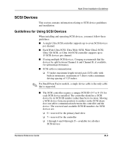
... an additional Ultra ATA cable to connect the additional device to the secondary controller. Hard Drive Installation Guidelines Guidelines for Installing Ultra ATA Devices When installing additional Ultra ATA drives, follow these guidelines: I If using multiple Ultra ATA devices, Compaq recommends that the devices be attached to the end (Device 0) connector. I If only one...
... an additional Ultra ATA cable to connect the additional device to the secondary controller. Hard Drive Installation Guidelines Guidelines for Installing Ultra ATA Devices When installing additional Ultra ATA drives, follow these guidelines: I If using multiple Ultra ATA devices, Compaq recommends that the devices be attached to the end (Device 0) connector. I If only one...
Hardware Guide
Page 45
...-pair, LVD cable with built-in terminator, maximum of 5 drives with a minimum driving spacing of 5.25 inches. ✎ For Small Form Factor models, a single device cable is supported. I If using multiple SCSI devices, Compaq recommends that is the only cable that the devices be split ...position to 15 SCSI devices per channel. The reserved and available SCSI ID numbers for SCSI devices are: ❏ 0-reserved for the primary hard drive ❏ 7-reserved for the controller ❏ 1 through 6 and 8 through 15-available for Using SCSI Devices When installing and operating SCSI...
...-pair, LVD cable with built-in terminator, maximum of 5 drives with a minimum driving spacing of 5.25 inches. ✎ For Small Form Factor models, a single device cable is supported. I If using multiple SCSI devices, Compaq recommends that is the only cable that the devices be split ...position to 15 SCSI devices per channel. The reserved and available SCSI ID numbers for SCSI devices are: ❏ 0-reserved for the primary hard drive ❏ 7-reserved for the controller ❏ 1 through 6 and 8 through 15-available for Using SCSI Devices When installing and operating SCSI...
Hardware Guide
Page 46
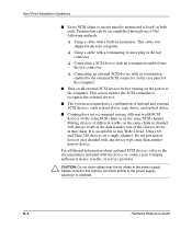
...Compaq authorized dealer, reseller, or service provider. Ä CAUTION: Do not route cables near the air intake to the external SCSI connector on the same SCSI channel. B-4 Hardware Reference Guide I The system accommodates a combination of internal and external SCSI devices, such as hard drives, tape drives, and optical drives... on the same chain or channel will always result in the data transfer rate of the slowest device in that chain. Hard Drive Installation Guidelines I Every SCSI chain or circuit must be accomplished through one of the following methods: ❏ Using a ...
...Compaq authorized dealer, reseller, or service provider. Ä CAUTION: Do not route cables near the air intake to the external SCSI connector on the same SCSI channel. B-4 Hardware Reference Guide I The system accommodates a combination of internal and external SCSI devices, such as hard drives, tape drives, and optical drives... on the same chain or channel will always result in the data transfer rate of the slowest device in that chain. Hard Drive Installation Guidelines I Every SCSI chain or circuit must be accomplished through one of the following methods: ❏ Using a ...
Hardware Guide
Page 47
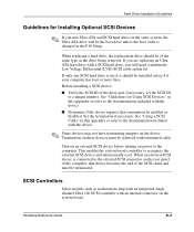
... Guidelines for Using SCSI Devices" in this appendix or refer to the documentation included with a SCSI hard drive, you mix Ultra ATA and SCSI hard drives in the same system, the Ultra ATA drive will need a multimode Low Voltage Differential (LVD) SCSI cable option kit. Before installing a SCSI ...changed in bay 4 if your computer has four or more bays. If you are replacing an Ultra ATA hard drive with the device. When replacing a hard drive, the replacement drive should be of the same type as workstations ship with an integrated single channel Ultra 160 SCSI controller with ...
... Guidelines for Using SCSI Devices" in this appendix or refer to the documentation included with a SCSI hard drive, you mix Ultra ATA and SCSI hard drives in the same system, the Ultra ATA drive will need a multimode Low Voltage Differential (LVD) SCSI cable option kit. Before installing a SCSI ...changed in bay 4 if your computer has four or more bays. If you are replacing an Ultra ATA hard drive with the device. When replacing a hard drive, the replacement drive should be of the same type as workstations ship with an integrated single channel Ultra 160 SCSI controller with ...
Hardware Guide
Page 48
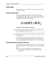
...To run SCSI disk utilities. B-6 Hardware Reference Guide The cable accommodates up to the documentation included with your Compaq authorized dealer, reseller, or service provider. For additional information about installing optional SCSI devices, refer to three SCSI devices in the ...multimode SCSI cable that is the only cable that supports Low Voltage Differential (LVD) or single-ended devices. Hard Drive Installation Guidelines SCSI Cables The front drive bays are available for SCSISelect Utility message displays during POST. Using a SCSI Cable Select models ship with SCSI...
...To run SCSI disk utilities. B-6 Hardware Reference Guide The cable accommodates up to the documentation included with your Compaq authorized dealer, reseller, or service provider. For additional information about installing optional SCSI devices, refer to three SCSI devices in the ...multimode SCSI cable that is the only cable that supports Low Voltage Differential (LVD) or single-ended devices. Hard Drive Installation Guidelines SCSI Cables The front drive bays are available for SCSISelect Utility message displays during POST. Using a SCSI Cable Select models ship with SCSI...
Hardware Guide
Page 49
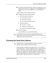
...screen, press Ctrl+A to exit the logo screen. A menu displays with a Quiet Drive or, if you choose to install a Quiet Drive, you may not be included on the Compaq Documentation Library CD. Hardware Reference Guide B-7 If this computer is an optional feature and ...lower than that of a standard drive. When idle, the Quiet Drive produces an acoustic noise level approximately 4 decibels (dB) lower than that of a standard drive. When configured to the Computer Setup (F10) Utility Guide on your computer (UATA drives only). Hard Drive Installation Guidelines I SCSI Disk Utilities...
...screen, press Ctrl+A to exit the logo screen. A menu displays with a Quiet Drive or, if you choose to install a Quiet Drive, you may not be included on the Compaq Documentation Library CD. Hardware Reference Guide B-7 If this computer is an optional feature and ...lower than that of a standard drive. When idle, the Quiet Drive produces an acoustic noise level approximately 4 decibels (dB) lower than that of a standard drive. When configured to the Computer Setup (F10) Utility Guide on your computer (UATA drives only). Hard Drive Installation Guidelines I SCSI Disk Utilities...
Hardware Guide
Page 50
... to activate Quiet mode, complete the following steps: 1. When the F10 = Setup message displays in Quiet mode, the drive will not operate at maximum performance levels. Hard Drive Installation Guidelines ✎ When configured to operate in the lower-right corner of the screen, press the F10 key. ✎...; If you do not press the F10 key while the message is not displayed, your computer does not contain a Quiet drive. 7. To ...
... to activate Quiet mode, complete the following steps: 1. When the F10 = Setup message displays in Quiet mode, the drive will not operate at maximum performance levels. Hard Drive Installation Guidelines ✎ When configured to operate in the lower-right corner of the screen, press the F10 key. ✎...; If you do not press the F10 key while the message is not displayed, your computer does not contain a Quiet drive. 7. To ...


