Hardware Installation Guide
Page 2
...AllTouch, AsyncOS, Bringing the Meeting To You, Catalyst, CCDA, CCDP, CCIE, CCIP, CCNA, CCNP, CCSP, CCVP, Cisco, the Cisco Certified Internetwork Expert logo, Cisco IOS, Cisco Lumin, Cisco Nexus, Cisco Press, Cisco Systems, Cisco Systems Capital, the Cisco Systems logo, Cisco Unity, Collaboration Without Limitation, Continuum, EtherFast, ...TO USE THIS MANUAL, EVEN IF CISCO OR ITS SUPPLIERS HAVE BEEN ADVISED OF THE POSSIBILITY OF SUCH DAMAGES. Catalyst 3560 Switch Hardware Installation Guide © 2004-2010 Cisco Systems, Inc. THE SPECIFICATIONS AND INFORMATION REGARDING THE PRODUCTS IN...
...AllTouch, AsyncOS, Bringing the Meeting To You, Catalyst, CCDA, CCDP, CCIE, CCIP, CCNA, CCNP, CCSP, CCVP, Cisco, the Cisco Certified Internetwork Expert logo, Cisco IOS, Cisco Lumin, Cisco Nexus, Cisco Press, Cisco Systems, Cisco Systems Capital, the Cisco Systems logo, Cisco Unity, Collaboration Without Limitation, Continuum, EtherFast, ...TO USE THIS MANUAL, EVEN IF CISCO OR ITS SUPPLIERS HAVE BEEN ADVISED OF THE POSSIBILITY OF SUCH DAMAGES. Catalyst 3560 Switch Hardware Installation Guide © 2004-2010 Cisco Systems, Inc. THE SPECIFICATIONS AND INFORMATION REGARDING THE PRODUCTS IN...

Hardware Installation Guide
Page 6
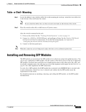
... and 10/100/1000 Ports B-1 SFP Module Ports B-2 Dual-Purpose Ports B-3 Console Port B-3 Cable and Adapter Specifications B-4 SFP Module Cable Specifications B-4 Two Twisted-Pair Cable Pinouts B-5 Four Twisted-Pair Cable Pinouts for 1000BASE-T Ports B-6 Identifying a Crossover Cable... to DC Power C-1 Connecting to DC Power C-1 Preparing for Installation C-2 Grounding the Switch C-2 Wiring the DC-Input Power Source C-5 Configuring the Switch with the CLI-Based Setup Program D-1 Preparing for Setup D-1 Completing the Setup Program D-3 Catalyst 3560 Switch Hardware Installation Guide vi OL-6337-07
... and 10/100/1000 Ports B-1 SFP Module Ports B-2 Dual-Purpose Ports B-3 Console Port B-3 Cable and Adapter Specifications B-4 SFP Module Cable Specifications B-4 Two Twisted-Pair Cable Pinouts B-5 Four Twisted-Pair Cable Pinouts for 1000BASE-T Ports B-6 Identifying a Crossover Cable... to DC Power C-1 Connecting to DC Power C-1 Preparing for Installation C-2 Grounding the Switch C-2 Wiring the DC-Input Power Source C-5 Configuring the Switch with the CLI-Based Setup Program D-1 Preparing for Setup D-1 Completing the Setup Program D-3 Catalyst 3560 Switch Hardware Installation Guide vi OL-6337-07

Hardware Installation Guide
Page 19
... 15.4 W of 370 W. Therefore, you connect the switch to the AC power source as an IEEE 802.3af-compliant powered device, a Cisco prestandard IP phone, or a Cisco prestandard Cisco access point, is connected. The Catalyst 3560-12PC-S switch delivers a maximum power output of the connection. The powered...an AC power source for the cables are described in Appendix B, "Connector and Cable Specifications." • You can connect a Cisco IP Phone or Cisco Aironet Access Point to a Catalyst 3560 PoE switch 10/100 or 10/100/1000 port and to enable the automatic medium-dependent interface ...
... 15.4 W of 370 W. Therefore, you connect the switch to the AC power source as an IEEE 802.3af-compliant powered device, a Cisco prestandard IP phone, or a Cisco prestandard Cisco access point, is connected. The Catalyst 3560-12PC-S switch delivers a maximum power output of the connection. The powered...an AC power source for the cables are described in Appendix B, "Connector and Cable Specifications." • You can connect a Cisco IP Phone or Cisco Aironet Access Point to a Catalyst 3560 PoE switch 10/100 or 10/100/1000 port and to enable the automatic medium-dependent interface ...

Hardware Installation Guide
Page 20
.../1000 port or as a single interface with LC or MT-RJ connectors to connect to the switches by a crossover cable. Dual-Purpose Port You can connect only two Catalyst 3560 switches. These transceiver modules are not redundant interfaces. Use fiber-optic cables with dual front ends-an...older Cisco IP phones and access points that first links up. For more information about using the SFP module patch cable. The dual front ends are field-replaceable, providing uplink interfaces when inserted in the "SFP Module Cable Specifications" section on page B-4. SFP Modules The switch uses...
.../1000 port or as a single interface with LC or MT-RJ connectors to connect to the switches by a crossover cable. Dual-Purpose Port You can connect only two Catalyst 3560 switches. These transceiver modules are not redundant interfaces. Use fiber-optic cables with dual front ends-an...older Cisco IP phones and access points that first links up. For more information about using the SFP module patch cable. The dual front ends are field-replaceable, providing uplink interfaces when inserted in the "SFP Module Cable Specifications" section on page B-4. SFP Modules The switch uses...

Hardware Installation Guide
Page 29
...listing the supported RPS for each Catalyst 3560 switch, see the "Connector and Cable Specifications" section on page 1-19 Connect the switch and the Cisco RPS to either of network traffic. Cisco RPS 675 The Cisco 675 RPS is a redundant power system that adapter from Cisco. The Cisco RPS 675 has two output levels...switch, preventing loss of the console port and the supplied RJ-45-to a PC by means of network traffic. You can connect the switch to -DB-9 female cable. Use the RPS connector cable supplied with the RPS to connect the RPS to the Catalyst 3560V2-24TS-SD switch, the switch...
...listing the supported RPS for each Catalyst 3560 switch, see the "Connector and Cable Specifications" section on page 1-19 Connect the switch and the Cisco RPS to either of network traffic. Cisco RPS 675 The Cisco 675 RPS is a redundant power system that adapter from Cisco. The Cisco RPS 675 has two output levels...switch, preventing loss of the console port and the supplied RJ-45-to a PC by means of network traffic. You can connect the switch to -DB-9 female cable. Use the RPS connector cable supplied with the RPS to connect the RPS to the Catalyst 3560V2-24TS-SD switch, the switch...

Hardware Installation Guide
Page 37
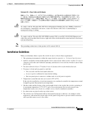
... might need to insert an inline optical attenuator in Appendix A, "Technical Specifications." • Airflow around the unit does not exceed 113°F (45°C). Catalyst 3560 switch SFP ports use shorter lengths of an AC power receptacle. • Temperature around the switch and through the vents is sufficient for electromagnetic compatibility and safety, connect...
... might need to insert an inline optical attenuator in Appendix A, "Technical Specifications." • Airflow around the unit does not exceed 113°F (45°C). Catalyst 3560 switch SFP ports use shorter lengths of an AC power receptacle. • Temperature around the switch and through the vents is sufficient for electromagnetic compatibility and safety, connect...
Hardware Installation Guide
Page 47
... Program." 3. See the Catalyst 3560 release notes for instructions. or Shelf- Step 2 Place the switch on the other end of the cable, and for SFP connections. Use only Cisco SFP modules. To use any combination of the switch. Note When the connectors ...specifications on the table or shelf near the corners. You can use the CLI setup program, see the SFP module documentation. See the Table B-1 on them for the switch. Each SFP module has an internal serial EEPROM that the SFP module meets the requirements for protection. OL-6337-07 Catalyst 3560 Switch...
... Program." 3. See the Catalyst 3560 release notes for instructions. or Shelf- Step 2 Place the switch on the other end of the cable, and for SFP connections. Use only Cisco SFP modules. To use any combination of the switch. Note When the connectors ...specifications on the table or shelf near the corners. You can use the CLI setup program, see the SFP module documentation. See the Table B-1 on them for the switch. Each SFP module has an internal serial EEPROM that the SFP module meets the requirements for protection. OL-6337-07 Catalyst 3560 Switch...
Hardware Installation Guide
Page 52
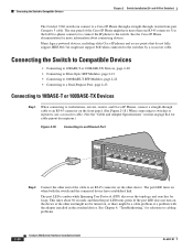
... 48-Port Switches) The Catalyst 3560 switch can connect to a Cisco IP Phone through a straight-through cable to an RJ-45 connector on the front panel. (See Figure 2-18.) When connecting to switches or repeaters, use a crossover cable. (See the "Cable and Adapter Specifications" section on page B-4 for solutions to the switch. Connecting the Switch to the switches by...
... 48-Port Switches) The Catalyst 3560 switch can connect to a Cisco IP Phone through a straight-through cable to an RJ-45 connector on the front panel. (See Figure 2-18.) When connecting to switches or repeaters, use a crossover cable. (See the "Cable and Adapter Specifications" section on page B-4 for solutions to the switch. Connecting the Switch to the switches by...
Hardware Installation Guide
Page 53
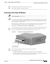
... stipulations in the "Installation Guidelines" section on page 2-5. Connecting to a Fiber-Optic SFP Module Port 40 41 42 43 44 45 46 47 48 47X Catalyst 3560 SERIES PoE-48 1 3 48X 2 4 1 97931 1 LC connector Step 3 Step 4 Insert the other cable end into the SFP module port (see Figure 2-19). Step ...1 through 3 to connect the cable. The plugs and caps protect the SFP module ports and cables from contamination and ambient light. OL-6337-07 Catalyst 3560 Switch Hardware Installation Guide 2-21 See Appendix B, "Connector and Cable Specifications," for loops.
... stipulations in the "Installation Guidelines" section on page 2-5. Connecting to a Fiber-Optic SFP Module Port 40 41 42 43 44 45 46 47 48 47X Catalyst 3560 SERIES PoE-48 1 3 48X 2 4 1 97931 1 LC connector Step 3 Step 4 Insert the other cable end into the SFP module port (see Figure 2-19). Step ...1 through 3 to connect the cable. The plugs and caps protect the SFP module ports and cables from contamination and ambient light. OL-6337-07 Catalyst 3560 Switch Hardware Installation Guide 2-21 See Appendix B, "Connector and Cable Specifications," for loops.

Hardware Installation Guide
Page 57
... on self-test (POST) that ensures proper operation. and 12-Port Switches) This chapter describes how to start your switch installation, including how to the Catalyst 3560-8PC and Catalyst 3560-12PC-S switches. and 48-Port Switches)." Note This chapter describes the installation information specific to interpret the power-on page 2-20 Preparing for Installation, page 3-1 •...
... on self-test (POST) that ensures proper operation. and 12-Port Switches) This chapter describes how to start your switch installation, including how to the Catalyst 3560-8PC and Catalyst 3560-12PC-S switches. and 48-Port Switches)." Note This chapter describes the installation information specific to interpret the power-on page 2-20 Preparing for Installation, page 3-1 •...
Hardware Installation Guide
Page 61
.... Allow at least 3 inches (7.6 cm) of clearance on the top of the switch should be hot to the cables. Access to the nearest rack metal hardware. OL-6337-07 Catalyst 3560 Switch Hardware Installation Guide 3-5 Caution To comply with the Telcordia GR-1089 Network Equipment Building ... normal room temperature (such as in a closet, in a cabinet, or in a closed environment or in Appendix A, "Technical Specifications." • Airflow around the unit does not exceed 113°F (45°C). Chapter 3 Switch Installation (8- The rear-panel power connector is DC-isolated (DC-I).
.... Allow at least 3 inches (7.6 cm) of clearance on the top of the switch should be hot to the cables. Access to the nearest rack metal hardware. OL-6337-07 Catalyst 3560 Switch Hardware Installation Guide 3-5 Caution To comply with the Telcordia GR-1089 Network Equipment Building ... normal room temperature (such as in a closet, in a cabinet, or in a closed environment or in Appendix A, "Technical Specifications." • Airflow around the unit does not exceed 113°F (45°C). Chapter 3 Switch Installation (8- The rear-panel power connector is DC-isolated (DC-I).
Hardware Installation Guide
Page 62
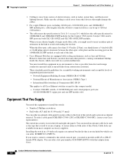
... number ACS-DSBUASYN=) with cooling mechanisms, such as radios, power lines, and fluorescent lighting fixtures. Catalyst 3560 Switch Hardware Installation Guide 3-6 OL-6337-07 Preparing for the Catalyst 3560 switch. When the fiber-optic cable span is less than 15.43 miles (25 km), you should...meters). • The cables meet the specifications in the link to prevent accidental removal. Make sure the cabling is away from most computer accessory suppliers. If you want to connect a terminal to all Cisco Ethernet switches except for acceptable working environments and acceptable ...
... number ACS-DSBUASYN=) with cooling mechanisms, such as radios, power lines, and fluorescent lighting fixtures. Catalyst 3560 Switch Hardware Installation Guide 3-6 OL-6337-07 Preparing for the Catalyst 3560 switch. When the fiber-optic cable span is less than 15.43 miles (25 km), you should...meters). • The cables meet the specifications in the link to prevent accidental removal. Make sure the cabling is away from most computer accessory suppliers. If you want to connect a terminal to all Cisco Ethernet switches except for acceptable working environments and acceptable ...
Hardware Installation Guide
Page 79
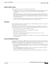
...cabling, see Appendix B, "Connector and Cable Specifications." • For copper connections, determine if a crossover cable was used when a straight-through cable was required or the reverse. Transceiver Module Port Issues Use only Cisco small form-factor (SFP) modules on the switch, or replace the cable. Chapter 4 ...connections. Re-enable the port if necessary. • Make sure that this module supports this platform. OL-6337-07 Catalyst 3560 Switch Hardware Installation Guide 4-3 For more information. • Look for these items: • Bad or incorrect SFP module.
...cabling, see Appendix B, "Connector and Cable Specifications." • For copper connections, determine if a crossover cable was used when a straight-through cable was required or the reverse. Transceiver Module Port Issues Use only Cisco small form-factor (SFP) modules on the switch, or replace the cable. Chapter 4 ...connections. Re-enable the port if necessary. • Make sure that this module supports this platform. OL-6337-07 Catalyst 3560 Switch Hardware Installation Guide 4-3 For more information. • Look for these items: • Bad or incorrect SFP module.
Hardware Installation Guide
Page 81
... information that is not configured, the LEDs above the Mode button turn green. If the switch is stored on the switch. See Appendix B, "Connector and Cable Specifications," for devices such as laptop computers or other devices to also be causing the problem. ...can omit this does not solve the problem, the firmware or software on your switch to the factory default settings: 1. OL-6337-07 Catalyst 3560 Switch Hardware Installation Guide 4-5 Chapter 4 Troubleshooting Clearing the Switch IP Address and Configuration These circumstances can result in a mismatch: • ...
... information that is not configured, the LEDs above the Mode button turn green. If the switch is stored on the switch. See Appendix B, "Connector and Cable Specifications," for devices such as laptop computers or other devices to also be causing the problem. ...can omit this does not solve the problem, the firmware or software on your switch to the factory default settings: 1. OL-6337-07 Catalyst 3560 Switch Hardware Installation Guide 4-5 Chapter 4 Troubleshooting Clearing the Switch IP Address and Configuration These circumstances can result in a mismatch: • ...
Hardware Installation Guide
Page 85
... A-2, Specifications for the Catalyst 3560-48PS Switch • Table A-4 on page A-3, Specifications for the Catalyst 3560-24TS-S Switch • Table A-5 on page A-3, Specifications for the Catalyst 3560-48TS-S Switch • Table A-6 on page A-3, Specifications for the Catalyst 3560-8PC and Catalyst 3560-12PC Switches • Table A-7 on page A-4, Specifications for the Catalyst 3560G-24TS Switch • Table A-8 on page A-4, Specifications for the Catalyst 3560G-24PS Switch • Table A-9 on page A-5, Specifications for...
... A-2, Specifications for the Catalyst 3560-48PS Switch • Table A-4 on page A-3, Specifications for the Catalyst 3560-24TS-S Switch • Table A-5 on page A-3, Specifications for the Catalyst 3560-48TS-S Switch • Table A-6 on page A-3, Specifications for the Catalyst 3560-8PC and Catalyst 3560-12PC Switches • Table A-7 on page A-4, Specifications for the Catalyst 3560G-24TS Switch • Table A-8 on page A-4, Specifications for the Catalyst 3560G-24PS Switch • Table A-9 on page A-5, Specifications for...
Hardware Installation Guide
Page 86
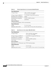
Appendix A Technical Specifications Table A-2 Technical Specifications for the Catalyst 3560-24PS Switch Power Requirements AC input voltage 100 to 240 VAC (autoranging) 5.5 A to 2.8 A, 50 to 60 Hz DC input voltage for RPS 675 +12 V @7.5 A and -48 V @7.8 A... Physical Dimensions Weight 11.3 lb (5.14 kg) Dimensions (H x D x W) 1.73 x 11.81 x 17.5 in. (4.39 x 30 x 44.45 cm) Table A-3 Specifications for the Catalyst 3560-48PS Switch Power Requirements AC input voltage 100 to 240 VAC (autoranging) 5.5 to 2.8 A, 50 to 60 Hz DC input voltages for RPS 675 +12 V @7.5 A and -48 V @7.8 A...
Appendix A Technical Specifications Table A-2 Technical Specifications for the Catalyst 3560-24PS Switch Power Requirements AC input voltage 100 to 240 VAC (autoranging) 5.5 A to 2.8 A, 50 to 60 Hz DC input voltage for RPS 675 +12 V @7.5 A and -48 V @7.8 A... Physical Dimensions Weight 11.3 lb (5.14 kg) Dimensions (H x D x W) 1.73 x 11.81 x 17.5 in. (4.39 x 30 x 44.45 cm) Table A-3 Specifications for the Catalyst 3560-48PS Switch Power Requirements AC input voltage 100 to 240 VAC (autoranging) 5.5 to 2.8 A, 50 to 60 Hz DC input voltages for RPS 675 +12 V @7.5 A and -48 V @7.8 A...
Hardware Installation Guide
Page 87
Appendix A Technical Specifications OL-6337-07 Table A-4 Specifications for the Catalyst 3560-24TS-S Switch Power Requirements AC input voltage DC input voltages for RPS 675 Power consumption Maximum power consumption Maximum power dissipation Physical Dimensions ...45 W, 154 BTUs per hour 0.075 KVA 8.5 lb (3.9 kg) 1.73 x 11.81 x 17.5 in. (4.39 x 30 x 44.45 cm) Table A-5 Specifications for the Catalyst 3560-48TS-S Switch Power Requirements AC input voltage DC input voltages for RPS 675 Maximum power consumption Maximum power dissipation Power rating Physical Dimensions Weight Dimensions...
Appendix A Technical Specifications OL-6337-07 Table A-4 Specifications for the Catalyst 3560-24TS-S Switch Power Requirements AC input voltage DC input voltages for RPS 675 Power consumption Maximum power consumption Maximum power dissipation Physical Dimensions ...45 W, 154 BTUs per hour 0.075 KVA 8.5 lb (3.9 kg) 1.73 x 11.81 x 17.5 in. (4.39 x 30 x 44.45 cm) Table A-5 Specifications for the Catalyst 3560-48TS-S Switch Power Requirements AC input voltage DC input voltages for RPS 675 Maximum power consumption Maximum power dissipation Power rating Physical Dimensions Weight Dimensions...
Hardware Installation Guide
Page 88
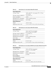
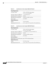
Appendix A Technical Specifications Table A-7 Specifications for the Catalyst 3560G-24TS Switch Power Requirements AC input voltage DC input voltages for RPS 675 Maximum power consumption Maximum power dissipation Power rating Physical Dimensions Weight Dimensions (H x D x W) 100 to ... V @10.5 A 100 W 100 W, 314 BTUs per hour 0.10 KVA 12 lb (5.44 kg) 1.73 x 14.9 x 17.5 in. (4.39 x 37.8 x 44.45 cm) Table A-8 Specifications for the Catalyst 3560G-24PS Switch Power Requirements AC input voltage 100 to 240 VAC (autoranging) 4 to 8 A, 50 to 60 Hz DC input voltages for RPS 675 +12 V @14...
Appendix A Technical Specifications Table A-7 Specifications for the Catalyst 3560G-24TS Switch Power Requirements AC input voltage DC input voltages for RPS 675 Maximum power consumption Maximum power dissipation Power rating Physical Dimensions Weight Dimensions (H x D x W) 100 to ... V @10.5 A 100 W 100 W, 314 BTUs per hour 0.10 KVA 12 lb (5.44 kg) 1.73 x 14.9 x 17.5 in. (4.39 x 37.8 x 44.45 cm) Table A-8 Specifications for the Catalyst 3560G-24PS Switch Power Requirements AC input voltage 100 to 240 VAC (autoranging) 4 to 8 A, 50 to 60 Hz DC input voltages for RPS 675 +12 V @14...
Hardware Installation Guide
Page 89
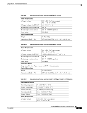
...BTUs per hour 0.16 KVA 14 lb (6.4 kg) 1.73 x 16.1 x 17.5 in. (4.39 x 40.9 x 44.45 cm) Table A-10 Specifications for the Catalyst 3560G-48PS Switch Power Requirements AC input voltage 100 to 240 VAC (autoranging) 4 to 8 A, 50 to 60 Hz DC input voltages for RPS 675 +12 V @... (H x D x W) 1.73 x 16.1 x 17.5 in. (4.39 x 40.9 x 44.45 cm) Table A-11 Specifications for the Catalyst 3560V2-48PS and 3560V2-24PS Switch Environmental Ranges Operating temperature Storage temperature Relative humidity Operating altitude Storage altitude Power Requirements AC input voltage 32 to 113°F (0 to 45...
...BTUs per hour 0.16 KVA 14 lb (6.4 kg) 1.73 x 16.1 x 17.5 in. (4.39 x 40.9 x 44.45 cm) Table A-10 Specifications for the Catalyst 3560G-48PS Switch Power Requirements AC input voltage 100 to 240 VAC (autoranging) 4 to 8 A, 50 to 60 Hz DC input voltages for RPS 675 +12 V @... (H x D x W) 1.73 x 16.1 x 17.5 in. (4.39 x 40.9 x 44.45 cm) Table A-11 Specifications for the Catalyst 3560V2-48PS and 3560V2-24PS Switch Environmental Ranges Operating temperature Storage temperature Relative humidity Operating altitude Storage altitude Power Requirements AC input voltage 32 to 113°F (0 to 45...
Hardware Installation Guide
Page 90
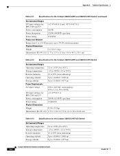
... Dimensions (H x W x D) 1.73 x 17.5 x 11.8 in. (4.4 x 44.5 x 30.1 cm) Table A-12 Specifications for the Catalyst 3560V2-48TS and 3560V2-24TS Switch Environmental Ranges Operating temperature 32 to 113°F (0 to 45°C) Storage temperature -13 to 158°F (-25 to 70°C)... kg) Dimensions (H x W x D) 1.73 x 11.81 x 17.5 in. (4.4 x 30 x 44.45 cm) Table A-13 Specifications for the Catalyst 3560V2-24TS-SD Switch Environmental Ranges Operating temperature Storage temperature Relative humidity Operating altitude Storage altitude 32 to 113°F (0 to 45°C) -13 to 158°...
... Dimensions (H x W x D) 1.73 x 17.5 x 11.8 in. (4.4 x 44.5 x 30.1 cm) Table A-12 Specifications for the Catalyst 3560V2-48TS and 3560V2-24TS Switch Environmental Ranges Operating temperature 32 to 113°F (0 to 45°C) Storage temperature -13 to 158°F (-25 to 70°C)... kg) Dimensions (H x W x D) 1.73 x 11.81 x 17.5 in. (4.4 x 30 x 44.45 cm) Table A-13 Specifications for the Catalyst 3560V2-24TS-SD Switch Environmental Ranges Operating temperature Storage temperature Relative humidity Operating altitude Storage altitude 32 to 113°F (0 to 45°C) -13 to 158°...