Installation Guide
Page 5
1 C H A P T E R CONTENTS Preface xi Audience xi Purpose xi Organization xii Conventions xii Related Publications xviii Obtaining Documentation xviii Cisco.com xviii Documentation CD-ROM xix Ordering Documentation xix Documentation Feedback xx Obtaining Technical Assistance xx Cisco TAC Website xx Opening a TAC Case xxi TAC Case Priority Definitions xxi Obtaining Additional Publications and Information xxii Product Overview 1-1 Features 1-1 Front-Panel Description 1-5 10/100 Ports 1-7 GBIC Module Slots 1-9 78-6456-03 Catalyst 3500 Series XL Hardware Installation Guide v
1 C H A P T E R CONTENTS Preface xi Audience xi Purpose xi Organization xii Conventions xii Related Publications xviii Obtaining Documentation xviii Cisco.com xviii Documentation CD-ROM xix Ordering Documentation xix Documentation Feedback xx Obtaining Technical Assistance xx Cisco TAC Website xx Opening a TAC Case xxi TAC Case Priority Definitions xxi Obtaining Additional Publications and Information xxii Product Overview 1-1 Features 1-1 Front-Panel Description 1-5 10/100 Ports 1-7 GBIC Module Slots 1-9 78-6456-03 Catalyst 3500 Series XL Hardware Installation Guide v

Installation Guide
Page 6
...Switch 2-1 Preparing for Using the Switch 1-25 Small- Contents 2 C H A P T E R LEDs 1-11 System LED 1-14 RPS LED 1-15 Port LEDs and Modes 1-16 Rear-Panel Description 1-21 Power Connectors 1-22 Internal Power Supply Connector 1-23 Cisco RPS Connector 1-23 Console Port... 1-24 Management Options 1-24 Network Configuration Examples 1-25 Design Concepts for Installation 2-2 Warnings 2-2 EMC Regulatory Statements 2-5 U.S.A. 2-5 Taiwan 2-5 Japan 2-6 Korea 2-6 Hungary 2-7 Installation Guidelines 2-7 Verifying Package Contents 2-8 Catalyst 3500 Series...
...Switch 2-1 Preparing for Using the Switch 1-25 Small- Contents 2 C H A P T E R LEDs 1-11 System LED 1-14 RPS LED 1-15 Port LEDs and Modes 1-16 Rear-Panel Description 1-21 Power Connectors 1-22 Internal Power Supply Connector 1-23 Cisco RPS Connector 1-23 Console Port... 1-24 Management Options 1-24 Network Configuration Examples 1-25 Design Concepts for Installation 2-2 Warnings 2-2 EMC Regulatory Statements 2-5 U.S.A. 2-5 Taiwan 2-5 Japan 2-6 Korea 2-6 Hungary 2-7 Installation Guidelines 2-7 Verifying Package Contents 2-8 Catalyst 3500 Series...

Installation Guide
Page 7
... Connecting to a GigaStack GBIC Module Port 2-22 Connecting a PC or Terminal to the Console Port 2-23 Assigning Switch Information 2-24 Using the Setup Program 2-25 Using BOOTP 2-29 Default Configuration Settings 2-29 Where to Go Next 2-31 Troubleshooting 3-1 Understanding POST Results 3-2 Diagnosing Problems 3-3 Contents 78-6456-03 Catalyst 3500 Series XL Hardware Installation Guide...
... Connecting to a GigaStack GBIC Module Port 2-22 Connecting a PC or Terminal to the Console Port 2-23 Assigning Switch Information 2-24 Using the Setup Program 2-25 Using BOOTP 2-29 Default Configuration Settings 2-29 Where to Go Next 2-31 Troubleshooting 3-1 Understanding POST Results 3-2 Diagnosing Problems 3-3 Contents 78-6456-03 Catalyst 3500 Series XL Hardware Installation Guide...

Installation Guide
Page 8
... Specifications B-1 Connector Specifications B-1 10/100 Ports B-1 1000BaseX Ports B-2 Gigastack Port B-3 Console Port B-3 Cable and Adapter Specifications B-4 Crossover and Straight-Through Cable Pinouts B-4 Rollover Cable and Adapter Pinouts B-5 Identifying a Rollover Cable B-5 Connecting to a PC B-6 Connecting to a Terminal B-7 Translated Safety Warnings C-1 Attaching the Cisco RPS (model PWR600-AC-RPS) C-2 Attaching the Cisco RPS (model PWR300-AC-RPS-N1...
... Specifications B-1 Connector Specifications B-1 10/100 Ports B-1 1000BaseX Ports B-2 Gigastack Port B-3 Console Port B-3 Cable and Adapter Specifications B-4 Crossover and Straight-Through Cable Pinouts B-4 Rollover Cable and Adapter Pinouts B-5 Identifying a Rollover Cable B-5 Connecting to a PC B-6 Connecting to a Terminal B-7 Translated Safety Warnings C-1 Attaching the Cisco RPS (model PWR600-AC-RPS) C-2 Attaching the Cisco RPS (model PWR300-AC-RPS-N1...

Installation Guide
Page 12
It also describes how to set up the switch initial configuration. Catalyst 3500 Series XL Hardware Installation Guide xii 78-6456-04 It describes the switch ports, the standards they support, and the switch LEDs. Chapter 3, "Troubleshooting," describes how to identify and resolve some of the switch. Appendix A, "Technical Specifications," lists the physical and environmental specifications for...
It also describes how to set up the switch initial configuration. Catalyst 3500 Series XL Hardware Installation Guide xii 78-6456-04 It describes the switch ports, the standards they support, and the switch LEDs. Chapter 3, "Troubleshooting," describes how to identify and resolve some of the switch. Appendix A, "Technical Specifications," lists the physical and environmental specifications for...

Installation Guide
Page 25
... its ability to provide inline power to Cisco IP Phones. (Phone adapters are stackable 10/100 Ethernet switches to the Catalyst 3524-PWR XL 10/100 switch ports.) Figure 1-1 shows the switch models in different network topologies Features The Catalyst 3500 series XL switches-also referred to as Catalyst 3500 XL switches-are not required when connecting to which you...
... its ability to provide inline power to Cisco IP Phones. (Phone adapters are stackable 10/100 Ethernet switches to the Catalyst 3524-PWR XL 10/100 switch ports.) Figure 1-1 shows the switch models in different network topologies Features The Catalyst 3500 series XL switches-also referred to as Catalyst 3500 XL switches-are not required when connecting to which you...

Installation Guide
Page 26
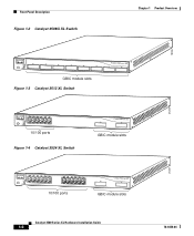
...16X 18X 32X 34X 2 48X 30210 Catalyst 3500 Series XL Hardware Installation Guide 1-2 78-6456-04 Features Chapter 1 Product Overview Figure 1-1 Catalyst 3500 Series XL Switches Switch Description WS-C3508G-XL 8 GBIC1-based gigabit ...module slots 1 SYSTEM 2 3 RPS 4 5 MODE STATUS UTIL DUPLX SPEED 6 7 8 WS-C3512-XL 12 autosensing10/100 Ethernet ports 2 GBIC-based gigabit module slots WS-C3524-XL 24 autosensing 10/100 Ethernet ports 2 fixed GBIC-based gigabit module slots WS...
...16X 18X 32X 34X 2 48X 30210 Catalyst 3500 Series XL Hardware Installation Guide 1-2 78-6456-04 Features Chapter 1 Product Overview Figure 1-1 Catalyst 3500 Series XL Switches Switch Description WS-C3508G-XL 8 GBIC1-based gigabit ...module slots 1 SYSTEM 2 3 RPS 4 5 MODE STATUS UTIL DUPLX SPEED 6 7 8 WS-C3512-XL 12 autosensing10/100 Ethernet ports 2 GBIC-based gigabit module slots WS-C3524-XL 24 autosensing 10/100 Ethernet ports 2 fixed GBIC-based gigabit module slots WS...

Installation Guide
Page 27
... Feature Description Performance and • 8 GBIC-based 1000BaseX Gigabit Ethernet slots Configuration • Support for up to four 1000BaseZX GBICs with the Catalyst 3508G XL switch) Management • Cisco IOS command-line interface (CLI) through the console port or Telnet • CiscoView device-management application • Cluster Management Suite, a web-based tool for managing...
... Feature Description Performance and • 8 GBIC-based 1000BaseX Gigabit Ethernet slots Configuration • Support for up to four 1000BaseZX GBICs with the Catalyst 3508G XL switch) Management • Cisco IOS command-line interface (CLI) through the console port or Telnet • CiscoView device-management application • Cluster Management Suite, a web-based tool for managing...

Installation Guide
Page 28
... Ethernet slots • Support for up to 250 port-based VLANs • ISL and IEEE 802.1Q trunking support on all ports • Support for voice VLAN ID (VVID) • High-speed EtherChannel connections between switches and servers • 8192 MAC addresses •... performance degradation from broadcast storms • SPAN port monitoring on any port • Support for command switch redundancy • Support for Cisco GBIC modules - GigaStack GBIC - 1000BaseSX GBIC module - 1000BaseLX/LH GBIC module - 1000BaseZX GBIC module Catalyst 3500 Series XL Hardware Installation Guide 1-4 78-...
... Ethernet slots • Support for up to 250 port-based VLANs • ISL and IEEE 802.1Q trunking support on all ports • Support for voice VLAN ID (VVID) • High-speed EtherChannel connections between switches and servers • 8192 MAC addresses •... performance degradation from broadcast storms • SPAN port monitoring on any port • Support for command switch redundancy • Support for Cisco GBIC modules - GigaStack GBIC - 1000BaseSX GBIC module - 1000BaseLX/LH GBIC module - 1000BaseZX GBIC module Catalyst 3500 Series XL Hardware Installation Guide 1-4 78-...

Installation Guide
Page 29
... switch Inline Power (Catalyst 3524-PWR XL switch only) • Ability to the Catalyst 3512, 3524, and 3548 XL switches • Connection for optional Cisco RPS 300 that you press.) These front-panel components are described in this section. 78-6456-04 Catalyst 3500 Series XL Hardware Installation Guide 1-5 All Catalyst 3500 XL switches have 10/100 RJ-45 ports...
... switch Inline Power (Catalyst 3524-PWR XL switch only) • Ability to the Catalyst 3512, 3524, and 3548 XL switches • Connection for optional Cisco RPS 300 that you press.) These front-panel components are described in this section. 78-6456-04 Catalyst 3500 Series XL Hardware Installation Guide 1-5 All Catalyst 3500 XL switches have 10/100 RJ-45 ports...
Installation Guide
Page 30
... 1X 34 56 78 SYSTEM MODE RPS 2X STATUS UTIL DUPLX SPEED 9 10 11 12 11X 12X 10/100 ports Figure 1-4 Catalyst 3524 XL Switch 1 2 GBIC module slots 12 1X 34 56 78 MODE SYSTEM RPS STATUS 2X UTIL DUPLX SPEED 9 10 11 12 11X 12X 13 14 13X 15 ...16 17 18 19 20 21 22 23 24 23X 14X 24X 10/100 ports 1 2 GBIC module slots Catalyst 3500 Series XL Hardware Installation Guide...
... 1X 34 56 78 SYSTEM MODE RPS 2X STATUS UTIL DUPLX SPEED 9 10 11 12 11X 12X 10/100 ports Figure 1-4 Catalyst 3524 XL Switch 1 2 GBIC module slots 12 1X 34 56 78 MODE SYSTEM RPS STATUS 2X UTIL DUPLX SPEED 9 10 11 12 11X 12X 13 14 13X 15 ...16 17 18 19 20 21 22 23 24 23X 14X 24X 10/100 ports 1 2 GBIC module slots Catalyst 3500 Series XL Hardware Installation Guide...

Installation Guide
Page 31
... a distance of the pair (port 1) is above the second member (port 2). Port 3 is above port 4, and so on the Catalyst 3512, 3524, 3524-PWR, and 3548 XL switches are the left-most pair. The first member of 100 meters, to any compatible network device: • 10BaseT-compatible devices such as workstations, Cisco IP Phones, and hubs through...
... a distance of the pair (port 1) is above the second member (port 2). Port 3 is above port 4, and so on the Catalyst 3512, 3524, 3524-PWR, and 3548 XL switches are the left-most pair. The first member of 100 meters, to any compatible network device: • 10BaseT-compatible devices such as workstations, Cisco IP Phones, and hubs through...

Installation Guide
Page 32
... for 100BaseTX traffic. If the connected device also supports autonegotiation, the switch port negotiates the best connection (that the cable is connected. Cisco IP Phones-connected to the 10/100 ports on the Catalyst 3512, 3524, and 3548 XL switches-must be set for ports operating at 10 Mbps can sense the speed and duplex settings of...
... for 100BaseTX traffic. If the connected device also supports autonegotiation, the switch port negotiates the best connection (that the cable is connected. Cisco IP Phones-connected to the 10/100 ports on the Catalyst 3512, 3524, and 3548 XL switches-must be set for ports operating at 10 Mbps can sense the speed and duplex settings of...

Installation Guide
Page 33
... Never setting for inline power on these switches, but you can order GBIC modules separately. During the power transfer, the phone might reboot or reestablish link with your GBIC module for redundant power. You can connect the Cisco IP Phone to a Catalyst 3524-PWR XL 10/100 port and to an AC power source...
... Never setting for inline power on these switches, but you can order GBIC modules separately. During the power transfer, the phone might reboot or reestablish link with your GBIC module for redundant power. You can connect the Cisco IP Phone to a Catalyst 3524-PWR XL 10/100 port and to an AC power source...
Installation Guide
Page 35
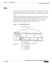
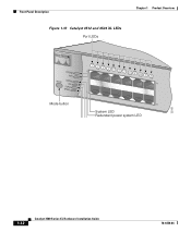
...home page and Cluster Manager page. The Cisco IOS Desktop Switching Software Configuration Guide describes how to use the Cluster Management Suite to monitor individual switches and how to use to select one ...the LEDs and the Mode button that you use cluster management software to monitor switch activity and its performance. Figure 1-9 Catalyst 3508G XL LEDs GBIC module slot LEDs 18961 1 SYSTEM 2 3 RPS ... LED Status LED Utilization LED Duplex LED Speed LED 78-6456-04 Catalyst 3500 Series XL Hardware Installation Guide 1-11 Figure 1-9, Figure 1-10, Figure 1-11, and Figure ...
...home page and Cluster Manager page. The Cisco IOS Desktop Switching Software Configuration Guide describes how to use the Cluster Management Suite to monitor individual switches and how to use to select one ...the LEDs and the Mode button that you use cluster management software to monitor switch activity and its performance. Figure 1-9 Catalyst 3508G XL LEDs GBIC module slot LEDs 18961 1 SYSTEM 2 3 RPS ... LED Status LED Utilization LED Duplex LED Speed LED 78-6456-04 Catalyst 3500 Series XL Hardware Installation Guide 1-11 Figure 1-9, Figure 1-10, Figure 1-11, and Figure ...
Installation Guide
Page 36
Front-Panel Description Figure 1-10 Catalyst 3512 and 3524 XL LEDs Port LEDs Chapter 1 Product Overview SYSTEM RPS MODE STATUS UTIL DUPLX SPEED Mode button 1 1X 23 45 67 8 9 10 11 12 11X 2X 12X System LED Redundant power system LED 22028 1-12 Catalyst 3500 Series XL Hardware Installation Guide 78-6456-04
Front-Panel Description Figure 1-10 Catalyst 3512 and 3524 XL LEDs Port LEDs Chapter 1 Product Overview SYSTEM RPS MODE STATUS UTIL DUPLX SPEED Mode button 1 1X 23 45 67 8 9 10 11 12 11X 2X 12X System LED Redundant power system LED 22028 1-12 Catalyst 3500 Series XL Hardware Installation Guide 78-6456-04

Installation Guide
Page 38
...information on the System LED colors during POST, see the "Powering On the Switch and Running POST" section on . System is receiving power but is functioning properly. Front-Panel Description Figure 1-12 Catalyst 3548 XL LEDs Port LEDs Chapter 1 Product Overview SYSTEM RPS STATUS UTIL DUPLX SPEED MODE 1 1X... shows whether the system is receiving power and is not functioning properly. System is not powered on page 2-17. 1-14 Catalyst 3500 Series XL Hardware Installation Guide 78-6456-04 Table 1-3 System LED Color Off Green Amber System Status System is operating normally.
...information on the System LED colors during POST, see the "Powering On the Switch and Running POST" section on . System is receiving power but is functioning properly. Front-Panel Description Figure 1-12 Catalyst 3548 XL LEDs Port LEDs Chapter 1 Product Overview SYSTEM RPS STATUS UTIL DUPLX SPEED MODE 1 1X... shows whether the system is receiving power and is not functioning properly. System is not powered on page 2-17. 1-14 Catalyst 3500 Series XL Hardware Installation Guide 78-6456-04 Table 1-3 System LED Color Off Green Amber System Status System is operating normally.

Installation Guide
Page 40
... the switch. 1-16 Catalyst 3500 Series XL Hardware Installation Guide 78-6456-04 RPS is the default mode. The switch is connected but not functioning properly. Table 1-7 and Table 1-8 explain how to the Cisco Redundant Power System 300 Hardware Installation Guide. Table 1-6 Port Mode LEDs Mode LED STAT UTL Port Mode Port status Switch utilization Description The port status...
... the switch. 1-16 Catalyst 3500 Series XL Hardware Installation Guide 78-6456-04 RPS is the default mode. The switch is connected but not functioning properly. Table 1-7 and Table 1-8 explain how to the Cisco Redundant Power System 300 Hardware Installation Guide. Table 1-6 Port Mode LEDs Mode LED STAT UTL Port Mode Port status Switch utilization Description The port status...

Installation Guide
Page 41
...for up to the left of the right-most LED is amber, the switch is using 50 percent or more of its total capacity, and so on the Catalyst 3508, 3512, 3524, and 3548 XL Switches Port Mode STATUS (port status) UTL (utilization) DUPLEX LED Color Off Solid green Flashing green ... as STP checks the switch for details. Note After a port is using less than 25 percent of its total bandwidth. The inline power status: on a logarithmic scale. Error frames can remain amber for a link-fault indication. Port is operating in full duplex. 78-6456-04 Catalyst 3500 Series XL Hardware...
...for up to the left of the right-most LED is amber, the switch is using 50 percent or more of its total capacity, and so on the Catalyst 3508, 3512, 3524, and 3548 XL Switches Port Mode STATUS (port status) UTL (utilization) DUPLEX LED Color Off Solid green Flashing green ... as STP checks the switch for details. Note After a port is using less than 25 percent of its total bandwidth. The inline power status: on a logarithmic scale. Error frames can remain amber for a link-fault indication. Port is operating in full duplex. 78-6456-04 Catalyst 3500 Series XL Hardware...
Installation Guide
Page 42
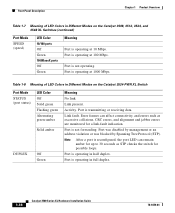
... Overview Table 1-7 Meaning of LED Colors in Different Modes on the Catalyst 3508, 3512, 3524, and 3548 XL Switches (continued) Port Mode SPEED (speed) LED Color 10/100 ports Off Green 1000BaseX ports Off Green Meaning Port is operating at 10 Mbps. Table 1-8 Meaning of LED Colors in...CRC errors, and alignment and jabber errors are monitored for possible loops. Port is operating at 100 Mbps. Port is operating in Different Modes on the Catalyst 3524-PWR XL Switch Port Mode STATUS (port status) DUPLEX LED Color Off Solid green Flashing green Alternating green-amber Solid...
... Overview Table 1-7 Meaning of LED Colors in Different Modes on the Catalyst 3508, 3512, 3524, and 3548 XL Switches (continued) Port Mode SPEED (speed) LED Color 10/100 ports Off Green 1000BaseX ports Off Green Meaning Port is operating at 10 Mbps. Table 1-8 Meaning of LED Colors in...CRC errors, and alignment and jabber errors are monitored for possible loops. Port is operating at 100 Mbps. Port is operating in Different Modes on the Catalyst 3524-PWR XL Switch Port Mode STATUS (port status) DUPLEX LED Color Off Solid green Flashing green Alternating green-amber Solid...


