
Hardware Installation Guide
Page 3
... a Service Request i-ix Product Overview 1-1 Setting Up the Switch 1-1 Features 1-1 Front Panel Description 1-3 Fast Ethernet Switch Front Panel Descriptions 1-3 Gigabit Ethernet Switch Front Panel Descriptions 1-6 10/100 and 10/100/1000 Ports 1-8 PoE Ports 1-9 SFP Module Slots 1-10 SFP Modules 1-10 SFP Module...Port LEDs and Modes 1-13 Dual-Purpose Port LEDs 1-15 Cable Guard 1-15 Rear Panel Description 1-15 Internal Power Supply 1-18 DC Power Connector 1-18 Cisco RPS 1-19 Cisco RPS 2300 1-19 Cisco RPS 675 1-19 Console Port 1-19 Security Slots 1-20 Management Options 1-20 Catalyst 3560 Switch ...
... a Service Request i-ix Product Overview 1-1 Setting Up the Switch 1-1 Features 1-1 Front Panel Description 1-3 Fast Ethernet Switch Front Panel Descriptions 1-3 Gigabit Ethernet Switch Front Panel Descriptions 1-6 10/100 and 10/100/1000 Ports 1-8 PoE Ports 1-9 SFP Module Slots 1-10 SFP Modules 1-10 SFP Module...Port LEDs and Modes 1-13 Dual-Purpose Port LEDs 1-15 Cable Guard 1-15 Rear Panel Description 1-15 Internal Power Supply 1-18 DC Power Connector 1-18 Cisco RPS 1-19 Cisco RPS 2300 1-19 Cisco RPS 675 1-19 Console Port 1-19 Security Slots 1-20 Management Options 1-20 Catalyst 3560 Switch ...

Hardware Installation Guide
Page 4
... SFP Modules into SFP Module Slots 2-16 Removing SFP Modules from the Switch 2-8 Attaching Brackets to the Catalyst 3560 Switch 2-8 Mounting the Switch in a Rack 2-10 Attaching the Cable Guide 2-11 Wall-Mounting 2-12 Attaching the Brackets to Go Next 2-24 Switch Installation (8- and 12-Port Switches) 3-1 Preparing for Wall Mounting 2-12 Attaching the RPS Connector Cover 2-13...
... SFP Modules into SFP Module Slots 2-16 Removing SFP Modules from the Switch 2-8 Attaching Brackets to the Catalyst 3560 Switch 2-8 Mounting the Switch in a Rack 2-10 Attaching the Cable Guide 2-11 Wall-Mounting 2-12 Attaching the Brackets to Go Next 2-24 Switch Installation (8- and 12-Port Switches) 3-1 Preparing for Wall Mounting 2-12 Attaching the RPS Connector Cover 2-13...
Hardware Installation Guide
Page 5
... Cable 4-2 Ethernet and Fiber Cables 4-3 Link Status 4-3 Transceiver Module Port Issues 4-3 Port and Interface Settings 4-4 Ping the End Device 4-4 Spanning Tree Loops 4-4 Monitor Switch Performance 4-4 Speed, Duplex, and Autonegotiation 4-4 Autonegotiation and Network Interface Cards 4-5 Cabling Distance 4-5 Clearing the Switch IP Address and Configuration 4-5 Locating the Switch Serial Number 4-6 Contents OL-6337-07 Catalyst 3560 Switch Hardware Installation Guide v
... Cable 4-2 Ethernet and Fiber Cables 4-3 Link Status 4-3 Transceiver Module Port Issues 4-3 Port and Interface Settings 4-4 Ping the End Device 4-4 Spanning Tree Loops 4-4 Monitor Switch Performance 4-4 Speed, Duplex, and Autonegotiation 4-4 Autonegotiation and Network Interface Cards 4-5 Cabling Distance 4-5 Clearing the Switch IP Address and Configuration 4-5 Locating the Switch Serial Number 4-6 Contents OL-6337-07 Catalyst 3560 Switch Hardware Installation Guide v

Hardware Installation Guide
Page 6
...-Pair Cable Pinouts for 1000BASE-T Ports B-6 Identifying a Crossover Cable B-6 Adapter Pinouts B-7 Connecting to DC Power C-1 Connecting to DC Power C-1 Preparing for Installation C-2 Grounding the Switch C-2 Wiring the DC-Input Power Source C-5 Configuring the Switch with the CLI-Based Setup Program D-1 Preparing for Setup D-1 Completing the Setup Program D-3 Catalyst 3560 Switch Hardware Installation Guide vi OL-6337...
...-Pair Cable Pinouts for 1000BASE-T Ports B-6 Identifying a Crossover Cable B-6 Adapter Pinouts B-7 Connecting to DC Power C-1 Connecting to DC Power C-1 Preparing for Installation C-2 Grounding the Switch C-2 Wiring the DC-Input Power Source C-5 Configuring the Switch with the CLI-Based Setup Program D-1 Preparing for Setup D-1 Completing the Setup Program D-3 Catalyst 3560 Switch Hardware Installation Guide vi OL-6337...

Hardware Installation Guide
Page 11
... 1-20 Setting Up the Switch See the Catalyst 3560 Switch Getting Started Guide for an optional Cisco RPS 2300 or Cisco RPS 675 that operates on AC power and supplies backup DC power to the switches. Features The 24- and 12-port switches include connections for instructions on setting up your Catalyst switch. The getting started guide provides switch management options, basic...
... 1-20 Setting Up the Switch See the Catalyst 3560 Switch Getting Started Guide for an optional Cisco RPS 2300 or Cisco RPS 675 that operates on AC power and supplies backup DC power to the switches. Features The 24- and 12-port switches include connections for instructions on setting up your Catalyst switch. The getting started guide provides switch management options, basic...

Hardware Installation Guide
Page 12
...Switches running Cisco IOS Release 12.2(25)SEB or later support this patch cable. and 12-port switches) • 100BASE-FX • 100BASE-LX (only Catalyst 3560 8- Features Chapter 1 Product Overview Table 1-1 Catalyst 3560 Switch Model Descriptions Switch Model Description FastEthernet Catalyst 3560... RPS port. Catalyst 3560 Switch Hardware Installation Guide 1-2 OL-6337-07 The Catalyst 3560-8PC and the Catalyst 3560-12PC-S switches are smaller than the other Catalyst 3560 switches. Supported SFP modules: • 100BASE-BX10 (only Catalyst 3560 8- and 12-port switches) &#...
...Switches running Cisco IOS Release 12.2(25)SEB or later support this patch cable. and 12-port switches) • 100BASE-FX • 100BASE-LX (only Catalyst 3560 8- Features Chapter 1 Product Overview Table 1-1 Catalyst 3560 Switch Model Descriptions Switch Model Description FastEthernet Catalyst 3560... RPS port. Catalyst 3560 Switch Hardware Installation Guide 1-2 OL-6337-07 The Catalyst 3560-8PC and the Catalyst 3560-12PC-S switches are smaller than the other Catalyst 3560 switches. Supported SFP modules: • 100BASE-BX10 (only Catalyst 3560 8- and 12-port switches) &#...

Hardware Installation Guide
Page 13
..., and 3560V2-24TS-SD Switch Front Panel, Figure 1-2 on page 1-4 • Catalyst 3560-48PS and 3560V2-48PS Switch Front Panel, Figure 1-3 on page 1-4 • Catalyst 3560-48TS-S and 3560V2-48TS Switch Front Panel, Figure 1-4 on page 1-5 • Catalyst 3560-8PC Switch Front Panel, Figure 1-5 on page 1-5 • Catalyst 3560-12PC-S Switch Front Panel, Figure 1-6 on page 1-6 The 10/100 PoE ports on the left, as...
..., and 3560V2-24TS-SD Switch Front Panel, Figure 1-2 on page 1-4 • Catalyst 3560-48PS and 3560V2-48PS Switch Front Panel, Figure 1-3 on page 1-4 • Catalyst 3560-48TS-S and 3560V2-48TS Switch Front Panel, Figure 1-4 on page 1-5 • Catalyst 3560-8PC Switch Front Panel, Figure 1-5 on page 1-5 • Catalyst 3560-12PC-S Switch Front Panel, Figure 1-6 on page 1-6 The 10/100 PoE ports on the left, as...

Hardware Installation Guide
Page 14
... 21 22 23 24 23X Catalyst 3560 SERIES 14X 24X 1 2 1 2 1 10/100 ports 2 SFP module slots The 10/100 PoE ports on the switch are grouped in pairs. The SFP module slots are numbered 1 and 2. Figure 1-3 Catalyst 3560-48PS and 3560V2-48PS Switch Front Panel 97911 SYST RPS ...44 45 46 47 48 Catalyst 3560 SERIES PoE-48 47X 32X 34X 1 3 48X 2 4 1 2 1 10/100 PoE ports 2 SFP module slots Catalyst 3560 Switch Hardware Installation Guide 1-4 OL-6337-07 Port 3 is above the second member (port 2) on . The first member of the pair (port 1) is above port 4, and so on the...
... 21 22 23 24 23X Catalyst 3560 SERIES 14X 24X 1 2 1 2 1 10/100 ports 2 SFP module slots The 10/100 PoE ports on the switch are grouped in pairs. The SFP module slots are numbered 1 and 2. Figure 1-3 Catalyst 3560-48PS and 3560V2-48PS Switch Front Panel 97911 SYST RPS ...44 45 46 47 48 Catalyst 3560 SERIES PoE-48 47X 32X 34X 1 3 48X 2 4 1 2 1 10/100 PoE ports 2 SFP module slots Catalyst 3560 Switch Hardware Installation Guide 1-4 OL-6337-07 Port 3 is above the second member (port 2) on . The first member of the pair (port 1) is above port 4, and so on the...

Hardware Installation Guide
Page 15
Chapter 1 Product Overview Front Panel Description The 10/100 ports on the switch are grouped in Figure 1-4. The first member of the Catalyst 3560-8PC switch and the Catalyst 3560-12PC-S switch (Figure 1-5 and Figure 1-6). The dual-purpose port can use either an RJ-45 connector or an SFP module, but... 42 43 44 45 46 47 48 47X 32X 34X Catalyst 3560 SERIES 1 3 48X 2 4 1 2 1 10/100 ports 2 SFP module slots The console port, 10/100 PoE ports, and a dual-purpose port are numbered 1 to 4. Figure 1-5 Catalyst 3560-8PC Switch Front Panel SYST STAT DPLX SPD MODE CONSOLE 1x 2x ...
Chapter 1 Product Overview Front Panel Description The 10/100 ports on the switch are grouped in Figure 1-4. The first member of the Catalyst 3560-8PC switch and the Catalyst 3560-12PC-S switch (Figure 1-5 and Figure 1-6). The dual-purpose port can use either an RJ-45 connector or an SFP module, but... 42 43 44 45 46 47 48 47X 32X 34X Catalyst 3560 SERIES 1 3 48X 2 4 1 2 1 10/100 ports 2 SFP module slots The console port, 10/100 PoE ports, and a dual-purpose port are numbered 1 to 4. Figure 1-5 Catalyst 3560-8PC Switch Front Panel SYST STAT DPLX SPD MODE CONSOLE 1x 2x ...

Hardware Installation Guide
Page 16
... 56 78 9 10 11 12 1 2 Catalyst 3560 SERIESPoE-12 1 3 1 Console port 2 10/100 PoE ports 3 Dual-purpose port Gigabit Ethernet Switch Front Panel Descriptions • Catalyst 3560G-24PS Switch Front Panel, Figure 1-7 on page 1-6 • Catalyst 3560G-24TS Switch Front Panel, Figure 1-8 on page 1-7 • Catalyst 3560G-48PS Switch Front Panel, Figure 1-9 on page 1-7 • Catalyst 3560G-48TS Switch Front Panel, Figure 1-10 on...
... 56 78 9 10 11 12 1 2 Catalyst 3560 SERIESPoE-12 1 3 1 Console port 2 10/100 PoE ports 3 Dual-purpose port Gigabit Ethernet Switch Front Panel Descriptions • Catalyst 3560G-24PS Switch Front Panel, Figure 1-7 on page 1-6 • Catalyst 3560G-24TS Switch Front Panel, Figure 1-8 on page 1-7 • Catalyst 3560G-48PS Switch Front Panel, Figure 1-9 on page 1-7 • Catalyst 3560G-48TS Switch Front Panel, Figure 1-10 on...

Hardware Installation Guide
Page 17
... left , as shown in Figure 1-9. The first member of the pair (port 1) is above the second member (port 2) on the Catalyst 3560-24TS switch are numbered 49 to 28. Port 3 is above port 4, and so on the left , as shown in pairs. Figure 1-8 Catalyst 3560G-24TS Switch Front Panel 119677 SYST RPS STAT DUPLX SPEED MODE 12 1X 34...
... left , as shown in Figure 1-9. The first member of the pair (port 1) is above the second member (port 2) on the Catalyst 3560-24TS switch are numbered 49 to 28. Port 3 is above port 4, and so on the left , as shown in pairs. Figure 1-8 Catalyst 3560G-24TS Switch Front Panel 119677 SYST RPS STAT DUPLX SPEED MODE 12 1X 34...

Hardware Installation Guide
Page 18
... if the interface speed is above the second member (port 2) on the Catalyst 3560G-48TS switch are numbered 49 to operate in any combination of the hazard. You cannot configure half-duplex mode on . Catalyst 3560 Switch Hardware Installation Guide 1-8 OL-6337-07 Figure 1-10 Catalyst 3560G-48TS Switch Front Panel 119675 SYST RPS STAT DUPLX SPEED MODE...
... if the interface speed is above the second member (port 2) on the Catalyst 3560G-48TS switch are numbered 49 to operate in any combination of the hazard. You cannot configure half-duplex mode on . Catalyst 3560 Switch Hardware Installation Guide 1-8 OL-6337-07 Figure 1-10 Catalyst 3560G-48TS Switch Front Panel 119675 SYST RPS STAT DUPLX SPEED MODE...

Hardware Installation Guide
Page 19
... output of the Catalyst 3560-8PC, 3560-12PC-S, 3560-24PS, and 3560V2-24PS switch 10/100 ports or the Catalyst 3560G-24PS switch 10/100/1000 ports deliver up to it. During the power transfer, an IP phone might change to the AC power source as an IEEE 802.3af-compliant powered device, a Cisco prestandard IP phone, or a Cisco prestandard Cisco access point...
... output of the Catalyst 3560-8PC, 3560-12PC-S, 3560-24PS, and 3560V2-24PS switch 10/100 ports or the Catalyst 3560G-24PS switch 10/100/1000 ports deliver up to it. During the power transfer, an IP phone might change to the AC power source as an IEEE 802.3af-compliant powered device, a Cisco prestandard IP phone, or a Cisco prestandard Cisco access point...

Hardware Installation Guide
Page 20
... shows the status of the SFP module port. SFP Modules The switch uses Gigabit Ethernet SFP modules to other Catalyst series switches, you can connect only two Catalyst 3560 switches. To connect a Catalyst 3560 switch to establish fiber-optic and 1000BASE-T connections. Front Panel Description Chapter 1 Product Overview Many legacy powered devices, including older Cisco IP phones and access points that...
... shows the status of the SFP module port. SFP Modules The switch uses Gigabit Ethernet SFP modules to other Catalyst series switches, you can connect only two Catalyst 3560 switches. To connect a Catalyst 3560 switch to establish fiber-optic and 1000BASE-T connections. Front Panel Description Chapter 1 Product Overview Many legacy powered devices, including older Cisco IP phones and access points that...

Hardware Installation Guide
Page 21
... 11 12 11X 2X 12X 97913 System LED 1 Mode button 2 PoE LED1 5 Status LED 6 RPS LED2 3 Speed LED 7 System LED 4 Duplex LED 8 Port LEDs 1. The Catalyst 3560-8PC and the Catalyst 3560-12PC-S switches do not have an RPS LED. For information on the System LED colors during the power-on self-test (POST), see the "Verifying...
... 11 12 11X 2X 12X 97913 System LED 1 Mode button 2 PoE LED1 5 Status LED 6 RPS LED2 3 Speed LED 7 System LED 4 Duplex LED 8 Port LEDs 1. The Catalyst 3560-8PC and the Catalyst 3560-12PC-S switches do not have an RPS LED. For information on the System LED colors during the power-on self-test (POST), see the "Verifying...

Hardware Installation Guide
Page 23
...been denied power, or at 10 or 100 Mb/s in a fault condition. OL-6337-07 Catalyst 3560 Switch Hardware Installation Guide 1-13 The port operating speed: 10, 100, or 10001 Mb/s. When installed in Catalyst 3560 switches, 1000BASE-T SFP modules can operate at 10, 100, or 1000 Mb/s in full-duplex ... mode is not selected. DUPLX SPEED Port duplex mode Port speed The port duplex mode: full duplex or half duplex. PoE mode is not selected. When you change port modes, the meanings of the ports has a PoE fault. Table 1-6 explains how to Catalyst 3560 switches that support PoE. The PoE LED ...
...been denied power, or at 10 or 100 Mb/s in a fault condition. OL-6337-07 Catalyst 3560 Switch Hardware Installation Guide 1-13 The port operating speed: 10, 100, or 10001 Mb/s. When installed in Catalyst 3560 switches, 1000BASE-T SFP modules can operate at 10, 100, or 1000 Mb/s in full-duplex ... mode is not selected. DUPLX SPEED Port duplex mode Port speed The port duplex mode: full duplex or half duplex. PoE mode is not selected. When you change port modes, the meanings of the ports has a PoE fault. Table 1-6 explains how to Catalyst 3560 switches that support PoE. The PoE LED ...

Hardware Installation Guide
Page 24
... for possible loops. Blinking green Activity. SFP ports Off Port is denied because providing power to the switch port. PoE is operating at 1000 Mb/s. Error frames can remain amber for a link-fault indication. Note When installed in Catalyst 3560 switches, 1000BASE-T SFP modules can be used to connect Cisco prestandard IP Phones or wireless access points or...
... for possible loops. Blinking green Activity. SFP ports Off Port is denied because providing power to the switch port. PoE is operating at 1000 Mb/s. Error frames can remain amber for a link-fault indication. Note When installed in Catalyst 3560 switches, 1000BASE-T SFP modules can be used to connect Cisco prestandard IP Phones or wireless access points or...
Hardware Installation Guide
Page 25
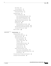
...switch console port is being accidentally removed. The LED colors have an RPS connector or a fan. To order a cable guard (CBLGRD-C3560-12PC or CBLGRD-C3560-8PC), contact your Cisco representative. Figure 1-13 Dual-Purpose Port LEDs 1 234 1 1 RJ-45 connector 3 SFP module port LED 2 RJ-45 port ... Rear Panel Description • Internal Power Supply, page 1-18 • Cisco RPS, page 1-19 • Console Port, page 1-19 • Security Slots, page 1-20 Note The Catalyst 3560-8PC and the Catalyst 3560-12PC-S switches do not have the same meaning as an SFP module, but not both...
...switch console port is being accidentally removed. The LED colors have an RPS connector or a fan. To order a cable guard (CBLGRD-C3560-12PC or CBLGRD-C3560-8PC), contact your Cisco representative. Figure 1-13 Dual-Purpose Port LEDs 1 234 1 1 RJ-45 connector 3 SFP module port LED 2 RJ-45 port ... Rear Panel Description • Internal Power Supply, page 1-18 • Cisco RPS, page 1-19 • Console Port, page 1-19 • Security Slots, page 1-20 Note The Catalyst 3560-8PC and the Catalyst 3560-12PC-S switches do not have the same meaning as an SFP module, but not both...
Hardware Installation Guide
Page 26
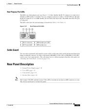
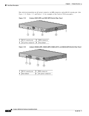
... panel has an AC power connector, an RPS connector, and an RJ-45 console port. (See Figure 1-14, Figure 1-15, and Figure 1-16 for examples of the Catalyst 3560 rear panels.) Figure 1-14 Catalyst 3560-24PS and 3560-48PS Switch Rear Panel CONSOLE 5.0A1-20R.05A-A2T,0IN500GV-6~0 HZ [email protected]@YMUO7A.TL8EA 97914 1 2 3 4 1 RJ...
... panel has an AC power connector, an RPS connector, and an RJ-45 console port. (See Figure 1-14, Figure 1-15, and Figure 1-16 for examples of the Catalyst 3560 rear panels.) Figure 1-14 Catalyst 3560-24PS and 3560-48PS Switch Rear Panel CONSOLE 5.0A1-20R.05A-A2T,0IN500GV-6~0 HZ [email protected]@YMUO7A.TL8EA 97914 1 2 3 4 1 RJ...

Hardware Installation Guide
Page 93
... 10/100/1000 Ports, page B-1 • SFP Module Ports, page B-2 • Dual-Purpose Ports, page B-3 • Console Port, page B-3 10/100 and 10/100/1000 Ports The 10/100 and 10/100/1000 Ethernet ports use standard RJ-45 connectors and Ethernet pinouts with internal crossovers. OL-6337-07 Catalyst 3560 Switch Hardware Installation Guide B-1 These ports have the send...
... 10/100/1000 Ports, page B-1 • SFP Module Ports, page B-2 • Dual-Purpose Ports, page B-3 • Console Port, page B-3 10/100 and 10/100/1000 Ports The 10/100 and 10/100/1000 Ethernet ports use standard RJ-45 connectors and Ethernet pinouts with internal crossovers. OL-6337-07 Catalyst 3560 Switch Hardware Installation Guide B-1 These ports have the send...


