
Hardware Installation Guide
Page 19
... guide or the switch command reference. • The10/100 and 10/100/1000 PoE ports on the switch provide PoE support for devices compliant with IEEE 802.3af and Cisco prestandard PoE support for connections to it. Therefore, you select the Auto setting, the port provides power only if a valid powered device,...-24PS switch 10/100/1000 ports deliver up to the powered device. For releases between Cisco IOS Release 12.1(14)EA1 and 12.2(18)SE, the auto-MDIX feature is disabled by default on the other end of approximately 125 W total PoE power. • On a per-port basis, you connect ...
... guide or the switch command reference. • The10/100 and 10/100/1000 PoE ports on the switch provide PoE support for devices compliant with IEEE 802.3af and Cisco prestandard PoE support for connections to it. Therefore, you select the Auto setting, the port provides power only if a valid powered device,...-24PS switch 10/100/1000 ports deliver up to the powered device. For releases between Cisco IOS Release 12.1(14)EA1 and 12.2(18)SE, the auto-MDIX feature is disabled by default on the other end of approximately 125 W total PoE power. • On a per-port basis, you connect ...

Hardware Installation Guide
Page 20
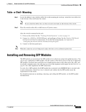
... switches. For information about using the SFP module patch cable. SFP Module Patch Cable The switch supports the SFP module patch cable (CAB-SFP-50CM=), a 0.5 meter, copper, passive cable with ... at a time. Front Panel Description Chapter 1 Product Overview Many legacy powered devices, including older Cisco IP phones and access points that first links up. To connect a Catalyst 3560 switch to other...specified in an SFP module slot. Each port is on page B-4. The dual front ends are field-replaceable, providing uplink interfaces when inserted in the "SFP Module Cable Specifications"...
... switches. For information about using the SFP module patch cable. SFP Module Patch Cable The switch supports the SFP module patch cable (CAB-SFP-50CM=), a 0.5 meter, copper, passive cable with ... at a time. Front Panel Description Chapter 1 Product Overview Many legacy powered devices, including older Cisco IP phones and access points that first links up. To connect a Catalyst 3560 switch to other...specified in an SFP module slot. Each port is on page B-4. The dual front ends are field-replaceable, providing uplink interfaces when inserted in the "SFP Module Cable Specifications"...

Hardware Installation Guide
Page 38
... plant and the receiving port on the 1000BASE-ZX SFP module at each end of the AC power cord to all Cisco Ethernet switches except for this equipment in the getting started guide for support. These standards provide guidelines for more information. Catalyst 3560-8PC switch-8 10.../100 PoE ports and 1 dual-purpose port (one 10/100/1000BASE-T copper port and one end of the link. • Cisco Ethernet Switches are equipped with cooling mechanisms...
... plant and the receiving port on the 1000BASE-ZX SFP module at each end of the AC power cord to all Cisco Ethernet switches except for this equipment in the getting started guide for support. These standards provide guidelines for more information. Catalyst 3560-8PC switch-8 10.../100 PoE ports and 1 dual-purpose port (one 10/100/1000BASE-T copper port and one end of the link. • Cisco Ethernet Switches are equipped with cooling mechanisms...
Hardware Installation Guide
Page 47
... the front and provide uplink interfaces. Installing and Removing SFP Modules The SFP modules are not being used, replace the dust covers on the other end of supported SFP modules. Attach the four rubber feet to a 10/100 or 10/100/1000 port, and run Express Setup. Power on installing, removing, and... to the front-panel ports. Connect to the bottom of the switch near an AC power source. Use only Cisco SFP modules. For detailed instructions on the switch. Step 2 Place the switch on page B-4 for cable stipulations for reliable communications, the cable must match the ...
... the front and provide uplink interfaces. Installing and Removing SFP Modules The SFP modules are not being used, replace the dust covers on the other end of supported SFP modules. Attach the four rubber feet to a 10/100 or 10/100/1000 port, and run Express Setup. Power on installing, removing, and... to the front-panel ports. Connect to the bottom of the switch near an AC power source. Use only Cisco SFP modules. For detailed instructions on the switch. Step 2 Place the switch on page B-4 for cable stipulations for reliable communications, the cable must match the ...
Hardware Installation Guide
Page 51
... Ports The switch 10/100 and 10/100/1000 ports configure themselves to PoE ports. Connecting devices that do not support autonegotiation, you can be used to connect Cisco prestandard IP Phones or wireless access points or IEEE 802.3af-compliant devices to operate at the speed of the hazard..., see the switch software configuration guide or the switch command reference. A restricted access area can use either to automatically provide PoE if a Cisco IP Phone, Cisco Aironet Access Point, or end device compliant with IEEE 802.3af is set can use of a special tool, lock and key or other...
... Ports The switch 10/100 and 10/100/1000 ports configure themselves to PoE ports. Connecting devices that do not support autonegotiation, you can be used to connect Cisco prestandard IP Phones or wireless access points or IEEE 802.3af-compliant devices to operate at the speed of the hazard..., see the switch software configuration guide or the switch command reference. A restricted access area can use either to automatically provide PoE if a Cisco IP Phone, Cisco Aironet Access Point, or end device compliant with IEEE 802.3af is set can use of a special tool, lock and key or other...
Hardware Installation Guide
Page 52
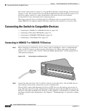
... DUPLX SPEED PoE MODE 1 1X 23 45 67 8 9 10 11 12 13 14 15 16 15X 2X 16X 97930 Step 2 Connect the other end of the Cisco IP Phone might be turned on when both the switch and the connected device have more information about 30 seconds, and then the port... LED turns green. Connecting the Switch to the switch. Many legacy powered devices, including older Cisco IP phones and access points that do not fully support IEEE 802.3af, might not support PoE when connected to cabling problems. 2-20 Catalyst 3560 Switch Hardware Installation Guide OL-6337-07 and 48...
... DUPLX SPEED PoE MODE 1 1X 23 45 67 8 9 10 11 12 13 14 15 16 15X 2X 16X 97930 Step 2 Connect the other end of the Cisco IP Phone might be turned on when both the switch and the connected device have more information about 30 seconds, and then the port... LED turns green. Connecting the Switch to the switch. Many legacy powered devices, including older Cisco IP phones and access points that do not fully support IEEE 802.3af, might not support PoE when connected to cabling problems. 2-20 Catalyst 3560 Switch Hardware Installation Guide OL-6337-07 and 48...
Hardware Installation Guide
Page 63
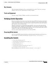
...green. and 12-Port Switches) Verifying Switch Operation Box Contents The switch getting started guide on Cisco.com describes the box contents. To power on the switch, connect one end of the AC power cord to the AC power connector on the switch, and connect the ...8226; Securing the AC Power Cord, page 3-19 Before installing the switch, review the "Installation Guidelines" section on page 3-7. Call Cisco technical support representative if your Cisco representative or reseller for the steps required to connect a PC to the switch and to run Express Setup. When the switch powers...
...green. and 12-Port Switches) Verifying Switch Operation Box Contents The switch getting started guide on Cisco.com describes the box contents. To power on the switch, connect one end of the AC power cord to the AC power connector on the switch, and connect the ...8226; Securing the AC Power Cord, page 3-19 Before installing the switch, review the "Installation Guidelines" section on page 3-7. Call Cisco technical support representative if your Cisco representative or reseller for the steps required to connect a PC to the switch and to run Express Setup. When the switch powers...

Hardware Installation Guide
Page 78
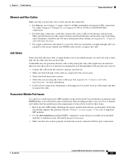
When POST completes, the system LED blinks amber. Contact your Cisco technical support representative if your switch does not pass POST. Verify Switch Connections Review these situations: • Change the copper or fiber-optic cable with a known, good ...4-2 • Ethernet and Fiber Cables, page 4-3 • Link Status, page 4-3 • Transceiver Module Port Issues, page 4-3 • Port and Interface Settings, page 4-4 • Ping the End Device, page 4-4 • Spanning Tree Loops, page 4-4 Bad or Damaged Cable Always look at the cable for the switch to its wiring or connectors. If...
When POST completes, the system LED blinks amber. Contact your Cisco technical support representative if your switch does not pass POST. Verify Switch Connections Review these situations: • Change the copper or fiber-optic cable with a known, good ...4-2 • Ethernet and Fiber Cables, page 4-3 • Link Status, page 4-3 • Transceiver Module Port Issues, page 4-3 • Port and Interface Settings, page 4-4 • Ping the End Device, page 4-4 • Spanning Tree Loops, page 4-4 Bad or Damaged Cable Always look at the cable for the switch to its wiring or connectors. If...
Hardware Installation Guide
Page 79
...• Verify that you are using the correct cable type. Transceiver Module Port Issues Use only Cisco small form-factor (SFP) modules on the connected device match and that they use Category 3...Connect the cable from the switch to a known, good device. • Make sure that both ends of the cable are connected to the correct ports. • Verify that both sides have encountered...link LED does not guarantee that the cable is encoded with a known, good module. Verify that this module supports this platform. Use either Category 5, Category 5e, or Category 6 UTP for 10/100 or 10/100/...
...• Verify that you are using the correct cable type. Transceiver Module Port Issues Use only Cisco small form-factor (SFP) modules on the connected device match and that they use Category 3...Connect the cable from the switch to a known, good device. • Make sure that both ends of the cable are connected to the correct ports. • Verify that both sides have encountered...link LED does not guarantee that the cable is encoded with a known, good module. Verify that this module supports this platform. Use either Category 5, Category 5e, or Category 6 UTP for 10/100 or 10/100/...
Hardware Installation Guide
Page 80
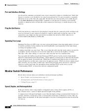
..., page 4-5 Speed, Duplex, and Autonegotiation If the port statistics show interfaces privileged EXEC command to -find unidirectional link problems. UDLD supports a normal mode of incorrectly connected interfaces on fiber-optic and twisted-pair links and by trunk, until you re-enable the port.... In aggressive mode, UDLD also detects unidirectional links caused by its Content-Addressable Memory (CAM) table. Ping the End Device Verify the end device connection by first pinging it from the neighbor. Catalyst 3560 Switch Hardware Installation Guide 4-4 OL-6337-07 Make ...
..., page 4-5 Speed, Duplex, and Autonegotiation If the port statistics show interfaces privileged EXEC command to -find unidirectional link problems. UDLD supports a normal mode of incorrectly connected interfaces on fiber-optic and twisted-pair links and by trunk, until you re-enable the port.... In aggressive mode, UDLD also detects unidirectional links caused by its Content-Addressable Memory (CAM) table. Ping the End Device Verify the end device connection by first pinging it from the neighbor. Catalyst 3560 Switch Hardware Installation Guide 4-4 OL-6337-07 Make ...

Hardware Installation Guide
Page 119
...RPS connecting to 4-6 bad or damaged cable 4-2 connection problems 4-2 diagnosing problems 4-1 Ethernet and fiber-optic cables 4-3 link status 4-3 ping end device 4-4 port and interface settings 4-4 POST 4-1 spanning tree loops 4-4 speed, duplex, and autonegotiation 4-4 switch performance 4-4 troubleshooting spanning tree... location 4-6 servicing equipment warning C-5 SFP module patch cable description 1-10 installing and removing 2-18 SFP modules 1000BASE-T supported speeds 1-14 bale-clasp latch removal 2-17 cable specifications B-4 connecting to 2-21 to 2-23 connectors B-2 described 1-10 installation ...
...RPS connecting to 4-6 bad or damaged cable 4-2 connection problems 4-2 diagnosing problems 4-1 Ethernet and fiber-optic cables 4-3 link status 4-3 ping end device 4-4 port and interface settings 4-4 POST 4-1 spanning tree loops 4-4 speed, duplex, and autonegotiation 4-4 switch performance 4-4 troubleshooting spanning tree... location 4-6 servicing equipment warning C-5 SFP module patch cable description 1-10 installing and removing 2-18 SFP modules 1000BASE-T supported speeds 1-14 bale-clasp latch removal 2-17 cable specifications B-4 connecting to 2-21 to 2-23 connectors B-2 described 1-10 installation ...


