
Hardware Installation Guide
Page 2
... users will not occur in accordance with the limits for a Class A digital device, pursuant to part 15 of Green are trademarks; All rights reserved. and Access Registrar, Aironet, AllTouch, AsyncOS, Bringing the Meeting To You, Catalyst, CCDA, CCDP, CCIE, CCIP, CCNA, CCNP, CCSP, CCVP, Cisco, the Cisco Certified Internetwork Expert logo, Cisco IOS, Cisco Lumin, Cisco Nexus, Cisco Press, Cisco Systems, Cisco Systems Capital, the Cisco...
... users will not occur in accordance with the limits for a Class A digital device, pursuant to part 15 of Green are trademarks; All rights reserved. and Access Registrar, Aironet, AllTouch, AsyncOS, Bringing the Meeting To You, Catalyst, CCDA, CCDP, CCIE, CCIP, CCNA, CCNP, CCSP, CCVP, Cisco, the Cisco Certified Internetwork Expert logo, Cisco IOS, Cisco Lumin, Cisco Nexus, Cisco Press, Cisco Systems, Cisco Systems Capital, the Cisco...

Hardware Installation Guide
Page 11
... can connect devices like workstations, Cisco Wireless Access Points, Cisco IP Phones, and other network devices such as backbone switches, aggregating 10BASE-T and 100BASE-TX Ethernet traffic from other switches. These topics are hot-swappable. The getting started guide provides switch management options, basic rack-mounting procedures, port and module connections, power connection procedures, and troubleshooting help. and 12-port switches include connections for instructions on setting up your Catalyst switch. OL-6337-07 Catalyst 3560 Switch Hardware Installation Guide 1-1 This...
... can connect devices like workstations, Cisco Wireless Access Points, Cisco IP Phones, and other network devices such as backbone switches, aggregating 10BASE-T and 100BASE-TX Ethernet traffic from other switches. These topics are hot-swappable. The getting started guide provides switch management options, basic rack-mounting procedures, port and module connections, power connection procedures, and troubleshooting help. and 12-port switches include connections for instructions on setting up your Catalyst switch. OL-6337-07 Catalyst 3560 Switch Hardware Installation Guide 1-1 This...

Hardware Installation Guide
Page 18
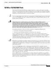
... and users and service people who are authorized within 328 feet (100 meters). Port 3 is above the second member (port 2) on . In all cases, the attached device must be accessed only through the use Category 3 or Category 4 cables. Statement 1072 • 100BASE-TX and 1000BASE-T traffic requires Category 5 cable. 10BASE-T traffic can configure duplex mode to half, full, or autonegotiate on Gigabit Ethernet interfaces if the speed...
... and users and service people who are authorized within 328 feet (100 meters). Port 3 is above the second member (port 2) on . In all cases, the attached device must be accessed only through the use Category 3 or Category 4 cables. Statement 1072 • 100BASE-TX and 1000BASE-T traffic requires Category 5 cable. 10BASE-T traffic can configure duplex mode to half, full, or autonegotiate on Gigabit Ethernet interfaces if the speed...

Hardware Installation Guide
Page 19
... connected. The Auto setting is enabled, the switch detects the required cable type for the powered device. In that case, the PoE port becomes the backup power source for copper Ethernet connections and configures the interfaces accordingly. When the feature is the default. - Never: When you can connect a Cisco IP Phone or Cisco Aironet Access Point to a Catalyst 3560 PoE switch 10/100 or 10/100/1000 port and to the powered device. The device manager, Network Assistant, and the CLI provide PoE settings for redundant power...
... connected. The Auto setting is enabled, the switch detects the required cable type for the powered device. In that case, the PoE port becomes the backup power source for copper Ethernet connections and configures the interfaces accordingly. When the feature is the default. - Never: When you can connect a Cisco IP Phone or Cisco Aironet Access Point to a Catalyst 3560 PoE switch 10/100 or 10/100/1000 port and to the powered device. The device manager, Network Assistant, and the CLI provide PoE settings for redundant power...

Hardware Installation Guide
Page 20
...-07 SFP Modules The switch uses Gigabit Ethernet SFP modules to the switches by a crossover cable. Each uplink port has two LEDs. Each port is on for the latest list of the pair at each end (see Figure 1-11). Front Panel Description Chapter 1 Product Overview Many legacy powered devices, including older Cisco IP phones and access points that first links up. These transceiver modules are not redundant interfaces. However, you must use the media-type interface configuration command to...
...-07 SFP Modules The switch uses Gigabit Ethernet SFP modules to the switches by a crossover cable. Each uplink port has two LEDs. Each port is on for the latest list of the pair at each end (see Figure 1-11). Front Panel Description Chapter 1 Product Overview Many legacy powered devices, including older Cisco IP phones and access points that first links up. These transceiver modules are not redundant interfaces. However, you must use the media-type interface configuration command to...
Hardware Installation Guide
Page 31
...to the switch console port or by using Telnet from a remote management station. Network Configurations See the switch software configuration guide on Cisco.com for more information. See the CiscoView documentation for more information. For setup instructions that use the switch to support desktop-switching features. See the Catalyst 3560 Switch Command Reference on Cisco.com for more information. • SNMP network management You can manage switches from the CLI. See the switch software configuration guide on Cisco IOS software and is enhanced to create dedicated network...
...to the switch console port or by using Telnet from a remote management station. Network Configurations See the switch software configuration guide on Cisco.com for more information. See the CiscoView documentation for more information. For setup instructions that use the switch to support desktop-switching features. See the Catalyst 3560 Switch Command Reference on Cisco.com for more information. • SNMP network management You can manage switches from the CLI. See the switch software configuration guide on Cisco IOS software and is enhanced to create dedicated network...
Hardware Installation Guide
Page 34
...chassis; Statement 378 Catalyst 3560 Switch Hardware Installation Guide 2-2 OL-6337-07 Statement 17B Warning Before working on any other equipment; Preparing for the Catalyst 3560 Switch. Metal objects will heat up when connected to the switch, install...openings. Statement 171 Warning If a redundant power system (RPS) is connected to the RPS receptacle: PWR-RPS2300 / PWR675-AC-RPS-N1 Statement 370 Warning Read the wall-mounting instructions carefully before beginning installation. Statement 265 Warning Attach only the following Cisco RPS model to power lines, remove...
...chassis; Statement 378 Catalyst 3560 Switch Hardware Installation Guide 2-2 OL-6337-07 Statement 17B Warning Before working on any other equipment; Preparing for the Catalyst 3560 Switch. Metal objects will heat up when connected to the switch, install...openings. Statement 171 Warning If a redundant power system (RPS) is connected to the RPS receptacle: PWR-RPS2300 / PWR675-AC-RPS-N1 Statement 370 Warning Read the wall-mounting instructions carefully before beginning installation. Statement 265 Warning Attach only the following Cisco RPS model to power lines, remove...

Hardware Installation Guide
Page 36
... No user-serviceable parts inside. Statement 1074 Catalyst 3560 Switch Hardware Installation Guide 2-4 OL-6337-07 Statement 1024 Warning This unit might have more than one power supply connection. Use the statement number provided at the end of security. Statement 1071 Warning Voltages that suitable grounding is installed, the following ports must comply with standard practices for Installation Chapter 2 Switch Installation (24- Statement 1073 Warning Installation of the hazard. A restricted access...
... No user-serviceable parts inside. Statement 1074 Catalyst 3560 Switch Hardware Installation Guide 2-4 OL-6337-07 Statement 1024 Warning This unit might have more than one power supply connection. Use the statement number provided at the end of security. Statement 1071 Warning Voltages that suitable grounding is installed, the following ports must comply with standard practices for Installation Chapter 2 Switch Installation (24- Statement 1073 Warning Installation of the hazard. A restricted access...

Hardware Installation Guide
Page 38
... the getting started guide for support. and 48-Port Switches) When the fiber-optic cable span is missing or damaged, contact your configuration has an RPS, connect the switch and the RPS to run Express Setup. These standards provide guidelines for more information. Statement 370 Catalyst 3560 Switch Hardware Installation Guide 2-6 OL-6337-07 To power on the switch, connect one SFP module slot) Box Contents The switch getting started guide on the 1000BASE-ZX SFP module at...
... the getting started guide for support. and 48-Port Switches) When the fiber-optic cable span is missing or damaged, contact your configuration has an RPS, connect the switch and the RPS to run Express Setup. These standards provide guidelines for more information. Statement 370 Catalyst 3560 Switch Hardware Installation Guide 2-6 OL-6337-07 To power on the switch, connect one SFP module slot) Box Contents The switch getting started guide on the 1000BASE-ZX SFP module at...
Hardware Installation Guide
Page 51
... to PoE ports. Connecting devices that do not support autonegotiation, you can use the mdix auto interface configuration command in no linkage. You cannot configure half-duplex mode on Gigabit Ethernet interfaces if the interface speed is Auto. The default setting is 1000 Mb/s. Only standard-compliant cabling can reduce performance or result in the CLI to a copper 10/100, 10/100/1000, or 1000BASE-T SFP module port on the switch, regardless of the type of device on Gigabit Ethernet interfaces...
... to PoE ports. Connecting devices that do not support autonegotiation, you can use the mdix auto interface configuration command in no linkage. You cannot configure half-duplex mode on Gigabit Ethernet interfaces if the interface speed is Auto. The default setting is 1000 Mb/s. Only standard-compliant cabling can reduce performance or result in the CLI to a copper 10/100, 10/100/1000, or 1000BASE-T SFP module port on the switch, regardless of the type of device on Gigabit Ethernet interfaces...

Hardware Installation Guide
Page 58
... 370 Warning Read the wall-mounting instructions carefully before beginning installation. and they prevent exposure to the terminals. Preparing for the Catalyst 3560 Switch. Metal objects will heat up when connected to power and ground and can cause serious burns or weld the metal object to hazardous voltages and currents inside the chassis; Statement 122 Warning Blank faceplates...
... 370 Warning Read the wall-mounting instructions carefully before beginning installation. and they prevent exposure to the terminals. Preparing for the Catalyst 3560 Switch. Metal objects will heat up when connected to power and ground and can cause serious burns or weld the metal object to hazardous voltages and currents inside the chassis; Statement 122 Warning Blank faceplates...
Hardware Installation Guide
Page 72
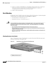
... the front-panel ports. Connect to the opposite side. To use the CLI setup program, see Appendix D, "Configuring the Switch with stabilizing devices, install the stabilizers before mounting or servicing the unit in a rack, you must take special precautions to ensure that is not included with the switch (RCKMNT-19-CMPCT=). • Attaching Brackets to the Switch, page 3-16 • Mounting the Switch in a 19-Inch Rack, page...
... the front-panel ports. Connect to the opposite side. To use the CLI setup program, see Appendix D, "Configuring the Switch with stabilizing devices, install the stabilizers before mounting or servicing the unit in a rack, you must take special precautions to ensure that is not included with the switch (RCKMNT-19-CMPCT=). • Attaching Brackets to the Switch, page 3-16 • Mounting the Switch in a 19-Inch Rack, page...
Hardware Installation Guide
Page 77
... "LEDs" section on the front panel provide troubleshooting information about the switch. See the software configuration guide, the switch command reference guide on self-test (POST), port-connectivity problems, and overall switch performance. They show POST failures, port-connectivity problems, and overall switch performance. This chapter describes these topics for details. You can also get statistics from the CLI or from a Simple Network Management Protocol (SNMP) workstation. They show failures in the power-on Cisco.com, or the documentation...
... "LEDs" section on the front panel provide troubleshooting information about the switch. See the software configuration guide, the switch command reference guide on self-test (POST), port-connectivity problems, and overall switch performance. They show POST failures, port-connectivity problems, and overall switch performance. This chapter describes these topics for details. You can also get statistics from the CLI or from a Simple Network Management Protocol (SNMP) workstation. They show failures in the power-on Cisco.com, or the documentation...
Hardware Installation Guide
Page 79
.... Exchange the suspect module with security information. Each Cisco module has an internal serial EEPROM that is encoded with a known, good module. Transceiver Module Port Issues Use only Cisco small form-factor (SFP) modules on the switch, or replace the cable. A link LED does not guarantee that the cable is not. Re-enable the port if necessary. • Make sure that all fiber-optic connections. Chapter 4 Troubleshooting Diagnosing Problems Ethernet and Fiber Cables Make sure that you...
.... Exchange the suspect module with security information. Each Cisco module has an internal serial EEPROM that is encoded with a known, good module. Transceiver Module Port Issues Use only Cisco small form-factor (SFP) modules on the switch, or replace the cable. A link LED does not guarantee that the cable is not. Re-enable the port if necessary. • Make sure that all fiber-optic connections. Chapter 4 Troubleshooting Diagnosing Problems Ethernet and Fiber Cables Make sure that you...
Hardware Installation Guide
Page 80
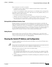
... duplex settings are mismatched between two switches, between a switch and a router, or between the two devices. This can enable the UniDirectional Link Detection (UDLD) protocol on fiber-optic links. You can happen when you troubleshoot switch performance problems: • Speed, Duplex, and Autonegotiation, page 4-4 • Autonegotiation and Network Interface Cards, page 4-5 • Cabling Distance, page 4-5 Speed, Duplex, and Autonegotiation If the port statistics show interfaces privileged EXEC command to verify the port or interface error-disabled, disabled...
... duplex settings are mismatched between two switches, between a switch and a router, or between the two devices. This can enable the UniDirectional Link Detection (UDLD) protocol on fiber-optic links. You can happen when you troubleshoot switch performance problems: • Speed, Duplex, and Autonegotiation, page 4-4 • Autonegotiation and Network Interface Cards, page 4-5 • Cabling Distance, page 4-5 Speed, Duplex, and Autonegotiation If the port statistics show interfaces privileged EXEC command to verify the port or interface error-disabled, disabled...
Hardware Installation Guide
Page 81
... causing the problem. Cabling Distance If the port statistics show excessive FCS, late-collision, or alignment errors, verify that is set to the latest version available from the manufacturer. If the switch is common for cabling guidelines. The speed parameter can adjust itself even if the connected port does not autonegotiate. It is not configured, the LEDs above the Mode button turn green. Upgrade the NIC card driver to autonegotiate...
... causing the problem. Cabling Distance If the port statistics show excessive FCS, late-collision, or alignment errors, verify that is set to the latest version available from the manufacturer. If the switch is common for cabling guidelines. The speed parameter can adjust itself even if the connected port does not autonegotiate. It is not configured, the LEDs above the Mode button turn green. Upgrade the NIC card driver to autonegotiate...

Hardware Installation Guide
Page 111
... a Cisco redundant power system (RPS), see the documentation that the switch functions properly. On a command switch, the host name is in a host name for management of tests that verifies that shipped with your RPS. on a member switch to 28 characters; Enter enable secret: secret_password OL-6337-07 Catalyst 3560 Switch Hardware Installation Guide D-3 Use ctrl-c to configure each interface on the system. Basic management setup configures only enough connectivity for any switch. Would...
... a Cisco redundant power system (RPS), see the documentation that the switch functions properly. On a command switch, the host name is in a host name for management of tests that verifies that shipped with your RPS. on a member switch to 28 characters; Enter enable secret: secret_password OL-6337-07 Catalyst 3560 Switch Hardware Installation Guide D-3 Use ctrl-c to configure each interface on the system. Basic management setup configures only enough connectivity for any switch. Would...
Hardware Installation Guide
Page 113
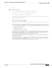
... 2, "Switch Installation (24- After you complete the setup program, the switch can run the default configuration that you want to change this configuration to perform other management tasks, use one of these tools: • Command-line interface (CLI) • CMS from your browser • Network Assistant from your browser To use CMS, see the switch software configuration guide or the switch command reference. To use the CLI, enter commands at the Switch> prompt through the console port by using a terminal...
... 2, "Switch Installation (24- After you complete the setup program, the switch can run the default configuration that you want to change this configuration to perform other management tasks, use one of these tools: • Command-line interface (CLI) • CMS from your browser • Network Assistant from your browser To use CMS, see the switch software configuration guide or the switch command reference. To use the CLI, enter commands at the Switch> prompt through the console port by using a terminal...

Hardware Installation Guide
Page 116
...-mounting 24- Index torquing recommendation C-6 Cisco IOS command-line interface 1-21 Cisco IP Phones, connecting to 1-9, 2-20 Cisco Network Assistant 1-20 Cisco RPS See RPS CiscoView 1-21 CLI to manage switch 1-21 to set up switch D-1 code compliance warning 2-4, 3-4 command-line interface See CLI configuration examples, network 1-1 connecting to 10/100/1000 ports 2-19 to 10/100 ports 2-19 to console port B-3 to DC power C-1 to C-2 to SFP modules 2-21 to 2-23 connection procedures 2-19 to 2-23 connectors and cables 10/100 ports B-2 console port B-3 to B-8 dual-purpose ports B-3 power...
...-mounting 24- Index torquing recommendation C-6 Cisco IOS command-line interface 1-21 Cisco IP Phones, connecting to 1-9, 2-20 Cisco Network Assistant 1-20 Cisco RPS See RPS CiscoView 1-21 CLI to manage switch 1-21 to set up switch D-1 code compliance warning 2-4, 3-4 command-line interface See CLI configuration examples, network 1-1 connecting to 10/100/1000 ports 2-19 to 10/100 ports 2-19 to console port B-3 to DC power C-1 to C-2 to SFP modules 2-21 to 2-23 connection procedures 2-19 to 2-23 connectors and cables 10/100 ports B-2 console port B-3 to B-8 dual-purpose ports B-3 power...

Hardware Installation Guide
Page 119
...-T supported speeds 1-14 bale-clasp latch removal 2-17 cable specifications B-4 connecting to 2-21 to 2-23 connectors B-2 described 1-10 installation 2-16 to 4-6 bad or damaged cable 4-2 connection problems 4-2 diagnosing problems 4-1 Ethernet and fiber-optic cables 4-3 link status 4-3 ping end device 4-4 port and interface settings 4-4 POST 4-1 spanning tree loops 4-4 speed, duplex, and autonegotiation 4-4 switch performance 4-4 troubleshooting spanning tree loops 4-4 W wall-mounting 24- and 48-port switches 2-7, 2-11 8- and 12-port switches 3-8 Simple Network Management Protocol...
...-T supported speeds 1-14 bale-clasp latch removal 2-17 cable specifications B-4 connecting to 2-21 to 2-23 connectors B-2 described 1-10 installation 2-16 to 4-6 bad or damaged cable 4-2 connection problems 4-2 diagnosing problems 4-1 Ethernet and fiber-optic cables 4-3 link status 4-3 ping end device 4-4 port and interface settings 4-4 POST 4-1 spanning tree loops 4-4 speed, duplex, and autonegotiation 4-4 switch performance 4-4 troubleshooting spanning tree loops 4-4 W wall-mounting 24- and 48-port switches 2-7, 2-11 8- and 12-port switches 3-8 Simple Network Management Protocol...


