Hardware Installation Guide
Page 62
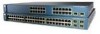
...-63-CORE - National Electrical Manufacturers Association (NEMA) Type 1 - To order a cable guard (CBLGRD-C3560-12PC or CBLGRD-C3560-8PC), contact your Cisco representative. Catalyst 3560-8PC switch-8 10/100 PoE ports and 1 dual-purpose port (one 10/100/1000BASE-T copper port and one SFP...Switches are available from other particles, causing contaminant buildup inside the chassis, which lists the cable specifications for 1000BASE-X and 100BASE-X SFP modules for this equipment in the left and right side panels. Make sure the cabling is safely away from most computer accessory...
...-63-CORE - National Electrical Manufacturers Association (NEMA) Type 1 - To order a cable guard (CBLGRD-C3560-12PC or CBLGRD-C3560-8PC), contact your Cisco representative. Catalyst 3560-8PC switch-8 10/100 PoE ports and 1 dual-purpose port (one 10/100/1000BASE-T copper port and one SFP...Switches are available from other particles, causing contaminant buildup inside the chassis, which lists the cable specifications for 1000BASE-X and 100BASE-X SFP modules for this equipment in the left and right side panels. Make sure the cabling is safely away from most computer accessory...

Hardware Installation Guide
Page 64
...top of the desk or shelf, as shown in the accessory kit. Place the switch on the bottom of the desk or shelf after the switch is also a guide for making sure that the screws... (Unsecured) Step 1 Step 2 Locate the adhesive strip with the rubber feet in Figure 3-1. They prevent the switch from the adhesive strip, and attach them to the desk or shelf. Desk or Shelf Mounting (Secured) Step... Peel the adhesive strip off the bottom of the desk or shelf. Catalyst 3560 Switch Hardware Installation Guide 3-8 OL-6337-07 Doing so improves airflow and reduces overheating. Installing the...
...top of the desk or shelf, as shown in the accessory kit. Place the switch on the bottom of the desk or shelf after the switch is also a guide for making sure that the screws... (Unsecured) Step 1 Step 2 Locate the adhesive strip with the rubber feet in Figure 3-1. They prevent the switch from the adhesive strip, and attach them to the desk or shelf. Desk or Shelf Mounting (Secured) Step... Peel the adhesive strip off the bottom of the desk or shelf. Catalyst 3560 Switch Hardware Installation Guide 3-8 OL-6337-07 Doing so improves airflow and reduces overheating. Installing the...
Hardware Installation Guide
Page 102
...Catalyst 3560 Switch Hardware Installation Guide C-2 OL-6337-07 Never defeat the ground conductor or operate the equipment in Figure C-1. Set the screws and the ground lug aside. To ground the switch... on the switch rear panel and the DC terminal block plug in... and 18-gauge wires Grounding the Switch Warning This equipment must be grounded....10-32 ground-lug screws from the rear panel of the switch. (See Figure C-3 for location.) Use a standard Phillips screwdriver...C Connecting to DC Power Caution The Catalyst 3560V2-24TS-SD switch is available. Contact the appropriate electrical ...
...Catalyst 3560 Switch Hardware Installation Guide C-2 OL-6337-07 Never defeat the ground conductor or operate the equipment in Figure C-1. Set the screws and the ground lug aside. To ground the switch... on the switch rear panel and the DC terminal block plug in... and 18-gauge wires Grounding the Switch Warning This equipment must be grounded....10-32 ground-lug screws from the rear panel of the switch. (See Figure C-3 for location.) Use a standard Phillips screwdriver...C Connecting to DC Power Caution The Catalyst 3560V2-24TS-SD switch is available. Contact the appropriate electrical ...