Hardware Installation Guide
Page 34
...back of 113•F (45•C). Statement 378 Warning Do not work on any other equipment. Statement 43 Warning Do not stack the chassis on the system or connect or disconnect cables during periods of clearance around the ventilation openings. and 48-Port Switches...) Warnings These warnings are translated into several languages in a central office environment. Statement 265 Warning Attach only the following Cisco RPS model to the system. Statement 370 Warning Read the wall-mounting instructions carefully before connecting the system to power lines, remove ...
...back of 113•F (45•C). Statement 378 Warning Do not work on any other equipment. Statement 43 Warning Do not stack the chassis on the system or connect or disconnect cables during periods of clearance around the ventilation openings. and 48-Port Switches...) Warnings These warnings are translated into several languages in a central office environment. Statement 265 Warning Attach only the following Cisco RPS model to the system. Statement 370 Warning Read the wall-mounting instructions carefully before connecting the system to power lines, remove ...

Hardware Installation Guide
Page 56
... (PoE) IEEE 802.3af compliant power source or an IEC60950 compliant limited power source. Statement 1006 Warning Class 1 laser product. Statement 43 Warning Do not stack the chassis on the system or connect or disconnect cables during periods of lightning activity. Statement 1019 Catalyst 2960 Switch Hardware Installation Guide 3-2 OL-7075...
... (PoE) IEEE 802.3af compliant power source or an IEC60950 compliant limited power source. Statement 1006 Warning Class 1 laser product. Statement 43 Warning Do not stack the chassis on the system or connect or disconnect cables during periods of lightning activity. Statement 1019 Catalyst 2960 Switch Hardware Installation Guide 3-2 OL-7075...

Hardware Installation Guide
Page 58
...panels. Preparing for Installation Chapter 3 Switch Installation (8-Port Switches) • Do not stack switches or place switches side-by-side unless they are available from most computer accessory...You can easily read the front-panel indicators. - To order a cable guard, contact your Cisco representative and use shorter lengths of the link. When you use these conditions - For information ... Catalyst 2960-8TC-L, 2960-8TC-S, and 2960PD-8TT-L switches cable guard part number: CBLGRD-C2960-8TC= • Catalyst 2960G-8TC-L switch cable guard part number: CBLGRD-C2960G-8TC= The...
...panels. Preparing for Installation Chapter 3 Switch Installation (8-Port Switches) • Do not stack switches or place switches side-by-side unless they are available from most computer accessory...You can easily read the front-panel indicators. - To order a cable guard, contact your Cisco representative and use shorter lengths of the link. When you use these conditions - For information ... Catalyst 2960-8TC-L, 2960-8TC-S, and 2960PD-8TT-L switches cable guard part number: CBLGRD-C2960-8TC= • Catalyst 2960G-8TC-L switch cable guard part number: CBLGRD-C2960G-8TC= The...

Hardware Installation Guide
Page 60
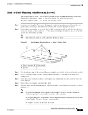
... run Express Setup. and 48-Port Switches)." Remove the four rubber feet from each other Catalyst 2960 switches, see Chapter 2, "Switch Installation (24- Do not stack switches or place switches side-by at least 3 inches (7.6 cm) of the switch. Do not place any items on the desk or shelf. Connect to...
... run Express Setup. and 48-Port Switches)." Remove the four rubber feet from each other Catalyst 2960 switches, see Chapter 2, "Switch Installation (24- Do not stack switches or place switches side-by at least 3 inches (7.6 cm) of the switch. Do not place any items on the desk or shelf. Connect to...
Hardware Installation Guide
Page 61
... drill a 1/2-inch (12.7 mm) hole in Figure 3-2. Note We strongly recommend that you attach the screw template to the top of the switch. Do not stack switches or place switches side-by -side slots face the front of the desk or shelf, as shown in the three screw template slots. Remove...
... drill a 1/2-inch (12.7 mm) hole in Figure 3-2. Note We strongly recommend that you attach the screw template to the top of the switch. Do not stack switches or place switches side-by -side slots face the front of the desk or shelf, as shown in the three screw template slots. Remove...

Hardware Installation Guide
Page 107
...See SNMP SNMP network management platforms 1-22 software switch management 1-22 specifications A-1 speed, troubleshooting 4-4 stacking the chassis warning 2-2, 3-2 straight-through cable pinout four twisted-pair 1000BASE-T ports B-6 two twisted...spanning tree loops 4-4 speed, duplex, and autonegotiation 4-4 switch performance 4-4 troubleshooting spanning tree loops 4-4 W wall-mounting 2-11, 3-16 warnings attaching the Cisco RPS 2-2, 2-6 circuit protection 2-3 class 1 laser product 2-3, 3-2 disconnecting device 2-3 Ethernet cables 2-2, 3-2 Ethernet ports 3-3 ground connection 2-4, 3-3 grounded ...
...See SNMP SNMP network management platforms 1-22 software switch management 1-22 specifications A-1 speed, troubleshooting 4-4 stacking the chassis warning 2-2, 3-2 straight-through cable pinout four twisted-pair 1000BASE-T ports B-6 two twisted...spanning tree loops 4-4 speed, duplex, and autonegotiation 4-4 switch performance 4-4 troubleshooting spanning tree loops 4-4 W wall-mounting 2-11, 3-16 warnings attaching the Cisco RPS 2-2, 2-6 circuit protection 2-3 class 1 laser product 2-3, 3-2 disconnecting device 2-3 Ethernet cables 2-2, 3-2 Ethernet ports 3-3 ground connection 2-4, 3-3 grounded ...

Hardware Installation Guide
Page 108
Index read the wall-mounting instructions 2-2, 3-11, 3-17 restricted access area 2-3 RPS 2-2, 2-13 stacking the chassis 2-2, 3-2 trained and qualified personnel 2-3 IN-6 Catalyst 2960 Switch Hardware Installation Guide OL-7075-09
Index read the wall-mounting instructions 2-2, 3-11, 3-17 restricted access area 2-3 RPS 2-2, 2-13 stacking the chassis 2-2, 3-2 trained and qualified personnel 2-3 IN-6 Catalyst 2960 Switch Hardware Installation Guide OL-7075-09