
Hardware Installation Guide
Page 2
... Guide © 2005-2010 Cisco Systems, Inc. The following information is no longer complying with the limits for Class A or Class B digital devices. However, there is for a Class B digital device in accordance with the specifications in part 15 of its affiliates... following information is not installed in a residential installation. These specifications are designed to operate the product. In that event, your authority to provide reasonable protection against such interference in accordance with Cisco's installation instructions, it was probably caused by FCC regulations,...
... Guide © 2005-2010 Cisco Systems, Inc. The following information is no longer complying with the limits for Class A or Class B digital devices. However, there is for a Class B digital device in accordance with the specifications in part 15 of its affiliates... following information is not installed in a residential installation. These specifications are designed to operate the product. In that event, your authority to provide reasonable protection against such interference in accordance with Cisco's installation instructions, it was probably caused by FCC regulations,...

Hardware Installation Guide
Page 5
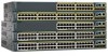
... Switch Performance 4-4 Speed, Duplex, and Autonegotiation 4-4 Autonegotiation and NIC Cards 4-5 Cabling Distance 4-5 Clearing the Switch IP Address and Configuration 4-5 Locating the Switch Serial Number 4-6 Technical Specifications A-1 Connector and Cable Specifications B-1 Connector Specifications B-1 10/100/1000 Ports B-1 Connecting to 1000BASE-T Devices B-2 SFP Module Ports B-3 Dual-Purpose Ports B-3 Catalyst 2960 Switch Hardware Installation Guide v
... Switch Performance 4-4 Speed, Duplex, and Autonegotiation 4-4 Autonegotiation and NIC Cards 4-5 Cabling Distance 4-5 Clearing the Switch IP Address and Configuration 4-5 Locating the Switch Serial Number 4-6 Technical Specifications A-1 Connector and Cable Specifications B-1 Connector Specifications B-1 10/100/1000 Ports B-1 Connecting to 1000BASE-T Devices B-2 SFP Module Ports B-3 Dual-Purpose Ports B-3 Catalyst 2960 Switch Hardware Installation Guide v

Hardware Installation Guide
Page 6
Contents C A P P E N D I X INDEX Console Port B-4 Cable and Adapter Specifications B-4 SFP Module Cable Specifications B-4 Two Twisted-Pair Cable Pinouts B-6 Four Twisted-Pair Cable Pinouts for 1000BASE-T Ports B-6 Crossover Cable and Adapter Pinouts B-7 Identifying a Crossover Cable B-7 Adapter Pinouts B-8 Configuring the ...
Contents C A P P E N D I X INDEX Console Port B-4 Cable and Adapter Specifications B-4 SFP Module Cable Specifications B-4 Two Twisted-Pair Cable Pinouts B-6 Four Twisted-Pair Cable Pinouts for 1000BASE-T Ports B-6 Crossover Cable and Adapter Pinouts B-7 Identifying a Crossover Cable B-7 Adapter Pinouts B-8 Configuring the ...

Hardware Installation Guide
Page 13
... to the switch. For specific information about switch support for an optional Cisco RPS 2300 or Cisco RPS 675 redundant power system that operates on specific switches, see the Cisco Gigabit Ethernet Transceiver Modules Compatibility Matrix at this Cisco.com URL: http://www.cisco.com/en/US/docs/interfaces_modules...100 Mb/s in half-duplex mode when installed in Catalyst 2960 switches. See the compatibility matrix documents for the RPS systems on Cisco.com for more information about which SFP modules are the SFP modules supported by the switches: • 1000BASE-CWDM • 1000BASE...
... to the switch. For specific information about switch support for an optional Cisco RPS 2300 or Cisco RPS 675 redundant power system that operates on specific switches, see the Cisco Gigabit Ethernet Transceiver Modules Compatibility Matrix at this Cisco.com URL: http://www.cisco.com/en/US/docs/interfaces_modules...100 Mb/s in half-duplex mode when installed in Catalyst 2960 switches. See the compatibility matrix documents for the RPS systems on Cisco.com for more information about which SFP modules are the SFP modules supported by the switches: • 1000BASE-CWDM • 1000BASE...

Hardware Installation Guide
Page 21
...that the cable is enabled, the switch detects the required cable type for the cables are described in Appendix B, "Connector and Cable Specifications." When the auto-MDIX feature is a straight-through cable. Therefore, you can use either a crossover or a straight-through or crossover... or a straight-through cable. You can set these ports for proper operation. When you connect the switch to workstations, servers, routers, and Cisco IP Phones, be within 328 feet (100 meters). 100BASE-TX traffic requires a Category 5 or higher cable. 10BASE-T traffic can use a twisted...
...that the cable is enabled, the switch detects the required cable type for the cables are described in Appendix B, "Connector and Cable Specifications." When the auto-MDIX feature is a straight-through cable. Therefore, you can use either a crossover or a straight-through or crossover... or a straight-through cable. You can set these ports for proper operation. When you connect the switch to workstations, servers, routers, and Cisco IP Phones, be within 328 feet (100 meters). 100BASE-TX traffic requires a Category 5 or higher cable. 10BASE-T traffic can use a twisted...

Hardware Installation Guide
Page 23
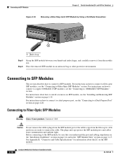
... module documentation or the release notes for a dual-purpose uplink, see Appendix B, "Connector and Cable Specifications." Each port is considered as an SFP module port. For information about configuring speed and duplex settings for your Cisco representative. (See Figure 1-22.) OL-7075-09 Catalyst 2960 Switch Hardware Installation Guide 1-13 Each uplink...
... module documentation or the release notes for a dual-purpose uplink, see Appendix B, "Connector and Cable Specifications." Each port is considered as an SFP module port. For information about configuring speed and duplex settings for your Cisco representative. (See Figure 1-22.) OL-7075-09 Catalyst 2960 Switch Hardware Installation Guide 1-13 Each uplink...

Hardware Installation Guide
Page 31
...can order a kit (part number ACS-DSBUASYN=) containing that adapter from Cisco. You can connect the switch to one failed switch at a time. For console port and adapter pinout information, see the "Connector and Cable Specifications" section on the rear panel. It automatically senses when the internal power...by the RPS • Obtain status reports for the RPS power-supply module • Read and monitor backup, failure, and exception history Cisco RPS 675 The Cisco 675 RPS is a redundant power system that supports six network devices and provides power to a PC by means of the switch. The...
...can order a kit (part number ACS-DSBUASYN=) containing that adapter from Cisco. You can connect the switch to one failed switch at a time. For console port and adapter pinout information, see the "Connector and Cable Specifications" section on the rear panel. It automatically senses when the internal power...by the RPS • Obtain status reports for the RPS power-supply module • Read and monitor backup, failure, and exception history Cisco RPS 675 The Cisco 675 RPS is a redundant power system that supports six network devices and provides power to a PC by means of the switch. The...

Hardware Installation Guide
Page 36
...must install this equipment in a system malfunction. Statement 1072 Warning No user-serviceable parts inside the chassis, which lists the cable specifications for 1000BASE-X and 100BASE-X SFP modules for the Catalyst 2960 switch. For information applicable to the Catalyst 2960 8-port switches....switch, be accessed only through the use both GLC-GE-100XX and GLC-FE-100XX SFP modules. Preparing for Particulate Matter Cisco Ethernet switches are equipped with local and national electrical codes. Avoid using uninsulated exposed metal contacts, conductors, or terminals. ...
...must install this equipment in a system malfunction. Statement 1072 Warning No user-serviceable parts inside the chassis, which lists the cable specifications for 1000BASE-X and 100BASE-X SFP modules for the Catalyst 2960 switch. For information applicable to the Catalyst 2960 8-port switches....switch, be accessed only through the use both GLC-GE-100XX and GLC-FE-100XX SFP modules. Preparing for Particulate Matter Cisco Ethernet switches are equipped with local and national electrical codes. Avoid using uninsulated exposed metal contacts, conductors, or terminals. ...

Hardware Installation Guide
Page 37
...connect the other devices that the switch passes POST. Tools and Equipment You need to insert an inline optical attenuator in Appendix A, "Technical Specifications." • Clearance to the switch, put the RPS in a closed or multirack assembly, the temperature around it might damage the cables.... the receiver. If the switch is less than normal room temperature. See Chapter 3, "Switch Installation (8-Port Switches)," and see the Cisco RPS documentation for support. and 48-Port Switches) Verifying Switch Operation When you use shorter lengths of the link. • The ...
...connect the other devices that the switch passes POST. Tools and Equipment You need to insert an inline optical attenuator in Appendix A, "Technical Specifications." • Clearance to the switch, put the RPS in a closed or multirack assembly, the temperature around it might damage the cables.... the receiver. If the switch is less than normal room temperature. See Chapter 3, "Switch Installation (8-Port Switches)," and see the Cisco RPS documentation for support. and 48-Port Switches) Verifying Switch Operation When you use shorter lengths of the link. • The ...

Hardware Installation Guide
Page 38
Statement 370 As the switch powers on page 2-6. Call Cisco technical support representative if your specific switch; This section describes these installation procedures: • Rack-Mounting, page 2-6 • Wall-Mounting, page 2-11 • Table- however, the instructions .... After a successful POST, disconnect the power cord from the bottom to the RPS receptacle: PWR-RPS2300, PWR675-AC-RPS-N1=. The following Cisco RPS model to the top with stabilizing devices, install the stabilizers before mounting or servicing the unit in a rack, you must take special precautions...
Statement 370 As the switch powers on page 2-6. Call Cisco technical support representative if your specific switch; This section describes these installation procedures: • Rack-Mounting, page 2-6 • Wall-Mounting, page 2-11 • Table- however, the instructions .... After a successful POST, disconnect the power cord from the bottom to the RPS receptacle: PWR-RPS2300, PWR675-AC-RPS-N1=. The following Cisco RPS model to the top with stabilizing devices, install the stabilizers before mounting or servicing the unit in a rack, you must take special precautions...

Hardware Installation Guide
Page 47
...RPS STAT DUPLX 111X SPEED 2X MODE 12X 204623 Step 2 Step 3 Step 4 Connect the other device. See the "SFP Module Cable Specifications" section on the other end of the Catalyst 2960 switches. Each SFP module must not exceed the stipulated cable length for the list ... the switch and the connected device have established link. Chapter 2 Switch Installation (24- Step 1 When connecting to workstations, servers, routers, and Cisco IP Phones, connect a straight-through 3 to an RJ-45 connector on page B-4 for cable OL-7075-09 Catalyst 2960 Switch Hardware Installation Guide...
...RPS STAT DUPLX 111X SPEED 2X MODE 12X 204623 Step 2 Step 3 Step 4 Connect the other device. See the "SFP Module Cable Specifications" section on the other end of the Catalyst 2960 switches. Each SFP module must not exceed the stipulated cable length for the list ... the switch and the connected device have established link. Chapter 2 Switch Installation (24- Step 1 When connecting to workstations, servers, routers, and Cisco IP Phones, connect a straight-through 3 to an RJ-45 connector on page B-4 for cable OL-7075-09 Catalyst 2960 Switch Hardware Installation Guide...
Hardware Installation Guide
Page 50
... instructions on how to connect to fiber-optic SFP modules, see the "Connecting to SFP Modules Chapter 2 Switch Installation (24- See Appendix B, "Connector and Cable Specifications" for information about how to install or remove an SFP module, see the "Connecting to Fiber-Optic SFP Modules" section. For instructions on how to...
... instructions on how to connect to fiber-optic SFP modules, see the "Connecting to SFP Modules Chapter 2 Switch Installation (24- See Appendix B, "Connector and Cable Specifications" for information about how to install or remove an SFP module, see the "Connecting to Fiber-Optic SFP Modules" section. For instructions on how to...

Hardware Installation Guide
Page 55
... to the other Catalyst 2960 switches, see Chapter 2, "Switch Installation (24- Preparing for the Catalyst 2960 Switch guide. The installation information in this chapter is specific to install the switch. It also describes how to the Catalyst 2960-8TC-S, Catalyst 2960-8TC-L, Catalyst 2960G-8TC-L, and Catalyst 2960PD-8TT-L switches. Warning...
... to the other Catalyst 2960 switches, see Chapter 2, "Switch Installation (24- Preparing for the Catalyst 2960 Switch guide. The installation information in this chapter is specific to install the switch. It also describes how to the Catalyst 2960-8TC-S, Catalyst 2960-8TC-L, Catalyst 2960G-8TC-L, and Catalyst 2960PD-8TT-L switches. Warning...

Hardware Installation Guide
Page 57
... the ground connection must be sure to the Catalyst 2960 8-port switches. If the switch is installed in Appendix A, "Technical Specifications." • Airflow around the switch and through an approved network termination unit with local and national electrical codes. For information applicable... Temperature around the switch must not exceed 85 percent. • Altitude at its maximum temperature 113°F (45°C) and is specific to observe these requirements: • The operating environment must not be within the ranges listed in a closed or multirack assembly). •...
... the ground connection must be sure to the Catalyst 2960 8-port switches. If the switch is installed in Appendix A, "Technical Specifications." • Airflow around the switch and through an approved network termination unit with local and national electrical codes. For information applicable... Temperature around the switch must not exceed 85 percent. • Altitude at its maximum temperature 113°F (45°C) and is specific to observe these requirements: • The operating environment must not be within the ranges listed in a closed or multirack assembly). •...

Hardware Installation Guide
Page 58
...port switches. The switch has security slots in a rack on page B-5, which lists the cable specifications for 1000BASE-X and 100BASE-X small form-factor (SFP) modules available for the Catalyst 2960 switch.... • Catalyst 2960-8TC-L, 2960-8TC-S, and 2960PD-8TT-L switches cable guard part number: CBLGRD-C2960-8TC= • Catalyst 2960G-8TC-L switch cable guard part number: CBLGRD-C2960G-8TC= The cable...of cables in the left and right side panels. To order a cable guard, contact your Cisco representative and use shorter lengths of single-mode fiber-optic cable, you can order an optional...
...port switches. The switch has security slots in a rack on page B-5, which lists the cable specifications for 1000BASE-X and 100BASE-X small form-factor (SFP) modules available for the Catalyst 2960 switch.... • Catalyst 2960-8TC-L, 2960-8TC-S, and 2960PD-8TT-L switches cable guard part number: CBLGRD-C2960-8TC= • Catalyst 2960G-8TC-L switch cable guard part number: CBLGRD-C2960G-8TC= The cable...of cables in the left and right side panels. To order a cable guard, contact your Cisco representative and use shorter lengths of single-mode fiber-optic cable, you can order an optional...

Hardware Installation Guide
Page 59
... a series of the power cord to ensure that the switch functions properly. and 48-Port Switches)." The kit part number is specific to -DB-25 female DTE adapter. When the POST completes successfully, the System LED remains green. This section describes these installation ...), page 3-7 OL-7075-09 Catalyst 2960 Switch Hardware Installation Guide 3-5 After a successful POST, disconnect the power cord from Cisco. Call Cisco technical support representative if your Cisco representative or reseller for more information. Install the switch in a rack, or on a desk, a shelf, or a wall...
... a series of the power cord to ensure that the switch functions properly. and 48-Port Switches)." The kit part number is specific to -DB-25 female DTE adapter. When the POST completes successfully, the System LED remains green. This section describes these installation ...), page 3-7 OL-7075-09 Catalyst 2960 Switch Hardware Installation Guide 3-5 After a successful POST, disconnect the power cord from Cisco. Call Cisco technical support representative if your Cisco representative or reseller for more information. Install the switch in a rack, or on a desk, a shelf, or a wall...

Hardware Installation Guide
Page 60
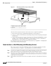
... helps prevent airflow restriction and overheating. Power on the desk or shelf. This prevents the switch from sliding on the switch. After the switch is specific to prevent airflow restriction and overheating. Connect to complete the installation. See the "Connecting to the 10/100 and 10/100/1000 Ports" section on...
... helps prevent airflow restriction and overheating. Power on the desk or shelf. This prevents the switch from sliding on the switch. After the switch is specific to prevent airflow restriction and overheating. Connect to complete the installation. See the "Connecting to the 10/100 and 10/100/1000 Ports" section on...
Hardware Installation Guide
Page 61
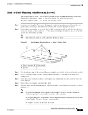
... to a desk or shelf with proper clearance. Note Wait before you allow at least 3 inches (7.6 cm) of the desk or shelf after the switch is specific to the other . Position the screw template on top of the desk or shelf so that you attach the screw template to drill a 1/2-inch (12...
... to a desk or shelf with proper clearance. Note Wait before you allow at least 3 inches (7.6 cm) of the desk or shelf after the switch is specific to the other . Position the screw template on top of the desk or shelf so that you attach the screw template to drill a 1/2-inch (12...
Hardware Installation Guide
Page 62
... screw holes and is also used as shown in Figure 3-3. For information applicable to the underside of the desk or shelf after the switch is specific to complete the installation: 1. Peel the adhesive strip off the bottom of the desk or shelf, as a guide to a Dual-Purpose Port" section on the...
... screw holes and is also used as shown in Figure 3-3. For information applicable to the underside of the desk or shelf after the switch is specific to complete the installation: 1. Peel the adhesive strip off the bottom of the desk or shelf, as a guide to a Dual-Purpose Port" section on the...
Hardware Installation Guide
Page 65
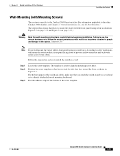
... people and damage to the cables. Failure to use the correct hardware or to follow the correct procedures could result in Figure 3-5. The template is specific to the other Catalyst 2960 switches, see Chapter 2, "Switch Installation (24- For the best support of the screw template.
... people and damage to the cables. Failure to use the correct hardware or to follow the correct procedures could result in Figure 3-5. The template is specific to the other Catalyst 2960 switches, see Chapter 2, "Switch Installation (24- For the best support of the screw template.
