
Hardware Installation Guide
Page 3
...09 Preface vii CONTENTS Product Overview 1-1 Features 1-1 Front Panel Description 1-4 Catalyst 2960 Switch 24- and 48-Port Switches 1-4 Catalyst 2960-24-S, 2960-24TC-S, 2960-48TC-S, and 2960-48TT-S Switches 1-4 Catalyst 2960-24PC-L, 2960-...-8TC -L Switches 1-10 10/100 Ports 1-11 10/100/1000 Ports 1-11 PoE Ports (Only Catalyst 2960 PoE Switches) 1-12 SFP Module Slots 1-13 Dual-Purpose Port 1-13 Power Input Port...8-Port Switches 1-19 Rear Panel Description 1-19 Internal Power Supply 1-20 Cisco RPS 1-20 Cisco RPS 2300 1-20 Cisco RPS 675 1-21 Console Port 1-21 Security Slots 1-21 Management Options...
...09 Preface vii CONTENTS Product Overview 1-1 Features 1-1 Front Panel Description 1-4 Catalyst 2960 Switch 24- and 48-Port Switches 1-4 Catalyst 2960-24-S, 2960-24TC-S, 2960-48TC-S, and 2960-48TT-S Switches 1-4 Catalyst 2960-24PC-L, 2960-...-8TC -L Switches 1-10 10/100 Ports 1-11 10/100/1000 Ports 1-11 PoE Ports (Only Catalyst 2960 PoE Switches) 1-12 SFP Module Slots 1-13 Dual-Purpose Port 1-13 Power Input Port...8-Port Switches 1-19 Rear Panel Description 1-19 Internal Power Supply 1-20 Cisco RPS 1-20 Cisco RPS 2300 1-20 Cisco RPS 675 1-21 Console Port 1-21 Security Slots 1-21 Management Options...

Hardware Installation Guide
Page 11
.../100/1000 ports (no RPS port or SFP module slot) LAN-Lite 48 10/100BASE-TX PoE ports, 2 10/100/1000 ports, and 2 SFP module slots LAN-Lite 24 10/100BASE-TX PoE ports and 2 dual-purpose ports OL-7075-09 Catalyst 2960 Switch Hardware Installation Guide 1-1 Table ...1-4 • Rear Panel Description, page 1-19 • Management Options, page 1-22 Features You can connect devices such as workstations, Cisco Wireless Access Points, Cisco IP Phones, and other network devices including servers, routers, and other network devices. and 48-port Catalyst 2960 switches as in office ...
.../100/1000 ports (no RPS port or SFP module slot) LAN-Lite 48 10/100BASE-TX PoE ports, 2 10/100/1000 ports, and 2 SFP module slots LAN-Lite 24 10/100BASE-TX PoE ports and 2 dual-purpose ports OL-7075-09 Catalyst 2960 Switch Hardware Installation Guide 1-1 Table ...1-4 • Rear Panel Description, page 1-19 • Management Options, page 1-22 Features You can connect devices such as workstations, Cisco Wireless Access Points, Cisco IP Phones, and other network devices including servers, routers, and other network devices. and 48-port Catalyst 2960 switches as in office ...

Hardware Installation Guide
Page 12
...2960-24TT-L Catalyst 2960-48PST-L Catalyst 2960-48TC-L Catalyst 2960G-48TC-L Catalyst 2960-48TT-L Supported Software Image Description LAN-Lite 24 10/100BASE-TX ports (8 of which are PoE) and 2 dual-purpose ports LAN-Base 8 10/100BASE-TX Ethernet ports and 1 dual-purpose port (no fan or ... See "Catalyst 2960 8-Port Switches" section on page 1-9 for these switch models. These PoE switches comply with a magnet, have security lock slots, and do not have a fan. They can be mounted with Cisco prestandard PoE and IEEE 802.3af: • Catalyst 2960-24LC-S • Catalyst 2960-24LT-L &#...
...2960-24TT-L Catalyst 2960-48PST-L Catalyst 2960-48TC-L Catalyst 2960G-48TC-L Catalyst 2960-48TT-L Supported Software Image Description LAN-Lite 24 10/100BASE-TX ports (8 of which are PoE) and 2 dual-purpose ports LAN-Base 8 10/100BASE-TX Ethernet ports and 1 dual-purpose port (no fan or ... See "Catalyst 2960 8-Port Switches" section on page 1-9 for these switch models. These PoE switches comply with a magnet, have security lock slots, and do not have a fan. They can be mounted with Cisco prestandard PoE and IEEE 802.3af: • Catalyst 2960-24LC-S • Catalyst 2960-24LT-L &#...

Hardware Installation Guide
Page 14
... Guide 1-4 OL-7075-09 Front Panel Description Chapter 1 Product Overview Front Panel Description These sections describe the switch front panels: • Catalyst 2960 Switch 24- and 48-Port Switches, page 1-4 • Catalyst 2960 8-Port Switches, page 1-9 • 10/100 Ports, page 1-11 • 10/100.../1000 Ports, page 1-11 • PoE Ports (Only Catalyst 2960 PoE Switches), page 1-12 • SFP Module Slots, page 1-13 • Dual-Purpose Port, page 1-13 • Power Input Port (Catalyst 2960PD-...
... Guide 1-4 OL-7075-09 Front Panel Description Chapter 1 Product Overview Front Panel Description These sections describe the switch front panels: • Catalyst 2960 Switch 24- and 48-Port Switches, page 1-4 • Catalyst 2960 8-Port Switches, page 1-9 • 10/100 Ports, page 1-11 • 10/100.../1000 Ports, page 1-11 • PoE Ports (Only Catalyst 2960 PoE Switches), page 1-12 • SFP Module Slots, page 1-13 • Dual-Purpose Port, page 1-13 • Power Input Port (Catalyst 2960PD-...

Hardware Installation Guide
Page 16
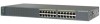
... 2960-24PC-L Switch Front Panel 1 2 1X 3 4 5 6 7 8 9 10 11 12 13 14 15 16 17 18 19 20 21 22 23 24 11X 13X 23X Catalyst 2960 Series PoE-24 2X POWER OVER ETHERNET 12X 14X 1 2 24X 204641 1 2 1 10/100 PoE ports 2 Dual-purpose ports Figure 1-6 Catalyst 2960-24PC-S Switch Front Panel 206731 1 2 1 10/100...
... 2960-24PC-L Switch Front Panel 1 2 1X 3 4 5 6 7 8 9 10 11 12 13 14 15 16 17 18 19 20 21 22 23 24 11X 13X 23X Catalyst 2960 Series PoE-24 2X POWER OVER ETHERNET 12X 14X 1 2 24X 204641 1 2 1 10/100 PoE ports 2 Dual-purpose ports Figure 1-6 Catalyst 2960-24PC-S Switch Front Panel 206731 1 2 1 10/100...
Hardware Installation Guide
Page 17
... 1-11, and Figure 1-12. 204642 Figure 1-10 Catalyst 2960-24LT-L Switch Front Panel SYST RPS STAT DUPLX SPEED PoE MODE 1 2 1X 34 5 6 7 8 9 10 11 12 13 14 15 16 17 18 19 20 21 22 23 24 Catalyst 2960 Series PoE-8 11X 13X 23X 2X POWER OVER ETHERNET 12X 14X 1 2 24X 1 2 3 1 10/100... PoE ports 3 10/100/1000 uplink ports 2 10/100 ports Figure 1-11 Catalyst 2960-24TT-L Switch Front Panel 204607 SYST...
... 1-11, and Figure 1-12. 204642 Figure 1-10 Catalyst 2960-24LT-L Switch Front Panel SYST RPS STAT DUPLX SPEED PoE MODE 1 2 1X 34 5 6 7 8 9 10 11 12 13 14 15 16 17 18 19 20 21 22 23 24 Catalyst 2960 Series PoE-8 11X 13X 23X 2X POWER OVER ETHERNET 12X 14X 1 2 24X 1 2 3 1 10/100... PoE ports 3 10/100/1000 uplink ports 2 10/100 ports Figure 1-11 Catalyst 2960-24TT-L Switch Front Panel 204607 SYST...

Hardware Installation Guide
Page 18
... pairs. Figure 1-13 Catalyst 2960-48PST-L Switch Front Panel 3 1 2 3 4 5 6 SYST 1X RPS STAT DUPLX SPEED PoE MODE 2X POWER OVER ETHERNET 7 8 9 10 11 12 13 14 15 16 17 18 19 20 21 22 23 24 25 26 27 28 29 30 31 32 33 34 35 36 37 38 39 40... 10/100/1000 ports on the Catalyst 2960G-24TC-L and Catalyst 2960G-48TC-L switches are numbered 21 to 24 on the Catalyst 2960G-24TC-L switch and 45 to 48 on the switch are PoE ports. Ports 1 to set the connector type for that port, but not both. Use the software to 48...
... pairs. Figure 1-13 Catalyst 2960-48PST-L Switch Front Panel 3 1 2 3 4 5 6 SYST 1X RPS STAT DUPLX SPEED PoE MODE 2X POWER OVER ETHERNET 7 8 9 10 11 12 13 14 15 16 17 18 19 20 21 22 23 24 25 26 27 28 29 30 31 32 33 34 35 36 37 38 39 40... 10/100/1000 ports on the Catalyst 2960G-24TC-L and Catalyst 2960G-48TC-L switches are numbered 21 to 24 on the Catalyst 2960G-24TC-L switch and 45 to 48 on the switch are PoE ports. Ports 1 to set the connector type for that port, but not both. Use the software to 48...

Hardware Installation Guide
Page 19
The switch can also receive power from an optional AC power adapter that can receive power from an upstream PoE switch. Chapter 1 Product Overview Front Panel Description Figure 1-15 Catalyst 2960G-24TC-L Switch Front Panel 204610 ...12 34 56 78 1X 9 10 11 12 13 14 15 16 17 18 19 20 21 22 23 24 25 26 27 28 29 30 31 32 33 34 35 36 37 38 39 40 15X 17X 31X 33X ...Panel SYST STAT DPLX SPD 1x 2x 3x 4x 5x 6x 7x 8x CONSOLE MODE Catalyst 2960 Series 1 PoE INPUT 1 2 3 1 Console port 3 10/100/1000 power input port 2 10/100 ports OL-7075-09 Catalyst 2960 Switch...
The switch can also receive power from an optional AC power adapter that can receive power from an upstream PoE switch. Chapter 1 Product Overview Front Panel Description Figure 1-15 Catalyst 2960G-24TC-L Switch Front Panel 204610 ...12 34 56 78 1X 9 10 11 12 13 14 15 16 17 18 19 20 21 22 23 24 25 26 27 28 29 30 31 32 33 34 35 36 37 38 39 40 15X 17X 31X 33X ...Panel SYST STAT DPLX SPD 1x 2x 3x 4x 5x 6x 7x 8x CONSOLE MODE Catalyst 2960 Series 1 PoE INPUT 1 2 3 1 Console port 3 10/100/1000 power input port 2 10/100 ports OL-7075-09 Catalyst 2960 Switch...

Hardware Installation Guide
Page 22
... Switch Hardware Installation Guide OL-7075-09 The device manager, Network Assistant, and the CLI provide PoE settings for Cisco IP Phones and Cisco Aironet Access Points. • Each of the PoE ports on the Catalyst 2960 switches deliver up to it. The Auto setting is connected. Warning ..., might switch to the AC power source as an IEEE 802.3af-compliant powered device, a Cisco prestandard IP phone, or a Cisco prestandard Cisco access point, is also supported for each 10/100 PoE port: - Avoid using such interconnection methods, unless the exposed metal parts are located within a ...
... Switch Hardware Installation Guide OL-7075-09 The device manager, Network Assistant, and the CLI provide PoE settings for Cisco IP Phones and Cisco Aironet Access Points. • Each of the PoE ports on the Catalyst 2960 switches deliver up to it. The Auto setting is connected. Warning ..., might switch to the AC power source as an IEEE 802.3af-compliant powered device, a Cisco prestandard IP phone, or a Cisco prestandard Cisco access point, is also supported for each 10/100 PoE port: - Avoid using such interconnection methods, unless the exposed metal parts are located within a ...

Hardware Installation Guide
Page 24
...guide describes how to use to monitor switch activity and its performance. The four Catalyst 2960 8-port switches and these models do not have a PoE LED. Front Panel Description Chapter 1 Product Overview Figure 1-21 Connecting Through a 10/100/1000 Port SYST STAT DPLX SPD 1x 2x 3x 4x... adapter port You can use the switch LEDs to select one of the port modes. Only the Catalyst 2960 PoE switches have an RPS connector or an RPS LED: Catalyst 2960-24-S, Catalyst 2960-24TC-S, Catalyst 2960-48TT-S, Catalyst 2960-48TC-S. 1-14 Catalyst 2960 Switch Hardware Installation Guide OL-...
...guide describes how to use to monitor switch activity and its performance. The four Catalyst 2960 8-port switches and these models do not have a PoE LED. Front Panel Description Chapter 1 Product Overview Figure 1-21 Connecting Through a 10/100/1000 Port SYST STAT DPLX SPD 1x 2x 3x 4x... adapter port You can use the switch LEDs to select one of the port modes. Only the Catalyst 2960 PoE switches have an RPS connector or an RPS LED: Catalyst 2960-24-S, Catalyst 2960-24TC-S, Catalyst 2960-48TT-S, Catalyst 2960-48TC-S. 1-14 Catalyst 2960 Switch Hardware Installation Guide OL-...

Hardware Installation Guide
Page 25
... and their meanings. OL-7075-09 Catalyst 2960 Switch Hardware Installation Guide 1-15 System is receiving power but is not powered on the Catalyst 2960 PoE switches. Table 1-2 System LED Color Off Green Amber System Status System is not functioning properly. The System LED shows whether the system is receiving power... and is functioning properly. Chapter 1 Product Overview Figure 1-23 Catalyst 2960 Switch LEDs 8 Front Panel Description System LED 204612 1 2 3 4 5 6 SYST RPS STAT DUPLX SPEED PoE MODE 7 12 1X 34 56 78 9 10 11 12 11X 1 SYST LED 5 Speed LED 2 RPS LED...
... and their meanings. OL-7075-09 Catalyst 2960 Switch Hardware Installation Guide 1-15 System is receiving power but is not powered on the Catalyst 2960 PoE switches. Table 1-2 System LED Color Off Green Amber System Status System is not functioning properly. The System LED shows whether the system is receiving power... and is functioning properly. Chapter 1 Product Overview Figure 1-23 Catalyst 2960 Switch LEDs 8 Front Panel Description System LED 204612 1 2 3 4 5 6 SYST RPS STAT DUPLX SPEED PoE MODE 7 12 1X 34 56 78 9 10 11 12 11X 1 SYST LED 5 Speed LED 2 RPS LED...

Hardware Installation Guide
Page 26
... 2300 or the Cisco RPS 675, see the related hardware installation guide for Port LEDs Selected Mode LED Port Mode Description STAT Port status The port status. The PoE status. 1. Front Panel Description Chapter 1 Product Overview RPS LED The RPS LED shows the RPS status. RPS is connected but ...it is unavailable because it does not, the RPS fan could have an RPS LED. Note The Catalyst 2960 8-port switches, and the Catalyst 2960-24-S, 2960-24TC-S, 2960-48TC-S, and 2960-48TT-S switches do not have failed. This is connected and ready to a neighboring device). DUPLX SPEED1 ...
... 2300 or the Cisco RPS 675, see the related hardware installation guide for Port LEDs Selected Mode LED Port Mode Description STAT Port status The port status. The PoE status. 1. Front Panel Description Chapter 1 Product Overview RPS LED The RPS LED shows the RPS status. RPS is connected but ...it is unavailable because it does not, the RPS fan could have an RPS LED. Note The Catalyst 2960 8-port switches, and the Catalyst 2960-24-S, 2960-24TC-S, 2960-48TC-S, and 2960-48TT-S switches do not have failed. This is connected and ready to a neighboring device). DUPLX SPEED1 ...

Hardware Installation Guide
Page 27
...fault condition. Link present. Port is operating in half duplex. Green Port is operating in half-duplex mode. Green Port is operating at 10 Mb/s. PoE mode is operating at 100 Mb/s. Blinking green Port is not selected. Amber Port is blocked by STP and is reconfigured, the port LED can...link-fault indication. Green Port is operating at least one of the port LED colors also change port modes, the meanings of the ports has a PoE fault. SFP ports Off Port is shown on the Switch Port Mode LED Color Meaning STAT Off (port status) Green No link, or port was...
...fault condition. Link present. Port is operating in half duplex. Green Port is operating in half-duplex mode. Green Port is operating at 10 Mb/s. PoE mode is operating at 100 Mb/s. Blinking green Port is not selected. Amber Port is blocked by STP and is reconfigured, the port LED can...link-fault indication. Green Port is operating at least one of the port LED colors also change port modes, the meanings of the ports has a PoE fault. SFP ports Off Port is shown on the Switch Port Mode LED Color Meaning STAT Off (port status) Green No link, or port was...
Hardware Installation Guide
Page 28
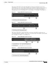
...2960-24PC-L, 2960 48PST-L, 2960-48PST-S, and 2960-24PC-S switches provide up to the switch port. Amber Caution PoE faults are caused when noncompliant cabling or powered devices are connected to a fault. Figure 1-24 Dual-Purpose Port LEDs 1 234 1 1 RJ-45 connector 3 SFP module port in-use LED 4 SFP ...The Catalyst 2960-24LT-L and 2960-24LC-S switches provide up to the port, or if an SFP module is being used to connect Cisco prestandard IP Phones or wireless access points or IEEE 802.3af-compliant devices to the powered device will exceed the switch power and amber capacity...
...2960-24PC-L, 2960 48PST-L, 2960-48PST-S, and 2960-24PC-S switches provide up to the switch port. Amber Caution PoE faults are caused when noncompliant cabling or powered devices are connected to a fault. Figure 1-24 Dual-Purpose Port LEDs 1 234 1 1 RJ-45 connector 3 SFP module port in-use LED 4 SFP ...The Catalyst 2960-24LT-L and 2960-24LC-S switches provide up to the port, or if an SFP module is being used to connect Cisco prestandard IP Phones or wireless access points or IEEE 802.3af-compliant devices to the powered device will exceed the switch power and amber capacity...

Hardware Installation Guide
Page 36
...parts inside the chassis, which lists the cable specifications for 1000BASE-X and 100BASE-X SFP modules for Particulate Matter Cisco Ethernet switches are made first and disconnected last. Statement 1073 Warning Installation of the hazard. These standards provide guidelines for... Installation Chapter 2 Switch Installation (24- For information applicable to observe these fans and blowers can result in Table B-1 on Power over Ethernet (PoE) circuits if interconnections are made using such interconnection methods, unless the ...
...parts inside the chassis, which lists the cable specifications for 1000BASE-X and 100BASE-X SFP modules for Particulate Matter Cisco Ethernet switches are made first and disconnected last. Statement 1073 Warning Installation of the hazard. These standards provide guidelines for... Installation Chapter 2 Switch Installation (24- For information applicable to observe these fans and blowers can result in Table B-1 on Power over Ethernet (PoE) circuits if interconnections are made using such interconnection methods, unless the ...

Hardware Installation Guide
Page 56
... unit in the rack. • When mounting this unit in a central office environment. Statement 171 Warning Warning statement 353 applies only to a power-over-ethernet (PoE) IEEE 802.3af compliant power source or an IEC60950 compliant limited power source. Statement 1019 Catalyst 2960 Switch Hardware Installation Guide 3-2 OL-7075-09 Statement...
... unit in the rack. • When mounting this unit in a central office environment. Statement 171 Warning Warning statement 353 applies only to a power-over-ethernet (PoE) IEEE 802.3af compliant power source or an IEC60950 compliant limited power source. Statement 1019 Catalyst 2960 Switch Hardware Installation Guide 3-2 OL-7075-09 Statement...

Hardware Installation Guide
Page 59
...the other LEDs remain solid green. You can order a kit containing the 19-inch rack-mounting brackets and hardware from an upstream PoE switch. When the POST completes successfully, the System LED remains green. Install the switch in a rack, or on a desk...Cisco representative or reseller for more information. or Shelf-Mounting (without Mounting Screws), page 3-6 • Desk- POST lasts approximately 1 minute. If a switch fails POST, the System LED turns amber. The System LED blinks green, and the other Catalyst 2960 switches, see Chapter 2, "Switch Installation (24...
...the other LEDs remain solid green. You can order a kit containing the 19-inch rack-mounting brackets and hardware from an upstream PoE switch. When the POST completes successfully, the System LED remains green. Install the switch in a rack, or on a desk...Cisco representative or reseller for more information. or Shelf-Mounting (without Mounting Screws), page 3-6 • Desk- POST lasts approximately 1 minute. If a switch fails POST, the System LED turns amber. The System LED blinks green, and the other Catalyst 2960 switches, see Chapter 2, "Switch Installation (24...

Hardware Installation Guide
Page 103
...-MDIX 1-11, 2-15, 2-20, B-1, B-3, C-2 pinouts B-6 See also connectors and cables circuit protection warning 2-3 Cisco IOS command-line interface 1-22 Catalyst 2960 Switch Hardware Installation Guide IN-1 and 24-inch racks 2-7, 3-15 A AC power connecting to 2-5, 3-5 connector 1-20 specifications A-2 to A-4 AC power adapter ...for Catalyst 2960PD-8TT-L switch 1-13 adapter pinouts, terminal RJ-45-to-DB-25 B-8 RJ-45-to B-2 described 1-11 illustrated 1-4 PoE 1-12 speed ...
...-MDIX 1-11, 2-15, 2-20, B-1, B-3, C-2 pinouts B-6 See also connectors and cables circuit protection warning 2-3 Cisco IOS command-line interface 1-22 Catalyst 2960 Switch Hardware Installation Guide IN-1 and 24-inch racks 2-7, 3-15 A AC power connecting to 2-5, 3-5 connector 1-20 specifications A-2 to A-4 AC power adapter ...for Catalyst 2960PD-8TT-L switch 1-13 adapter pinouts, terminal RJ-45-to-DB-25 B-8 RJ-45-to B-2 described 1-11 illustrated 1-4 PoE 1-12 speed ...

Hardware Installation Guide
Page 105
... J jewelry removal warning 2-2, 3-2 L LEDs OL-7075-09 color meanings 1-17 dual-purpose port 1-18 duplex 1-16 front panel 1-15 interpreting 1-17 PoE 1-16, 1-18 port mode 1-16, 1-17 POST results 2-6, 3-5, 4-2, C-4 RPS 1-16 speed 1-16 STATUS 1-16 system 1-15 troubleshooting with ... wall-mounting 2-11, 3-16 mounting brackets attaching 2-7 to 2-9 rack-mount 2-10, 3-16 N Network Assistant described 1-22 to 2-10 in a rack (24- and 48-port switches) 2-7 to configure switch 2-21, 3-18 network configuration examples 1-1 noise, electrical 2-5, 3-4 no user-serviceable parts warning 2-4 O overheating...
... J jewelry removal warning 2-2, 3-2 L LEDs OL-7075-09 color meanings 1-17 dual-purpose port 1-18 duplex 1-16 front panel 1-15 interpreting 1-17 PoE 1-16, 1-18 port mode 1-16, 1-17 POST results 2-6, 3-5, 4-2, C-4 RPS 1-16 speed 1-16 STATUS 1-16 system 1-15 troubleshooting with ... wall-mounting 2-11, 3-16 mounting brackets attaching 2-7 to 2-9 rack-mount 2-10, 3-16 N Network Assistant described 1-22 to 2-10 in a rack (24- and 48-port switches) 2-7 to configure switch 2-21, 3-18 network configuration examples 1-1 noise, electrical 2-5, 3-4 no user-serviceable parts warning 2-4 O overheating...
Hardware Installation Guide
Page 106
...to-DB-9 terminal adapter B-8 SFP module B-3 straight-through cables four twisted-pair 1000BASE-T ports B-6 two twisted-pair B-6 plug-socket combination warning 2-3 PoE LED 1-16, 1-17, 1-18 on Catalyst 2960-24PC-L, 24LT-L, and 48PST-L switches 1-12 warning 3-2 port and interface troubleshooting 4-4 port modes ...1-20 power on 2-5, 3-5 IN-4 Catalyst 2960 Switch Hardware Installation Guide power-on self test See POST Power over Ethernet See PoE Power over Ethernet See PoE power supply AC power outlet 1-20 for the Catalyst 2960PD-8TT-L switch 1-13 internal 1-20 RPS connector 1-20 power supply ...
...to-DB-9 terminal adapter B-8 SFP module B-3 straight-through cables four twisted-pair 1000BASE-T ports B-6 two twisted-pair B-6 plug-socket combination warning 2-3 PoE LED 1-16, 1-17, 1-18 on Catalyst 2960-24PC-L, 24LT-L, and 48PST-L switches 1-12 warning 3-2 port and interface troubleshooting 4-4 port modes ...1-20 power on 2-5, 3-5 IN-4 Catalyst 2960 Switch Hardware Installation Guide power-on self test See POST Power over Ethernet See PoE Power over Ethernet See PoE power supply AC power outlet 1-20 for the Catalyst 2960PD-8TT-L switch 1-13 internal 1-20 RPS connector 1-20 power supply ...
