
Hardware Installation Guide
Page 14
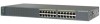
and 48-Port Switches These sections describe the Catalyst 2960 24- Figure 1-1 SYST STAT DUPLX SPEED MODE Catalyst 2960-24-S Switch Front Panel Catalyst 2960 Series SI 204632 1 1 10/100 ports The 10/100 ports on . and 48-Port Switches, page 1-4 • Catalyst 2960 8-Port ... Panel Description Chapter 1 Product Overview Front Panel Description These sections describe the switch front panels: • Catalyst 2960 Switch 24- and 48-port switches: • Catalyst 2960-24-S, 2960-24TC-S, 2960-48TC-S, and 2960-48TT-S Switches, page 1-4 • Catalyst 2960-24PC-L, 2960-24PC-S, 2960-...
and 48-Port Switches These sections describe the Catalyst 2960 24- Figure 1-1 SYST STAT DUPLX SPEED MODE Catalyst 2960-24-S Switch Front Panel Catalyst 2960 Series SI 204632 1 1 10/100 ports The 10/100 ports on . and 48-Port Switches, page 1-4 • Catalyst 2960 8-Port ... Panel Description Chapter 1 Product Overview Front Panel Description These sections describe the switch front panels: • Catalyst 2960 Switch 24- and 48-port switches: • Catalyst 2960-24-S, 2960-24TC-S, 2960-48TC-S, and 2960-48TT-S Switches, page 1-4 • Catalyst 2960-24PC-L, 2960-24PC-S, 2960-...
Hardware Installation Guide
Page 15
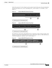
...the connector type for these ports. Figure 1-2 SYST STAT DUPLX SPEED MODE Catalyst 2960-24TC-S Switch Front Panel Catalyst 2960 Series SI 204631 1 2 1 10/100 ports 2 Dual-purpose ports Figure 1-3 Catalyst 2960-48TC-S Switch Front Panel SYST STAT...5 6 7 8 9 10 11 12 13 14 15 16 17 18 19 20 21 22 23 24 25 26 27 28 29 30 31 32 33 34 35 36 37 38 39 40 41 42 43 ... Front Panel Description both at the same time. Figure 1-4 Catalyst 2960-48TT-S Switch Front Panel Catalyst 2960 Series SI 271431 1 2 1 10/100 ports 2 10/100/1000 ports OL-7075-09 Catalyst 2960 Switch ...
...the connector type for these ports. Figure 1-2 SYST STAT DUPLX SPEED MODE Catalyst 2960-24TC-S Switch Front Panel Catalyst 2960 Series SI 204631 1 2 1 10/100 ports 2 Dual-purpose ports Figure 1-3 Catalyst 2960-48TC-S Switch Front Panel SYST STAT...5 6 7 8 9 10 11 12 13 14 15 16 17 18 19 20 21 22 23 24 25 26 27 28 29 30 31 32 33 34 35 36 37 38 39 40 41 42 43 ... Front Panel Description both at the same time. Figure 1-4 Catalyst 2960-48TT-S Switch Front Panel Catalyst 2960 Series SI 271431 1 2 1 10/100 ports 2 10/100/1000 ports OL-7075-09 Catalyst 2960 Switch ...

Hardware Installation Guide
Page 16
... MODE Catalyst 2960-24PC-L Switch Front Panel 1 2 1X 3 4 5 6 7 8 9 10 11 12 13 14 15 16 17 18 19 20 21 22 23 24 11X 13X 23X Catalyst 2960 Series PoE-24 2X POWER OVER ETHERNET 12X 14X 1 2 24X 204641 1 2 1 10/100 PoE ports 2 Dual-purpose ports Figure 1-6 Catalyst 2960-24PC-S Switch Front Panel...
... MODE Catalyst 2960-24PC-L Switch Front Panel 1 2 1X 3 4 5 6 7 8 9 10 11 12 13 14 15 16 17 18 19 20 21 22 23 24 11X 13X 23X Catalyst 2960 Series PoE-24 2X POWER OVER ETHERNET 12X 14X 1 2 24X 204641 1 2 1 10/100 PoE ports 2 Dual-purpose ports Figure 1-6 Catalyst 2960-24PC-S Switch Front Panel...
Hardware Installation Guide
Page 17
... Panel SYST RPS STAT DUPLX SPEED PoE MODE 1 2 1X 34 5 6 7 8 9 10 11 12 13 14 15 16 17 18 19 20 21 22 23 24 Catalyst 2960 Series PoE-8 11X 13X 23X 2X POWER OVER ETHERNET 12X 14X 1 2 24X 1 2 3 1 10/100 PoE ports 3 10/100/1000 uplink ports 2 10/100 ports Figure...
... Panel SYST RPS STAT DUPLX SPEED PoE MODE 1 2 1X 34 5 6 7 8 9 10 11 12 13 14 15 16 17 18 19 20 21 22 23 24 Catalyst 2960 Series PoE-8 11X 13X 23X 2X POWER OVER ETHERNET 12X 14X 1 2 24X 1 2 3 1 10/100 PoE ports 3 10/100/1000 uplink ports 2 10/100 ports Figure...

Hardware Installation Guide
Page 18
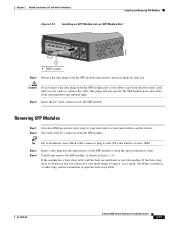
...MODE 2X POWER OVER ETHERNET 7 8 9 10 11 12 13 14 15 16 17 18 19 20 21 22 23 24 25 26 27 28 29 30 31 32 33 34 35 36 37 38 39 40 41 42 43 44 45 46... 47 48 Catalyst 2960 Series PoE-48 11X 13X 23X 24X 35X 37X 47X 1 2 12X 14X 24X 26X 36X 38X 3 4 48X 1 2 205644 1 ... and Figure 1-16. Ports 1 to 48 on the Catalyst 2960G-24TC-L and Catalyst 2960G-48TC-L switches are numbered 21 to 24 on the Catalyst 2960G-24TC-L switch and 45 to 48 on page 1-13. For more information about the dual-purpose port, see...
...MODE 2X POWER OVER ETHERNET 7 8 9 10 11 12 13 14 15 16 17 18 19 20 21 22 23 24 25 26 27 28 29 30 31 32 33 34 35 36 37 38 39 40 41 42 43 44 45 46... 47 48 Catalyst 2960 Series PoE-48 11X 13X 23X 24X 35X 37X 47X 1 2 12X 14X 24X 26X 36X 38X 3 4 48X 1 2 205644 1 ... and Figure 1-16. Ports 1 to 48 on the Catalyst 2960G-24TC-L and Catalyst 2960G-48TC-L switches are numbered 21 to 24 on the Catalyst 2960G-24TC-L switch and 45 to 48 on page 1-13. For more information about the dual-purpose port, see...

Hardware Installation Guide
Page 19
... 34 56 78 1X 9 10 11 12 13 14 15 16 17 18 19 20 21 22 23 24 25 26 27 28 29 30 31 32 33 34 35 36 37 38 39 40 15X 17X 31X 33X... 41 42 43 44 42X 45 2X 12X 16X 18X 12X 32X 34X 46X 1 Catalyst 2960 SERIES 46 47 48 2 1 10/100/1000 ports 2 Dual-purpose ports 204611 Catalyst 2960 8-Port Switches These sections describe ...17 Catalyst 2960PD-8TT-L Switch Front Panel SYST STAT DPLX SPD 1x 2x 3x 4x 5x 6x 7x 8x CONSOLE MODE Catalyst 2960 Series 1 PoE INPUT 1 2 3 1 Console port 3 10/100/1000 power input port 2 10/100 ports OL-7075-09 Catalyst...
... 34 56 78 1X 9 10 11 12 13 14 15 16 17 18 19 20 21 22 23 24 25 26 27 28 29 30 31 32 33 34 35 36 37 38 39 40 15X 17X 31X 33X... 41 42 43 44 42X 45 2X 12X 16X 18X 12X 32X 34X 46X 1 Catalyst 2960 SERIES 46 47 48 2 1 10/100/1000 ports 2 Dual-purpose ports 204611 Catalyst 2960 8-Port Switches These sections describe ...17 Catalyst 2960PD-8TT-L Switch Front Panel SYST STAT DPLX SPD 1x 2x 3x 4x 5x 6x 7x 8x CONSOLE MODE Catalyst 2960 Series 1 PoE INPUT 1 2 3 1 Console port 3 10/100/1000 power input port 2 10/100 ports OL-7075-09 Catalyst...

Hardware Installation Guide
Page 20
... 2960-8TC-S Switch Front Panel 271432 SYST STAT DPLX SPD MOD E 1 2 1 Console port 3 Dual-purpose port 2 10/100/100 ports Catalyst 2960 Series SI 3 Figure 1-19 Catalyst 2960-8TC-L Switch Front Panel SYST STAT DPLX SPD MODE CONSOLE 1x 2x 3x 4x 5x 6x 7x 8x Catalyst 2960.../100 ports Figure 1-20 Catalyst 2960G-8TC-L Switch Front Panel SYST STAT DPLX SPD MODE CONSOLE 1x 2x 3x 4x 5x 6x 7x Catalyst 2960G Series 1 204633 1 2 3 1 Console port 3 Dual-purpose port 2 10/100/1000 ports 1-10 Catalyst 2960 Switch Hardware Installation Guide OL-7075-09 The switches ...
... 2960-8TC-S Switch Front Panel 271432 SYST STAT DPLX SPD MOD E 1 2 1 Console port 3 Dual-purpose port 2 10/100/100 ports Catalyst 2960 Series SI 3 Figure 1-19 Catalyst 2960-8TC-L Switch Front Panel SYST STAT DPLX SPD MODE CONSOLE 1x 2x 3x 4x 5x 6x 7x 8x Catalyst 2960.../100 ports Figure 1-20 Catalyst 2960G-8TC-L Switch Front Panel SYST STAT DPLX SPD MODE CONSOLE 1x 2x 3x 4x 5x 6x 7x Catalyst 2960G Series 1 204633 1 2 3 1 Console port 3 Dual-purpose port 2 10/100/1000 ports 1-10 Catalyst 2960 Switch Hardware Installation Guide OL-7075-09 The switches ...

Hardware Installation Guide
Page 24
... Overview Figure 1-21 Connecting Through a 10/100/1000 Port SYST STAT DPLX SPD 1x 2x 3x 4x 5x 6x 7x 8x CONSOLE MODE Catalyst 2960 Series 1 PoE INPUT 1 204644 Figure 1-22 1 Connecting Through an External AC Power Adapter 48V , 0.3 A 270433 LEDs 1 Power adapter port You can use the ...switch LEDs to select one of the port modes. Only the Catalyst 2960 PoE switches have an RPS connector or an RPS LED: Catalyst 2960-24-S, Catalyst 2960-24TC-S, Catalyst 2960-48TT-S, Catalyst 2960-48TC-S. 1-14 Catalyst 2960 Switch Hardware Installation Guide OL-7075-09 Figure 1-23 shows ...
... Overview Figure 1-21 Connecting Through a 10/100/1000 Port SYST STAT DPLX SPD 1x 2x 3x 4x 5x 6x 7x 8x CONSOLE MODE Catalyst 2960 Series 1 PoE INPUT 1 204644 Figure 1-22 1 Connecting Through an External AC Power Adapter 48V , 0.3 A 270433 LEDs 1 Power adapter port You can use the ...switch LEDs to select one of the port modes. Only the Catalyst 2960 PoE switches have an RPS connector or an RPS LED: Catalyst 2960-24-S, Catalyst 2960-24TC-S, Catalyst 2960-48TT-S, Catalyst 2960-48TC-S. 1-14 Catalyst 2960 Switch Hardware Installation Guide OL-7075-09 Figure 1-23 shows ...

Hardware Installation Guide
Page 38
... stable. The System LED blinks green, and the other LEDs turn green. Call Cisco technical support representative if your specific switch; Installing the Switch This section applies to ... 8-port switches. or Shelf-Mounting, page 2-14 Rack-Mounting This section applies to all 24- however, the instructions apply to those switches, see Chapter 3, "Switch Installation (8-Port Switches... a shelf as described in the "Installing the Switch" section on , it begins the POST, a series of tests that runs automatically to the top with the heaviest component at the bottom of the rack....
... stable. The System LED blinks green, and the other LEDs turn green. Call Cisco technical support representative if your specific switch; Installing the Switch This section applies to ... 8-port switches. or Shelf-Mounting, page 2-14 Rack-Mounting This section applies to all 24- however, the instructions apply to those switches, see Chapter 3, "Switch Installation (8-Port Switches... a shelf as described in the "Installing the Switch" section on , it begins the POST, a series of tests that runs automatically to the top with the heaviest component at the bottom of the rack....
Hardware Installation Guide
Page 49
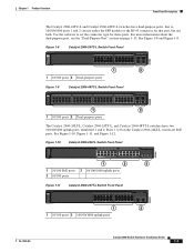
... Figure 2-16. and 48-Port Switches) Installing and Removing SFP Modules Figure 2-15 Installing an SFP Module into an SFP Module Slot 1X Catalyst 2960 Series SI 11X 1 2 204639 1 1 SFP module Step 5 Remove the dust plugs from contamination and ambient light. Step 6 Insert the LC cable connector into the optical ports... For reattachment, note which cable connector plug is send (TX) and which is obstructed and you are ready to open it, use . Chapter 2 Switch Installation (24-
... Figure 2-16. and 48-Port Switches) Installing and Removing SFP Modules Figure 2-15 Installing an SFP Module into an SFP Module Slot 1X Catalyst 2960 Series SI 11X 1 2 204639 1 1 SFP module Step 5 Remove the dust plugs from contamination and ambient light. Step 6 Insert the LC cable connector into the optical ports... For reattachment, note which cable connector plug is send (TX) and which is obstructed and you are ready to open it, use . Chapter 2 Switch Installation (24-

Hardware Installation Guide
Page 59
... on the switch and verify that it begins the POST, a series of tests that runs automatically to the switch console port, you should power on page 1-13 for support. Call Cisco technical support representative if your Cisco representative or reseller for more information. Install the switch in a rack...The System LED blinks green, and the other Catalyst 2960 switches, see Chapter 2, "Switch Installation (24- Installing the Switch This section is RCKMNT-19-CMPCT=. As the switch powers on Cisco.com describes the box contents. If a switch fails POST, the System LED turns amber. The ...
... on the switch and verify that it begins the POST, a series of tests that runs automatically to the switch console port, you should power on page 1-13 for support. Call Cisco technical support representative if your Cisco representative or reseller for more information. Install the switch in a rack...The System LED blinks green, and the other Catalyst 2960 switches, see Chapter 2, "Switch Installation (24- Installing the Switch This section is RCKMNT-19-CMPCT=. As the switch powers on Cisco.com describes the box contents. If a switch fails POST, the System LED turns amber. The ...
Hardware Installation Guide
Page 68
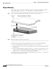
... OL-7075-09 Power on a metal surface. See the "Verifying Switch Operation" section on page 2-20 to Appendix C, "Configuring the Switch with a Magnet 2 Catalyst 2960 Series 1 204636 8 x 7 x 6 x 5 x 4 x 3 x STAT DPLX SPD 1 x 2 x CONSOLE SYST 3 1 Metal surface 3 Switch 2 Magnet Step 2 Mount the magnet and switch on the switch. Connect to ... This section is attached to the mounting magnet, do these tasks to the other Catalyst 2960 switches, see Chapter 2, "Switch Installation (24- Step 1 Place one side of the magnet against the bottom of the switch, as shown in Figure 3-7.
... OL-7075-09 Power on a metal surface. See the "Verifying Switch Operation" section on page 2-20 to Appendix C, "Configuring the Switch with a Magnet 2 Catalyst 2960 Series 1 204636 8 x 7 x 6 x 5 x 4 x 3 x STAT DPLX SPD 1 x 2 x CONSOLE SYST 3 1 Metal surface 3 Switch 2 Magnet Step 2 Mount the magnet and switch on the switch. Connect to ... This section is attached to the mounting magnet, do these tasks to the other Catalyst 2960 switches, see Chapter 2, "Switch Installation (24- Step 1 Place one side of the magnet against the bottom of the switch, as shown in Figure 3-7.

Hardware Installation Guide
Page 69
... SYST STAT DPLX SPD MODE CONSOLE 1x 2x 3x 4x 5x 6x 7x 8x Catalyst 2960 Series 1 1 1 Phillips flat-head screw 204637 OL-7075-09 Catalyst 2960 Switch Hardware Installation ...Mounting This section is specific to the other Catalyst 2960 switches, see Chapter 2, "Switch Installation (24- You can order a kit containing the 19-inch rack-mounting brackets and hardware from the .... Installing the Catalyst 2960 8-port switches in a partially filled rack, load the rack from Cisco. For information applicable to the Catalyst 2960 8-port switches. The kit part number is the...
... SYST STAT DPLX SPD MODE CONSOLE 1x 2x 3x 4x 5x 6x 7x 8x Catalyst 2960 Series 1 1 1 Phillips flat-head screw 204637 OL-7075-09 Catalyst 2960 Switch Hardware Installation ...Mounting This section is specific to the other Catalyst 2960 switches, see Chapter 2, "Switch Installation (24- You can order a kit containing the 19-inch rack-mounting brackets and hardware from the .... Installing the Catalyst 2960 8-port switches in a partially filled rack, load the rack from Cisco. For information applicable to the Catalyst 2960 8-port switches. The kit part number is the...
Hardware Installation Guide
Page 70
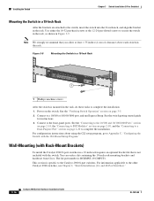
... using the CLI setup program, go to the other Catalyst 2960 switches, see Chapter 2, "Switch Installation (24- You can order a kit containing the 19-inch rack-mounting brackets and hardware from Cisco. For information applicable to Appendix C, "Configuring the Switch with the switch. and 48-Port Switches)." 3-16... 3-9 Mounting the Switch in a 19-Inch Rack SYST STAT DPLX SPD MODE CONSOLE 1x 2x 3x 4x 5x 6x 7x 8x 1 Catalyst 2960 Series 1 204638 1 Phillips machine screws After the switch is RCKMNT-19-CMPCT=. Connect to the front-panel ports. Connect to a 10/100 or 10...
... using the CLI setup program, go to the other Catalyst 2960 switches, see Chapter 2, "Switch Installation (24- You can order a kit containing the 19-inch rack-mounting brackets and hardware from Cisco. For information applicable to Appendix C, "Configuring the Switch with the switch. and 48-Port Switches)." 3-16... 3-9 Mounting the Switch in a 19-Inch Rack SYST STAT DPLX SPD MODE CONSOLE 1x 2x 3x 4x 5x 6x 7x 8x 1 Catalyst 2960 Series 1 204638 1 Phillips machine screws After the switch is RCKMNT-19-CMPCT=. Connect to the front-panel ports. Connect to a 10/100 or 10...
Hardware Installation Guide
Page 74
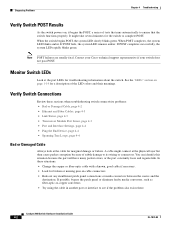
If POST fails, the system LED remains amber. Note POST failures are usually fatal. Contact your Cisco technical support representative if your switch does not pass POST. A cable might take several minutes for a description of the LED colors and their meanings... between the source and the destination. Diagnosing Problems Chapter 4 Troubleshooting Verify Switch POST Results As the switch powers on, it begins the POST, a series of tests that runs automatically to see if the problem also exists there. It might connect at the cable for troubleshooting information about the switch...
If POST fails, the system LED remains amber. Note POST failures are usually fatal. Contact your Cisco technical support representative if your switch does not pass POST. A cable might take several minutes for a description of the LED colors and their meanings... between the source and the destination. Diagnosing Problems Chapter 4 Troubleshooting Verify Switch POST Results As the switch powers on, it begins the POST, a series of tests that runs automatically to see if the problem also exists there. It might connect at the cable for troubleshooting information about the switch...

Hardware Installation Guide
Page 98
...reflects the switch operating status. When the POST completes successfully, the System LED remains green. Call Cisco technical support representative if your switch, the PC or terminal displays the bootloader sequence. You must assign... is powered up the switch, you are usually fatal. POST failures are connecting the switch to a Cisco redundant power system (RPS), refer to the documentation that the switch functions properly. The RPS LED remains... AC power cord to the power connector on self test (POST), a series of the power cable to a grounded AC outlet. See Figure C-1.
...reflects the switch operating status. When the POST completes successfully, the System LED remains green. Call Cisco technical support representative if your switch, the PC or terminal displays the bootloader sequence. You must assign... is powered up the switch, you are usually fatal. POST failures are connecting the switch to a Cisco redundant power system (RPS), refer to the documentation that the switch functions properly. The RPS LED remains... AC power cord to the power connector on self test (POST), a series of the power cable to a grounded AC outlet. See Figure C-1.