Hardware Installation Guide
Page 2
...is no longer complying with FCC requirements for a Class B digital device in accordance with radio and television reception. These specifications are designed to provide reasonable protection against harmful interference when the equipment is for a Class A digital device, pursuant to...University of its peripheral devices. If it may result in a commercial environment. Modifying the equipment without Cisco's written authorization may cause interference with the specifications in a particular installation. could void the FCC approval and negate your own expense. All rights ...
...is no longer complying with FCC requirements for a Class B digital device in accordance with radio and television reception. These specifications are designed to provide reasonable protection against harmful interference when the equipment is for a Class A digital device, pursuant to...University of its peripheral devices. If it may result in a commercial environment. Modifying the equipment without Cisco's written authorization may cause interference with the specifications in a particular installation. could void the FCC approval and negate your own expense. All rights ...
Hardware Installation Guide
Page 6
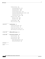
... Where to Go from Here 2-22 Troubleshooting 3-1 Problems During First Startup 3-2 Problems After First Startup 3-3 Problems After Router Is Running 3-5 When Contacting Your Cisco Reseller 3-7 ISDN and IDSL Concepts A-1 Specifications and Cables B-1 System Specifications B-1 Port Connector Pinouts B-2 Cabling Specifications B-6 Ethernet Cable Specifications B-7 Maximum Cable Distances B-7 Cisco 800 Series Routers Hardware Installation Guide vi 78-5373-04
... Where to Go from Here 2-22 Troubleshooting 3-1 Problems During First Startup 3-2 Problems After First Startup 3-3 Problems After Router Is Running 3-5 When Contacting Your Cisco Reseller 3-7 ISDN and IDSL Concepts A-1 Specifications and Cables B-1 System Specifications B-1 Port Connector Pinouts B-2 Cabling Specifications B-6 Ethernet Cable Specifications B-7 Maximum Cable Distances B-7 Cisco 800 Series Routers Hardware Installation Guide vi 78-5373-04
Hardware Installation Guide
Page 7
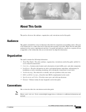
...levels of router LEDs, ports, and other components. • Installation-Provides information on the router. • Specifications and Cables-Provides router, port, and cable specifications. • Glossary-Defines technical terms frequently used in this guide. Where relevant, this guide explains how the ...is usually in this guide. Conceptual information is to connect the router to additional information and material. 78-5373-04 Cisco 800 Series Routers Hardware Installation Guide vii Conventions This section describes the conventions used in a separate section or appendix so...
...levels of router LEDs, ports, and other components. • Installation-Provides information on the router. • Specifications and Cables-Provides router, port, and cable specifications. • Glossary-Defines technical terms frequently used in this guide. Where relevant, this guide explains how the ...is usually in this guide. Conceptual information is to connect the router to additional information and material. 78-5373-04 Cisco 800 Series Routers Hardware Installation Guide vii Conventions This section describes the conventions used in a separate section or appendix so...

Hardware Installation Guide
Page 26
...your own cable, see the "Cabling Specifications" section in . Connecting the port to this appendix does not provide specifications for use with red ISDN U cable • Product documentation Preinstallation Activities Before you begin installing your Cisco 800 series router, perform the following steps...from your router came in Appendix B, "Specifications and Cables." If any of suitability with your router. If this type of suitability ( ) appears above a port, you have a Cisco 801 or Cisco 803 router, do the following: Cisco 800 Series Routers Hardware Installation Guide 2-4...
...your own cable, see the "Cabling Specifications" section in . Connecting the port to this appendix does not provide specifications for use with red ISDN U cable • Product documentation Preinstallation Activities Before you begin installing your Cisco 800 series router, perform the following steps...from your router came in Appendix B, "Specifications and Cables." If any of suitability with your router. If this type of suitability ( ) appears above a port, you have a Cisco 801 or Cisco 803 router, do the following: Cisco 800 Series Routers Hardware Installation Guide 2-4...
Hardware Installation Guide
Page 27
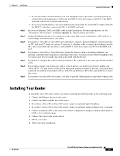
...cable. Gather the Ethernet devices to be connected to connect each device (usually this cable is provided with the device). If you have a Cisco 803 or Cisco 804 router, connect an optional analog telephone, fax, or modem. 5. You must also provide the telephone cable to the router: hub,...for external NT1 vendors. Installing Your Router To install the Cisco 800 series routers, you must provide an NT1 with 8-mm drill bit) to the router. 2. For more information, see the "Maximum Cable Distances" section in Appendix B, "Specifications and Cables." If you are outside of Ethernet, ISDN,...
...cable. Gather the Ethernet devices to be connected to connect each device (usually this cable is provided with the device). If you have a Cisco 803 or Cisco 804 router, connect an optional analog telephone, fax, or modem. 5. You must also provide the telephone cable to the router: hub,...for external NT1 vendors. Installing Your Router To install the Cisco 800 series routers, you must provide an NT1 with 8-mm drill bit) to the router. 2. For more information, see the "Maximum Cable Distances" section in Appendix B, "Specifications and Cables." If you are outside of Ethernet, ISDN,...
Hardware Installation Guide
Page 29
... 2 Installation Installing Your Router Table 2-2 Connecting Ethernet Devices (continued) Network Device Connected to Appendix B, "Specifications and Cables." 2. Determine the button name and setting for details. 3. On Cisco 804 IDSL routers, the TO HUB/TO PC button affects only Ethernet port 1. 78-5373-04... Cisco 800 Series Routers Hardware Installation Guide 2-7 You provide crossover or additional straight-through cable. On Cisco 803 and Cisco 804 routers, the HUB/NO HUB button affects only Ethernet port Ø. 4....
... 2 Installation Installing Your Router Table 2-2 Connecting Ethernet Devices (continued) Network Device Connected to Appendix B, "Specifications and Cables." 2. Determine the button name and setting for details. 3. On Cisco 804 IDSL routers, the TO HUB/TO PC button affects only Ethernet port 1. 78-5373-04... Cisco 800 Series Routers Hardware Installation Guide 2-7 You provide crossover or additional straight-through cable. On Cisco 803 and Cisco 804 routers, the HUB/NO HUB button affects only Ethernet port Ø. 4....

Hardware Installation Guide
Page 47
... provide an NT1 and the ISDN U cable. Check the cable information in Table 2-2 in Chapter 2, "Installation." • Check specifications in Table B-13 and Table B-14 in Appendix B, "Specifications and Cables," to Cisco 801 and Cisco 803 Routers" section in parts of Europe, you might need to connect the router to an external NT1 and...
... provide an NT1 and the ISDN U cable. Check the cable information in Table 2-2 in Chapter 2, "Installation." • Check specifications in Table B-13 and Table B-14 in Appendix B, "Specifications and Cables," to Cisco 801 and Cisco 803 Routers" section in parts of Europe, you might need to connect the router to an external NT1 and...
Hardware Installation Guide
Page 55
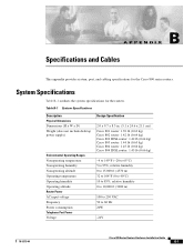
... B-1 outlines the system specifications for the Cisco 800 series routers. APPENDIX B Specifications and Cables This appendix provides system, port, and cabling specifications for the routers. Table B-1 System Specifications Description Physical Dimensions Dimensions (H x W x D) Weight (does not include desktop power supply) ... Design Specification 2.0 x 9.7 x 8.3 in. (5.1 x 24.6 x 21.1 cm) Cisco 801 router: 1.39 lb (0.63 kg) Cisco 802 router: 1.42 lb (0.64 kg) Cisco 802 IDSL router: 1.42 lb (0.64 kg) Cisco 803 router: 1.44 lb (0.65 kg) Cisco 804 router: 1.45 lb (0.66 kg) Cisco 804 IDSL...
... B-1 outlines the system specifications for the Cisco 800 series routers. APPENDIX B Specifications and Cables This appendix provides system, port, and cabling specifications for the routers. Table B-1 System Specifications Description Physical Dimensions Dimensions (H x W x D) Weight (does not include desktop power supply) ... Design Specification 2.0 x 9.7 x 8.3 in. (5.1 x 24.6 x 21.1 cm) Cisco 801 router: 1.39 lb (0.63 kg) Cisco 802 router: 1.42 lb (0.64 kg) Cisco 802 IDSL router: 1.42 lb (0.64 kg) Cisco 803 router: 1.44 lb (0.65 kg) Cisco 804 router: 1.45 lb (0.66 kg) Cisco 804 IDSL...
Hardware Installation Guide
Page 56
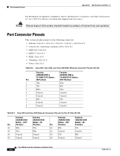
Port Connector Pinouts Appendix B Specifications and Cables For information on regulatory compliance, refer to all national laws and regulations. TX- 7 Unused Unused 8 Unused Unused Table B-3 Cisco 803 and Cisco 804 Ethernet Connector Pinouts for connecting a terminal or PC)-Table B-7 • ISDN S/T-Table B-8 • ...ISDN U-Table B-9 • IDSL-Table B-10 • Telephone-Table B-11 • Power-Table B-12 Table B-2 Cisco 801, Cisco 802, and Cisco 802 IDSL Ethernet Connector Pinouts (RJ-45) Function Function (HUB/NO HUB or (HUB/NO HUB or TO HUB/TO PC Button...
Port Connector Pinouts Appendix B Specifications and Cables For information on regulatory compliance, refer to all national laws and regulations. TX- 7 Unused Unused 8 Unused Unused Table B-3 Cisco 803 and Cisco 804 Ethernet Connector Pinouts for connecting a terminal or PC)-Table B-7 • ISDN S/T-Table B-8 • ...ISDN U-Table B-9 • IDSL-Table B-10 • Telephone-Table B-11 • Power-Table B-12 Table B-2 Cisco 801, Cisco 802, and Cisco 802 IDSL Ethernet Connector Pinouts (RJ-45) Function Function (HUB/NO HUB or (HUB/NO HUB or TO HUB/TO PC Button...
Hardware Installation Guide
Page 57
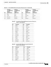
... B6 TX3- OUT Position) RX- Unused RX- C8 Unused D2 RX1- B8 Unused C2 RX3- C8 Unused D2 RX2- 78-5373-04 Cisco 800 Series Routers Hardware Installation Guide B-3 IN Position) TX- D4 Unused D6 TX1- C4 Unused C6 TX3- C4 Unused C6 TX2- D8 Unused ... RX2+ C3 TX2+ C5 Unused C7 Unused D1 RX1+ D3 TX1+ D5 Unused D7 Unused Pin Function B2 RX3- Appendix B Specifications and Cables Port Connector Pinouts Table B-4 Cisco 804 IDSL Ethernet Connector Pinouts for Port 1 Only (RJ-45) Function Function (TO HUB/TO PC (TO HUB/TO PC Button...
... B6 TX3- OUT Position) RX- Unused RX- C8 Unused D2 RX1- B8 Unused C2 RX3- C8 Unused D2 RX2- 78-5373-04 Cisco 800 Series Routers Hardware Installation Guide B-3 IN Position) TX- D4 Unused D6 TX1- C4 Unused C6 TX3- C4 Unused C6 TX2- D8 Unused ... RX2+ C3 TX2+ C5 Unused C7 Unused D1 RX1+ D3 TX1+ D5 Unused D7 Unused Pin Function B2 RX3- Appendix B Specifications and Cables Port Connector Pinouts Table B-4 Cisco 804 IDSL Ethernet Connector Pinouts for Port 1 Only (RJ-45) Function Function (TO HUB/TO PC (TO HUB/TO PC Button...
Hardware Installation Guide
Page 58
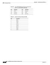
Port Connector Pinouts Appendix B Specifications and Cables Table B-6 Cisco 804 IDSL Ethernet Connector Pinouts for Ports 2, 3, and 4 (RJ-45) (continued) Pin Function D3 TX2+ D5 Unused D7 Unused Pin Function D4 Unused D6 TX2- D8 Unused Table B-7 Console Connector Pinouts (RJ-45) Pin Function 1 RTS 2 DTR 3 TXD 4 GND 5 GND 6 RXD 7 DSR 8 CTS Cisco 800 Series Routers Hardware Installation Guide B-4 78-5373-04
Port Connector Pinouts Appendix B Specifications and Cables Table B-6 Cisco 804 IDSL Ethernet Connector Pinouts for Ports 2, 3, and 4 (RJ-45) (continued) Pin Function D3 TX2+ D5 Unused D7 Unused Pin Function D4 Unused D6 TX2- D8 Unused Table B-7 Console Connector Pinouts (RJ-45) Pin Function 1 RTS 2 DTR 3 TXD 4 GND 5 GND 6 RXD 7 DSR 8 CTS Cisco 800 Series Routers Hardware Installation Guide B-4 78-5373-04
Hardware Installation Guide
Page 59
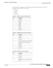
Appendix B Specifications and Cables Port Connector Pinouts 78-5373-04 The console port is configured as follows: • 9600 baud • 8 data bits • No parity • ... (Tip) 5 U interface network connection (Ring) 6 Unused 7 Unused 8 Unused Table B-10 IDSL Connector Pinouts (RJ-45) Pin Function 1 Unused 2 Unused 3 Unused 4 IDSL interface network connection (Tip) Cisco 800 Series Routers Hardware Installation Guide B-5 The default parameters for the console port are as a data communications equipment (DCE) device.
Appendix B Specifications and Cables Port Connector Pinouts 78-5373-04 The console port is configured as follows: • 9600 baud • 8 data bits • No parity • ... (Tip) 5 U interface network connection (Ring) 6 Unused 7 Unused 8 Unused Table B-10 IDSL Connector Pinouts (RJ-45) Pin Function 1 Unused 2 Unused 3 Unused 4 IDSL interface network connection (Tip) Cisco 800 Series Routers Hardware Installation Guide B-5 The default parameters for the console port are as a data communications equipment (DCE) device.
Hardware Installation Guide
Page 60
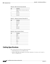
... Function 1 Unused 2 Unused 3 Ring 4 Tip 5 Unused 6 Unused Table B-12 Power Connector Pinouts Pin Function 1 ROF 2 RTN 3 Unused 4 Unused 5 +5 6 RTN 7 -71 8 -24 Cabling Specifications This section provides the following cabling specifications: • Straight-through and crossover Ethernet cables. • Ethernet, ISDN, IDSL and telephone cable distance limitations. (A telephone cable connects a device to a telephone...
... Function 1 Unused 2 Unused 3 Ring 4 Tip 5 Unused 6 Unused Table B-12 Power Connector Pinouts Pin Function 1 ROF 2 RTN 3 Unused 4 Unused 5 +5 6 RTN 7 -71 8 -24 Cabling Specifications This section provides the following cabling specifications: • Straight-through and crossover Ethernet cables. • Ethernet, ISDN, IDSL and telephone cable distance limitations. (A telephone cable connects a device to a telephone...
Hardware Installation Guide
Page 61
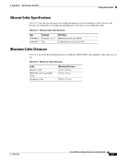
Table B-13 Ethernet Cable Specifications Type 10BASE-T 10BASE-T Category Category 3 or 5 N/A Shielding Shielded twisted-pair (STP) Unshielded twisted-pair (UTP) Maximum Cable Distances Table B-14 ... ft (10 m) 500 ft (152 m) 78-5373-04 Cisco 800 Series Routers Hardware Installation Guide B-7 Refer to the Glossary for straight-through Ethernet cable and crossover Ethernet cable. Appendix B Specifications and Cables Cabling Specifications Ethernet Cable Specifications Table B-13 lists the specifications for definitions of Ethernet, ISDN, IDSL, and telephone cables that ...
Table B-13 Ethernet Cable Specifications Type 10BASE-T 10BASE-T Category Category 3 or 5 N/A Shielding Shielded twisted-pair (STP) Unshielded twisted-pair (UTP) Maximum Cable Distances Table B-14 ... ft (10 m) 500 ft (152 m) 78-5373-04 Cisco 800 Series Routers Hardware Installation Guide B-7 Refer to the Glossary for straight-through Ethernet cable and crossover Ethernet cable. Appendix B Specifications and Cables Cabling Specifications Ethernet Cable Specifications Table B-13 lists the specifications for definitions of Ethernet, ISDN, IDSL, and telephone cables that ...
Hardware Installation Guide
Page 62
Cabling Specifications Appendix B Specifications and Cables Cisco 800 Series Routers Hardware Installation Guide B-8 78-5373-04
Cabling Specifications Appendix B Specifications and Cables Cisco 800 Series Routers Hardware Installation Guide B-8 78-5373-04
Hardware Installation Guide
Page 63
E 78-5373-04 Cisco 800 Series Routers Hardware Installation Guide GL-1 D DRAM Dynamic RAM that stores information in capacitors that wires a pin to TX+. GLOSSARY Numerics 10BASE-T The 10-Mbps baseband Ethernet specification that uses two pairs of twisted-pair cabling (Category 3 ...or 5): one data channel (D channel) for circuit-switched communication of voice, video, and data. This cable connects two similar devices, for receiving data. C Cisco 800 Fast Step Application...
E 78-5373-04 Cisco 800 Series Routers Hardware Installation Guide GL-1 D DRAM Dynamic RAM that stores information in capacitors that wires a pin to TX+. GLOSSARY Numerics 10BASE-T The 10-Mbps baseband Ethernet specification that uses two pairs of twisted-pair cabling (Category 3 ...or 5): one data channel (D channel) for circuit-switched communication of voice, video, and data. This cable connects two similar devices, for receiving data. C Cisco 800 Fast Step Application...
Hardware Installation Guide
Page 67
... panels, illustrated 1-4 to 1-7 B channels A-1 brackets, illustrated 2-19 BRI A-1 C cable lock, illustrated 1-4 to 1-7 cables and router damage 2-4 distances, maximum B-7 Ethernet, types 2-6 included with router 2-4 specifications B-6 caution statements, defined viii Cisco reseller, contacting 3-7 connecting analog telephone 2-15 digital telephone 2-14 Ethernet devices 2-6 fax 2-15 hubs 2-8 IDSL line 2-13 ISDN line 2-10 to 2-13 78...
... panels, illustrated 1-4 to 1-7 B channels A-1 brackets, illustrated 2-19 BRI A-1 C cable lock, illustrated 1-4 to 1-7 cables and router damage 2-4 distances, maximum B-7 Ethernet, types 2-6 included with router 2-4 specifications B-6 caution statements, defined viii Cisco reseller, contacting 3-7 connecting analog telephone 2-15 digital telephone 2-14 Ethernet devices 2-6 fax 2-15 hubs 2-8 IDSL line 2-13 ISDN line 2-10 to 2-13 78...
Hardware Installation Guide
Page 68
... illustrated 1-4 to 1-6 settings 2-6 to 2-7 hubs, connecting 2-8 humidity specifications B-1 I IDSL concepts A-1 IDSL LEDs, illustrated 1-4 IDSL line, connecting 2-13 IDSL port described 1-2 illustrated 1-6, 1-7 installation verifying 2-20 warnings 2-2 ISDN concepts A-1 ISDN line, connecting 2-10 to 2-13 ISDN S/T port described 1-2 illustrated 1-5 ISDN U port described 1-2 illustrated 1-5, 1-6 L LEDs IN-2 Cisco 800 Series Routers Hardware Installation Guide described 1-7 illustrated...
... illustrated 1-4 to 1-6 settings 2-6 to 2-7 hubs, connecting 2-8 humidity specifications B-1 I IDSL concepts A-1 IDSL LEDs, illustrated 1-4 IDSL line, connecting 2-13 IDSL port described 1-2 illustrated 1-6, 1-7 installation verifying 2-20 warnings 2-2 ISDN concepts A-1 ISDN line, connecting 2-10 to 2-13 ISDN S/T port described 1-2 illustrated 1-5 ISDN U port described 1-2 illustrated 1-5, 1-6 L LEDs IN-2 Cisco 800 Series Routers Hardware Installation Guide described 1-7 illustrated...

Hardware Installation Guide
Page 69
... connecting 2-14, 2-15 ports described 1-2 illustrated 1-5, 1-6 temperature specifications B-1 terminal, connecting 2-17 TO HUB/TO PC button illustrated 1-6 to 1-7 settings 2-6 to 2-20 warnings, installation 2-2 weight specifications B-1 workstation, connecting 2-9 U U interface A-1 United Kingdom master sockets 2-16 78-5373-04 Cisco 800 Series Routers Hardware Installation Guide IN-3 to 2-4 V voltage specifications B-1 W wall brackets, illustrated 2-19 wall mounting 2-19...
... connecting 2-14, 2-15 ports described 1-2 illustrated 1-5, 1-6 temperature specifications B-1 terminal, connecting 2-17 TO HUB/TO PC button illustrated 1-6 to 1-7 settings 2-6 to 2-20 warnings, installation 2-2 weight specifications B-1 workstation, connecting 2-9 U U interface A-1 United Kingdom master sockets 2-16 78-5373-04 Cisco 800 Series Routers Hardware Installation Guide IN-3 to 2-4 V voltage specifications B-1 W wall brackets, illustrated 2-19 wall mounting 2-19...