Hardware Installation Guide
Page 2
..., Berkeley (UCB) as part of UCB's public domain version of California. You can radiate radio-frequency energy and, if not installed and used in accordance with Cisco's installation instructions, it off. could void the FCC approval and negate your equipment is no longer complying with radio and television reception. The following measures: • Turn the television or radio antenna until the interference...
..., Berkeley (UCB) as part of UCB's public domain version of California. You can radiate radio-frequency energy and, if not installed and used in accordance with Cisco's installation instructions, it off. could void the FCC approval and negate your equipment is no longer complying with radio and television reception. The following measures: • Turn the television or radio antenna until the interference...
Hardware Installation Guide
Page 7
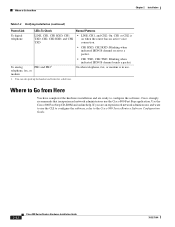
... the network as quickly as installing, mounting, and verifying the connections to your router. • ISDN and IDSL Concepts-Describes how ISDN is intended for installation as well as possible. Conventions This section describes the conventions used in this guide. The goal of all levels of router LEDs, ports, and other components. • Installation-Provides information on the router. • Specifications and Cables-Provides router, port, and cable specifications...
... the network as quickly as installing, mounting, and verifying the connections to your router. • ISDN and IDSL Concepts-Describes how ISDN is intended for installation as well as possible. Conventions This section describes the conventions used in this guide. The goal of all levels of router LEDs, ports, and other components. • Installation-Provides information on the router. • Specifications and Cables-Provides router, port, and cable specifications...
Hardware Installation Guide
Page 11
... with PGP versions 2.x through 8.x. PSIRT can access the CPI tool from the Alphabetical Index drop-down list, or click the Cisco Product Identification Tool link under Documentation & Tools. The correct public key to use a revoked or an expired encryption key. The Cisco Technical Support Website on your product with Cisco products and technologies. or for service. Cisco Technical Support Website The Cisco Technical Support Website provides online documents and tools for troubleshooting and...
... with PGP versions 2.x through 8.x. PSIRT can access the CPI tool from the Alphabetical Index drop-down list, or click the Cisco Product Identification Tool link under Documentation & Tools. The correct public key to use a revoked or an expired encryption key. The Cisco Technical Support Website on your product with Cisco products and technologies. or for service. Cisco Technical Support Website The Cisco Technical Support Website provides online documents and tools for troubleshooting and...
Hardware Installation Guide
Page 16
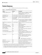
...) Ethernet networks. Provides a Windows 95-, Windows 98-, and Windows NT-based software tool for the 8-MB Flash memory upgrade kit is a service port. Cable lock All Provides a way to IDSL network. Cisco 800 Series Routers Hardware Installation Guide 1-2 78-5373-04 Provides connection to physically secure the router. Supports Cisco IOS software. Note The console port is MEM800-8F and the numbers for troubleshooting. You cannot connect S/T devices to ISDN U network. Table 1-1 Cisco 800 Series Feature Summary Feature 10BASE-T Ethernet port(s) ISDN...
...) Ethernet networks. Provides a Windows 95-, Windows 98-, and Windows NT-based software tool for the 8-MB Flash memory upgrade kit is a service port. Cable lock All Provides a way to IDSL network. Cisco 800 Series Routers Hardware Installation Guide 1-2 78-5373-04 Provides connection to physically secure the router. Supports Cisco IOS software. Note The console port is MEM800-8F and the numbers for troubleshooting. You cannot connect S/T devices to ISDN U network. Table 1-1 Cisco 800 Series Feature Summary Feature 10BASE-T Ethernet port(s) ISDN...

Hardware Installation Guide
Page 18
... an overlaid cross ( ) appears above a port, you must not connect the port to a public network that follows the European Union standards. Ethernet port Connect Ethernet network device. Power switch l = On. = Standby or no power output. 11666 LINK HUB NO HUB ETHERNET 10 BASE T Cisco 801 CONSOLE ISDN S/T Cable lock Use cable lock to external NT1 or ISDN wall jack. Cisco 800 Series Routers Hardware Installation Guide 1-4 78-5373-04 Connecting the port to this section show the...
... an overlaid cross ( ) appears above a port, you must not connect the port to a public network that follows the European Union standards. Ethernet port Connect Ethernet network device. Power switch l = On. = Standby or no power output. 11666 LINK HUB NO HUB ETHERNET 10 BASE T Cisco 801 CONSOLE ISDN S/T Cable lock Use cable lock to external NT1 or ISDN wall jack. Cisco 800 Series Routers Hardware Installation Guide 1-4 78-5373-04 Connecting the port to this section show the...

Hardware Installation Guide
Page 19
...1-5 Cisco 802 Router Back Panel Link LED Indicates state of Ethernet port. Console port Connect PC or terminal. PHONE 1 2 Locking power connector Connect power supply. 78-5373-04 Cisco 800 Series Routers Hardware Installation Guide 1-5 HUB/NO HUB button (for Ethernet port) Determines cable type for Ethernet device connection. ISDN BRI S/T port Connect to ISDN wall jack. ISDN BRI U port Connect to external NT1 or ISDN wall jack. Power switch l = On. = Standby or no power output. 11668 Cable lock Use cable lock to physically secure router. Console port Connect...
...1-5 Cisco 802 Router Back Panel Link LED Indicates state of Ethernet port. Console port Connect PC or terminal. PHONE 1 2 Locking power connector Connect power supply. 78-5373-04 Cisco 800 Series Routers Hardware Installation Guide 1-5 HUB/NO HUB button (for Ethernet port) Determines cable type for Ethernet device connection. ISDN BRI S/T port Connect to ISDN wall jack. ISDN BRI U port Connect to external NT1 or ISDN wall jack. Power switch l = On. = Standby or no power output. 11668 Cable lock Use cable lock to physically secure router. Console port Connect...

Hardware Installation Guide
Page 20
...cable type for Ethernet device connection. IDSL port Connect to ISDN wall jack. PHONE 1 2 Locking power connector Connect power supply. Console port Connect PC or terminal. ISDN BRI U port Connect to IDSL wall jack. Locking power connector Connect power supply. 30771 Cisco 800 Series Routers Hardware Installation Guide 1-6 78-5373-04 LINK TO TO HUB PC ETHERNET 10 BASE T CONSOLE Cisco 802 IDSL IDSL Cable lock Use cable lock to physically secure router. Back Panels Chapter 1 Overview Figure 1-7 Cisco 804 Router Back Panel Ethernet ports Connect Ethernet network...
...cable type for Ethernet device connection. IDSL port Connect to ISDN wall jack. PHONE 1 2 Locking power connector Connect power supply. Console port Connect PC or terminal. ISDN BRI U port Connect to IDSL wall jack. Locking power connector Connect power supply. 30771 Cisco 800 Series Routers Hardware Installation Guide 1-6 78-5373-04 LINK TO TO HUB PC ETHERNET 10 BASE T CONSOLE Cisco 802 IDSL IDSL Cable lock Use cable lock to physically secure router. Back Panels Chapter 1 Overview Figure 1-7 Cisco 804 Router Back Panel Ethernet ports Connect Ethernet network...

Hardware Installation Guide
Page 21
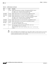
... Router Back Panel Ethernet ports Connect Ethernet network devices. IDSL port Connect to physically secure router. TO TO HUB PC ETHERNET 10 BASE T 1 2 3 4 TO HUB/TO PC (for Ethernet port 1) Determines cable type for Cisco 801 and 803 routers. Power switch l = On. = Standby or no power output. 30772 Cable lock Use cable lock to IDSL wall jack. Table 1-3 LED Functions LED Color OK Green NT1 Green LINE LAN LAN RXD LAN TXD LKØ, LK1, LK2, LK3 Green Green Green Green Green ETHERNET Green 1, 2, 3, 4 Function On when power is supplied...
... Router Back Panel Ethernet ports Connect Ethernet network devices. IDSL port Connect to physically secure router. TO TO HUB PC ETHERNET 10 BASE T 1 2 3 4 TO HUB/TO PC (for Ethernet port 1) Determines cable type for Cisco 801 and 803 routers. Power switch l = On. = Standby or no power output. 30772 Cable lock Use cable lock to IDSL wall jack. Table 1-3 LED Functions LED Color OK Green NT1 Green LINE LAN LAN RXD LAN TXD LKØ, LK1, LK2, LK3 Green Green Green Green Green ETHERNET Green 1, 2, 3, 4 Function On when power is supplied...
Hardware Installation Guide
Page 22
... data connection and the line speed is 64 kbps. CH1 and CH2 are sent from the second ISDN B channel. Cisco 803 and 804 routers only. Blinks when the connection has a problem. Cisco 800 Series Routers Hardware Installation Guide 1-8 78-5373-04 On when basic telephone service is connected. For IDSL routers, see the Note following this table. On when Ethernet device is in use. On when a call is connected on...
... data connection and the line speed is 64 kbps. CH1 and CH2 are sent from the second ISDN B channel. Cisco 803 and 804 routers only. Blinks when the connection has a problem. Cisco 800 Series Routers Hardware Installation Guide 1-8 78-5373-04 On when basic telephone service is connected. For IDSL routers, see the Note following this table. On when Ethernet device is in use. On when a call is connected on...
Hardware Installation Guide
Page 24
... heat up when connected to power and ground and can cause severe injury or damage your router European Union Statements The following warnings: Warning Only trained and qualified personnel should be allowed to all national laws and regulations. Cisco 800 Series Routers Hardware Installation Guide 2-2 78-5373-04 Use caution when connecting cables. Warning Ultimate disposal of public network can cause serious...
... heat up when connected to power and ground and can cause severe injury or damage your router European Union Statements The following warnings: Warning Only trained and qualified personnel should be allowed to all national laws and regulations. Cisco 800 Series Routers Hardware Installation Guide 2-2 78-5373-04 Use caution when connecting cables. Warning Ultimate disposal of public network can cause serious...

Hardware Installation Guide
Page 26
... "Cabling Specifications" section in . Connecting the port to this appendix does not provide specifications for use with red ISDN U cable • Product documentation Preinstallation Activities Before you have a Cisco 801 or Cisco 803 router, do the following: Cisco 800 Series Routers Hardware Installation Guide 2-4 78-5373-04 Table 2-1 Router Box Contents • Power cord (black) • Desktop power supply • Console cable (light blue) • DB-9-to-RJ-45 adapter for use with light blue console cable...
... "Cabling Specifications" section in . Connecting the port to this appendix does not provide specifications for use with red ISDN U cable • Product documentation Preinstallation Activities Before you have a Cisco 801 or Cisco 803 router, do the following: Cisco 800 Series Routers Hardware Installation Guide 2-4 78-5373-04 Table 2-1 Router Box Contents • Power cord (black) • Desktop power supply • Console cable (light blue) • DB-9-to-RJ-45 adapter for use with light blue console cable...
Hardware Installation Guide
Page 27
..., you need to mount your router. 8. Chapter 2 Installation Installing Your Router Step 3 Step 4 Step 5 Step 6 Step 7 Step 8 Step 9 • If you are in North America, ask your telephone service provider for troubleshooting). 6. For more information, see the "Maximum Cable Distances" section in Appendix B, "Specifications and Cables." If you have a Cisco 801 or Cisco 803 router and plan to connect a digital telephone, you need to the power source...
..., you need to mount your router. 8. Chapter 2 Installation Installing Your Router Step 3 Step 4 Step 5 Step 6 Step 7 Step 8 Step 9 • If you are in North America, ask your telephone service provider for troubleshooting). 6. For more information, see the "Maximum Cable Distances" section in Appendix B, "Specifications and Cables." If you have a Cisco 801 or Cisco 803 router and plan to connect a digital telephone, you need to the power source...
Hardware Installation Guide
Page 44
... B channel sends a packet. Where to the Cisco 800 Series Routers Software Configuration Guide. 2-22 Cisco 800 Series Routers Hardware Installation Guide 78-5373-04 On when telephone, fax, or modem is on when the router has an active voice connection. • CH1 RXD, CH2 RXD: Blinking when indicated ISDN B channel receives a packet. Use the Cisco 800 Fast Step CD-ROM and online help. If you are ready to configure the software.
... B channel sends a packet. Where to the Cisco 800 Series Routers Software Configuration Guide. 2-22 Cisco 800 Series Routers Hardware Installation Guide 78-5373-04 On when telephone, fax, or modem is on when the router has an active voice connection. • CH1 RXD, CH2 RXD: Blinking when indicated ISDN B channel receives a packet. Use the Cisco 800 Fast Step CD-ROM and online help. If you are ready to configure the software.

Hardware Installation Guide
Page 47
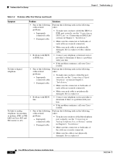
... make sure you have cabled the devices correctly, see Table 2-2 in Chapter 2, "Installation." • Improperly functioning network interface card (NIC) on server, PC, or workstation. • Run the NIC diagnostic supplied by the vendor to Cisco 801 and Cisco 803 Routers" section in Chapter 2, "Installation." • Make sure the connectors at both ends of the cable are using the right type of North America, contact your telephone service...
... make sure you have cabled the devices correctly, see Table 2-2 in Chapter 2, "Installation." • Improperly functioning network interface card (NIC) on server, PC, or workstation. • Run the NIC diagnostic supplied by the vendor to Cisco 801 and Cisco 803 Routers" section in Chapter 2, "Installation." • Make sure the connectors at both ends of the cable are using the right type of North America, contact your telephone service...
Hardware Installation Guide
Page 48
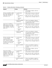
... "Connecting a Digital connected cable. Damaged cable. If it is, replace it is a problem with ISDN line. • Contact your Cisco reseller. No link to determine if there is not physically damaged. in Chapter 2, "Installation." • Make sure the connectors at both ends of the following Perform the following cable-related order: problems: • To make sure you have cabled the ISDN or - Cisco 800 Series Routers Hardware Installation Guide...
... "Connecting a Digital connected cable. Damaged cable. If it is, replace it is a problem with ISDN line. • Contact your Cisco reseller. No link to determine if there is not physically damaged. in Chapter 2, "Installation." • Make sure the connectors at both ends of the following Perform the following cable-related order: problems: • To make sure you have cabled the ISDN or - Cisco 800 Series Routers Hardware Installation Guide...
Hardware Installation Guide
Page 50
... RXD, or CH2 TXD are securely connected. • Make sure each cable are off.) • A cable-related problem: - determine if there is not physically damaged. Cisco 800 Series Routers Hardware Installation Guide 3-6 78-5373-04 Damaged cable. • Problem with your line. • If the problem continues, call your telephone or Internet or IDSL line. If one is damaged, replace it . • Problem with ISDN • Contact...
... RXD, or CH2 TXD are securely connected. • Make sure each cable are off.) • A cable-related problem: - determine if there is not physically damaged. Cisco 800 Series Routers Hardware Installation Guide 3-6 78-5373-04 Damaged cable. • Problem with your line. • If the problem continues, call your telephone or Internet or IDSL line. If one is damaged, replace it . • Problem with ISDN • Contact...
Hardware Installation Guide
Page 59
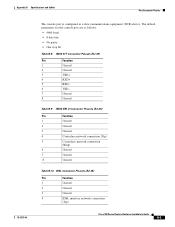
... 1 Unused 2 Unused 3 TXD+ 4 RXD+ 5 RXD- 6 TXD- 7 Unused 8 Unused Table B-9 ISDN BRI U Connector Pinouts (RJ-45) Pin Function 1 Unused 2 Unused 3 Unused 4 U interface network connection (Tip) 5 U interface network connection (Ring) 6 Unused 7 Unused 8 Unused Table B-10 IDSL Connector Pinouts (RJ-45) Pin Function 1 Unused 2 Unused 3 Unused 4 IDSL interface network connection (Tip) Cisco 800 Series Routers Hardware Installation Guide B-5 The default parameters for the console port are as a data communications equipment (DCE...
... 1 Unused 2 Unused 3 TXD+ 4 RXD+ 5 RXD- 6 TXD- 7 Unused 8 Unused Table B-9 ISDN BRI U Connector Pinouts (RJ-45) Pin Function 1 Unused 2 Unused 3 Unused 4 U interface network connection (Tip) 5 U interface network connection (Ring) 6 Unused 7 Unused 8 Unused Table B-10 IDSL Connector Pinouts (RJ-45) Pin Function 1 Unused 2 Unused 3 Unused 4 IDSL interface network connection (Tip) Cisco 800 Series Routers Hardware Installation Guide B-5 The default parameters for the console port are as a data communications equipment (DCE...
Hardware Installation Guide
Page 63
... two data communications equipment (DCE) devices. E 78-5373-04 Cisco 800 Series Routers Hardware Installation Guide GL-1 GLOSSARY Numerics 10BASE-T The 10-Mbps baseband Ethernet specification that wires a pin to TX+. crossover Ethernet cable A cable that uses two pairs of the router software configuration. It also monitors the status of voice, video, and data. This cable connects two similar devices, for circuit-switched communication of the ISDN interface, error detail, and usage statistics.
... two data communications equipment (DCE) devices. E 78-5373-04 Cisco 800 Series Routers Hardware Installation Guide GL-1 GLOSSARY Numerics 10BASE-T The 10-Mbps baseband Ethernet specification that wires a pin to TX+. crossover Ethernet cable A cable that uses two pairs of the router software configuration. It also monitors the status of voice, video, and data. This cable connects two similar devices, for circuit-switched communication of the ISDN interface, error detail, and usage statistics.
Hardware Installation Guide
Page 68
... to 2-13 ISDN S/T port described 1-2 illustrated 1-5 ISDN U port described 1-2 illustrated 1-5, 1-6 L LEDs IN-2 Cisco 800 Series Routers Hardware Installation Guide described 1-7 illustrated 1-3 to 1-6 locking power connector, illustrated 1-4 to 1-7 M modem, connecting 2-15 mounting the router 2-18 N network device button settings 2-6 to 2-7 NT1 feature 1-2 P panels, illustrated 1-4 to 1-7 PC, connecting 2-9, 2-17 port connector pinouts B-2 to B-6 ports for specific routers 1-3 power problems 3-2 specifications B-1 verifying 2-20 power supply connecting 2-18 power switch illustrated 1-4 to...
... to 2-13 ISDN S/T port described 1-2 illustrated 1-5 ISDN U port described 1-2 illustrated 1-5, 1-6 L LEDs IN-2 Cisco 800 Series Routers Hardware Installation Guide described 1-7 illustrated 1-3 to 1-6 locking power connector, illustrated 1-4 to 1-7 M modem, connecting 2-15 mounting the router 2-18 N network device button settings 2-6 to 2-7 NT1 feature 1-2 P panels, illustrated 1-4 to 1-7 PC, connecting 2-9, 2-17 port connector pinouts B-2 to B-6 ports for specific routers 1-3 power problems 3-2 specifications B-1 verifying 2-20 power supply connecting 2-18 power switch illustrated 1-4 to...

Hardware Installation Guide
Page 69
... 2-7 specifications cabling B-6 system B-1 startup problems 3-2 T table mounting 2-18 telephone connecting 2-14, 2-15 ports described 1-2 illustrated 1-5, 1-6 temperature specifications B-1 terminal, connecting 2-17 TO HUB/TO PC button illustrated 1-6 to 1-7 settings 2-6 to 2-20 warnings, installation 2-2 weight specifications B-1 workstation, connecting 2-9 U U interface A-1 United Kingdom master sockets 2-16 78-5373-04 Cisco 800 Series Routers Hardware Installation Guide IN-3 to 2-4 V voltage specifications B-1 W wall brackets, illustrated 2-19 wall mounting 2-19 to 2-7 troubleshooting...
... 2-7 specifications cabling B-6 system B-1 startup problems 3-2 T table mounting 2-18 telephone connecting 2-14, 2-15 ports described 1-2 illustrated 1-5, 1-6 temperature specifications B-1 terminal, connecting 2-17 TO HUB/TO PC button illustrated 1-6 to 1-7 settings 2-6 to 2-20 warnings, installation 2-2 weight specifications B-1 workstation, connecting 2-9 U U interface A-1 United Kingdom master sockets 2-16 78-5373-04 Cisco 800 Series Routers Hardware Installation Guide IN-3 to 2-4 V voltage specifications B-1 W wall brackets, illustrated 2-19 wall mounting 2-19 to 2-7 troubleshooting...


