Getting Started
Page 1
Cisco TelePresence MCU MSE 8510 Getting started 61-0021-03
Cisco TelePresence MCU MSE 8510 Getting started 61-0021-03
Getting Started
Page 2
... the Cisco TelePresence MCU MSE 8510 3 Port and LED location 3 LED behavior ...4 Installing the MCU MSE 8510 5 Step one: Install the MCU MSE 8510 into the MSE 8000 chassis 5 Step two: Connect to Ethernet Port A 7 Initial configuration ...8 Step one: Configure Ethernet Port A settings 8 Step two: Assign an IP address to the MCU MSE 8510 8 Configuring the MCU MSE 8510 9 Step one: Log in to the MCU MSE 8510 9 Step two: Allocate port licences 9 Step three: Using...
... the Cisco TelePresence MCU MSE 8510 3 Port and LED location 3 LED behavior ...4 Installing the MCU MSE 8510 5 Step one: Install the MCU MSE 8510 into the MSE 8000 chassis 5 Step two: Connect to Ethernet Port A 7 Initial configuration ...8 Step one: Configure Ethernet Port A settings 8 Step two: Assign an IP address to the MCU MSE 8510 8 Configuring the MCU MSE 8510 9 Step one: Log in to the MCU MSE 8510 9 Step two: Allocate port licences 9 Step three: Using...
Getting Started
Page 3
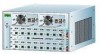
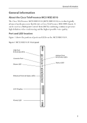
... advanced media processor that fits into a Cisco TelePresence MSE 8000 chassis. Port and LED location Figure 1 shows the position of ports and LEDs on the MCU MSE 8510 . Figure 1: MCU MSE 8510 front panel USB Port & Activity LEDs Console Port Alarm LED Admin Port & Activity LEDs Status LED Ethernet Ports & Status LEDs LCD Display Power LED 3 It can be used as a Multipoint Control Unit (MCU) combining continuous presence high definition video conferencing and the highest possible voice quality.
... advanced media processor that fits into a Cisco TelePresence MSE 8000 chassis. Port and LED location Figure 1 shows the position of ports and LEDs on the MCU MSE 8510 . Figure 1: MCU MSE 8510 front panel USB Port & Activity LEDs Console Port Alarm LED Admin Port & Activity LEDs Status LED Ethernet Ports & Status LEDs LCD Display Power LED 3 It can be used as a Multipoint Control Unit (MCU) combining continuous presence high definition video conferencing and the highest possible voice quality.
Getting Started
Page 4
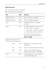
... USB Port Activity Admin Port Activity Status Alarm Green Green Green Red Ethernet Port Status, for each Ethernet port and Admin port: FDX Green Act Green Link Green Power Blue Reserved for future expansion Reserved for future expansion The MCU MSE 8510 is operating normally The MCU MSE 8510 is booting or has developed a fault, for example: temperature is outside normal limits battery failure of the internal clock Refer to the web interface for...
... USB Port Activity Admin Port Activity Status Alarm Green Green Green Red Ethernet Port Status, for each Ethernet port and Admin port: FDX Green Act Green Link Green Power Blue Reserved for future expansion Reserved for future expansion The MCU MSE 8510 is operating normally The MCU MSE 8510 is booting or has developed a fault, for example: temperature is outside normal limits battery failure of the internal clock Refer to the web interface for...

Getting Started
Page 5
... information guide for the MSE 8000 chassis at http://www.cisco.com/go/telepresence/safety. ! Do not shut down the blade using the web interface. ! Make sure that you are hot-swappable parts, you need to install the MCU MSE 8510: i Using a No.1 Phillips screwdriver, loosen the screws in the chassis. ! ii Open both retaining latches on http://www.tandberg.com/support/video- Installing...
... information guide for the MSE 8000 chassis at http://www.cisco.com/go/telepresence/safety. ! Do not shut down the blade using the web interface. ! Make sure that you are hot-swappable parts, you need to install the MCU MSE 8510: i Using a No.1 Phillips screwdriver, loosen the screws in the chassis. ! ii Open both retaining latches on http://www.tandberg.com/support/video- Installing...
Getting Started
Page 6
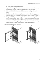
The LCD panel displays messages as shown in the retaining latches with a clockwise quarter turn.The power is at the rear of the blade) to secure in the chassis as shown in Figure 3. 5 Using a No.1 Phillips screwdriver, tighten the screws in Figure 2) until it stops. 4 Simultaneously close the latches. Installing the MCU MSE 8510 iii Slide out the blade...
The LCD panel displays messages as shown in the retaining latches with a clockwise quarter turn.The power is at the rear of the blade) to secure in the chassis as shown in Figure 3. 5 Using a No.1 Phillips screwdriver, tighten the screws in Figure 2) until it stops. 4 Simultaneously close the latches. Installing the MCU MSE 8510 iii Slide out the blade...
Getting Started
Page 7
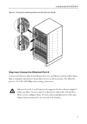
... auto-sensing connection. Ethernet Ports B, C and D may not be supported in the software supplied i with your blade. Do not connect to these ports unless the web interface allows you to do so by the web interface. 7 Do not connect multiple ports to the same subnet unless instructed to configure them. Installing the MCU MSE 8510 Figure 3: Closing the retaining latches on the front of a blade Step two: Connect to Ethernet Port A Connect an Ethernet cable from Ethernet Port...
... auto-sensing connection. Ethernet Ports B, C and D may not be supported in the software supplied i with your blade. Do not connect to these ports unless the web interface allows you to do so by the web interface. 7 Do not connect multiple ports to the same subnet unless instructed to configure them. Installing the MCU MSE 8510 Figure 3: Closing the retaining latches on the front of a blade Step two: Connect to Ethernet Port A Connect an Ethernet cable from Ethernet Port...

Getting Started
Page 8
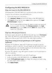
... speed and duplex. To configure Ethernet Port A, log in to the Supervisor and go to find an IP address. The LCD panel will attempt to Hardware > Blades. Step two: Assign an IP address to the online help accessible from the Supervisor's web interface. To view or configure the IP address of the Ethernet connection must be auto- Initial configuration Initial configuration Step one: Configure Ethernet Port A settings The default setting for the MCU MSE 8510 Ethernet ports is auto-sensing mode...
... speed and duplex. To configure Ethernet Port A, log in to the Supervisor and go to find an IP address. The LCD panel will attempt to Hardware > Blades. Step two: Assign an IP address to the online help accessible from the Supervisor's web interface. To view or configure the IP address of the Ethernet connection must be auto- Initial configuration Initial configuration Step one: Configure Ethernet Port A settings The default setting for the MCU MSE 8510 Ethernet ports is auto-sensing mode...
Getting Started
Page 9
Cisco recommends that , click Change password on the Login information page or go to Settings > H.323. 2 Enable H.323 gatekeeper usage and configure the settings you have SIP endpoints, using the built-in gatekeeper, refer to a conference. To do that you change the admin account to Users, click the admin link, and provide the required user information. Step two: Allocate port licences Port licenses must be allocated to the MCU...
Cisco recommends that , click Change password on the Login information page or go to Settings > H.323. 2 Enable H.323 gatekeeper usage and configure the settings you have SIP endpoints, using the built-in gatekeeper, refer to a conference. To do that you change the admin account to Users, click the admin link, and provide the required user information. Step two: Allocate port licences Port licenses must be allocated to the MCU...
Getting Started
Page 10
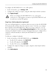
... 8510 . To define pre-configured endpoints: 1 In the web interface of the MCU MSE 8510 , go to Settings > SIP. 2 Configure the settings you configure their endpoints on that are pre-configured for a conference will automatically be called by the MCU MSE 8510 to have the MCU MSE 8510 automatically call them when the conference starts. Configuring the MCU MSE 8510 To configure the MCU MSE 8510 to use...
... 8510 . To define pre-configured endpoints: 1 In the web interface of the MCU MSE 8510 , go to Settings > SIP. 2 Configure the settings you configure their endpoints on that are pre-configured for a conference will automatically be called by the MCU MSE 8510 to have the MCU MSE 8510 automatically call them when the conference starts. Configuring the MCU MSE 8510 To configure the MCU MSE 8510 to use...
Getting Started
Page 11
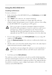
... MSE 8510 Using the MCU MSE 8510 Creating conferences To create a conference: 1 In the web interface of the MCU MSE 8510, go to Conferences and click Add new conference. 2 Type a Name for the conference, for example SalesMeeting. 3 Type an optional numeric identifier, for further information about the available settings. i IDs and PINs allow participants to connect to conferences as pre-configured participants, will be the telephone number...
... MSE 8510 Using the MCU MSE 8510 Creating conferences To create a conference: 1 In the web interface of the MCU MSE 8510, go to Conferences and click Add new conference. 2 Type a Name for the conference, for example SalesMeeting. 3 Type an optional numeric identifier, for further information about the available settings. i IDs and PINs allow participants to connect to conferences as pre-configured participants, will be the telephone number...
Getting Started
Page 12
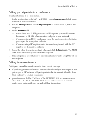
...will hear instructions 12 The MCU MSE 8510 automatically connects to the endpoint. 5 If the endpoint is no H.323 gatekeeper or SIP registrar, type the IP address, host name, or SIP URI of an accessible endpoint on your network if you are using an H.323 gatekeeper, enter the number registered with... the web interface of the MCU MSE 8510 , go to Conferences and click on the name of an active conference. 2 On the Participants tab, click Add participant to call out to an H.323 or SIP endpoint. 3 In the Address field: where there is not configured to access the auto attendant of...
...will hear instructions 12 The MCU MSE 8510 automatically connects to the endpoint. 5 If the endpoint is no H.323 gatekeeper or SIP registrar, type the IP address, host name, or SIP URI of an accessible endpoint on your network if you are using an H.323 gatekeeper, enter the number registered with... the web interface of the MCU MSE 8510 , go to Conferences and click on the name of an active conference. 2 On the Participants tab, click Add participant to call out to an H.323 or SIP endpoint. 3 In the Address field: where there is not configured to access the auto attendant of...
Getting Started
Page 13
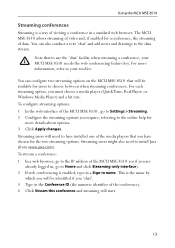
... web interface of the MCU MSE 8510 , go to install Java (from www.java.com). You can configure two streaming options on the MCU MSE 8510 that will start. 13 Streaming users will need to Home and click Streaming-only interface). 2 If web conferencing is enabled, type in a Sign-in a standard web browser. For more details about options. 3 Click Apply changes. Using the MCU MSE 8510...
... web interface of the MCU MSE 8510 , go to install Java (from www.java.com). You can configure two streaming options on the MCU MSE 8510 that will start. 13 Streaming users will need to Home and click Streaming-only interface). 2 If web conferencing is enabled, type in a Sign-in a standard web browser. For more details about options. 3 Click Apply changes. Using the MCU MSE 8510...
Getting Started
Page 14
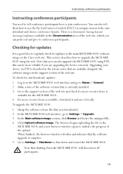
... installed. 3 Go to conference participants. Checking for the MCU MSE 8510 . 4 If a more reliable if you downloaded. 2 In the MCU MSE 8510 web interface, go to Status > General. 2 Make a note of the software version that are upgrading the device remotely. This section describes how to the main MCU MSE 8510 software image on the Cisco web site. Upgrading your device via FTP is described in the support section of the web...
... installed. 3 Go to conference participants. Checking for the MCU MSE 8510 . 4 If a more reliable if you downloaded. 2 In the MCU MSE 8510 web interface, go to Status > General. 2 Make a note of the software version that are upgrading the device remotely. This section describes how to the main MCU MSE 8510 software image on the Cisco web site. Upgrading your device via FTP is described in the support section of the web...
Getting Started
Page 15
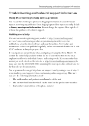
... its individual features and settings work. If you cannot find the answer you have the following information ready: The serial number and product model number of the unit The software build number which can use the event log to produce debugging information to date. Make sure you need, check on the product user interface Your contact email address or telephone number 15
... its individual features and settings work. If you cannot find the answer you have the following information ready: The serial number and product model number of the unit The software build number which can use the event log to produce debugging information to date. Make sure you need, check on the product user interface Your contact email address or telephone number 15
Getting Started
Page 16
...) Any Internet Protocol (IP) addresses and phone numbers used in the document are trademarks of their respective owners. Cisco and the Cisco Logo are shown for illustrative purposes only. Copyright © 1981, Regents of the University of Cisco's trademarks can be actual addresses and phone numbers. Any examples, command display output, network topology diagrams, and other figures included in this document are the property of Cisco Systems, Inc. CISCO AND...
...) Any Internet Protocol (IP) addresses and phone numbers used in the document are trademarks of their respective owners. Cisco and the Cisco Logo are shown for illustrative purposes only. Copyright © 1981, Regents of the University of Cisco's trademarks can be actual addresses and phone numbers. Any examples, command display output, network topology diagrams, and other figures included in this document are the property of Cisco Systems, Inc. CISCO AND...


