
User Guide
Page 1
At A Glance Cisco ATA 186 and Cisco ATA 188 Analog Telephone Adaptor 1 Overview 2 Installation 3 Configuration
At A Glance Cisco ATA 186 and Cisco ATA 188 Analog Telephone Adaptor 1 Overview 2 Installation 3 Configuration
User Guide
Page 2
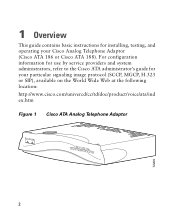
For configuration information for use by service providers and system administrators, refer to the Cisco ATA administrator's guide for installing, testing, and operating your particular signaling image protocol (SCCP, MGCP, H.323 or SIP), available on the World Wide Web at the following location: http://www.cisco.com/univercd/cc/td/doc/product/voice/ata/ind ex.htm Figure 1 Cisco ATA Analog Telephone Adaptor ANALOCGISTCELOEPAHTONAE1A8D6APTOR 2 72209 1 Overview This guide contains basic instructions for your Cisco Analog Telephone Adaptor (Cisco ATA 186 or Cisco ATA 188).
For configuration information for use by service providers and system administrators, refer to the Cisco ATA administrator's guide for installing, testing, and operating your particular signaling image protocol (SCCP, MGCP, H.323 or SIP), available on the World Wide Web at the following location: http://www.cisco.com/univercd/cc/td/doc/product/voice/ata/ind ex.htm Figure 1 Cisco ATA Analog Telephone Adaptor ANALOCGISTCELOEPAHTONAE1A8D6APTOR 2 72209 1 Overview This guide contains basic instructions for your Cisco Analog Telephone Adaptor (Cisco ATA 186 or Cisco ATA 188).

User Guide
Page 3
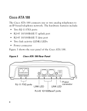
The hardware features include: • Function button • Two RJ-11 FXS ports • RJ-45 10BASE-T uplink port • Network activity (ACT) LED • Power connector Figure 2 shows the rear panel of the Cisco ATA 186. Figure 2 Cisco ATA 186 Rear Panel 72210 PHONE 1 PHONE 2 10BaseT ACT 5V RJ-11 FXS ports RJ-45 10BaseT Power connector ACT LED 3 Cisco ATA 186 The Cisco ATA 186 connects one or two analog telephones to an IP-based telephony network.
The hardware features include: • Function button • Two RJ-11 FXS ports • RJ-45 10BASE-T uplink port • Network activity (ACT) LED • Power connector Figure 2 shows the rear panel of the Cisco ATA 186. Figure 2 Cisco ATA 186 Rear Panel 72210 PHONE 1 PHONE 2 10BaseT ACT 5V RJ-11 FXS ports RJ-45 10BaseT Power connector ACT LED 3 Cisco ATA 186 The Cisco ATA 186 connects one or two analog telephones to an IP-based telephony network.
User Guide
Page 4
Cisco ATA 188 The Cisco ATA 188 connects one or two analog telephones to an IP-based telephony network. The hardware features include: • Two RJ-11 FXS ports • RJ-45 10/100BASE-T uplink port • RJ-45 10/100BASE-T data port • Two link activity (LINK) LEDs • Power connector Figure 3 shows the rear panel of the Cisco ATA 188. Figure 3 Cisco ATA 188 Rear Panel 72211 PHONE 1 PHONE 2 LINK 10/100 PC 10/100 UPLINK LINK 5V RJ-11 FXS ports LINK LED Power connector LINK LED RJ-45 10/100BaseT ports 4
Cisco ATA 188 The Cisco ATA 188 connects one or two analog telephones to an IP-based telephony network. The hardware features include: • Two RJ-11 FXS ports • RJ-45 10/100BASE-T uplink port • RJ-45 10/100BASE-T data port • Two link activity (LINK) LEDs • Power connector Figure 3 shows the rear panel of the Cisco ATA 188. Figure 3 Cisco ATA 188 Rear Panel 72211 PHONE 1 PHONE 2 LINK 10/100 PC 10/100 UPLINK LINK 5V RJ-11 FXS ports LINK LED Power connector LINK LED RJ-45 10/100BaseT ports 4

User Guide
Page 5
U verkeert in the translated safety warnings that could cause bodily injury. You are in a situation that accompanied this device. • Do not perform any equipment, be aware of each warning to people or makes the equipment unsafe. Use the statement number provided at the end of the hazards involved with electrical circuitry and be familiar with standard practices for preventing accidents. Warning IMPORTANT SAFETY INSTRUCTIONS This warning symbol means danger. Statement 1071 SAVE THESE INSTRUCTIONS Waarschuwing BELANGRIJKE VEILIGHEIDSINSTRUCTIES Dit waarschuwingssymbool ...
U verkeert in the translated safety warnings that could cause bodily injury. You are in a situation that accompanied this device. • Do not perform any equipment, be aware of each warning to people or makes the equipment unsafe. Use the statement number provided at the end of the hazards involved with electrical circuitry and be familiar with standard practices for preventing accidents. Warning IMPORTANT SAFETY INSTRUCTIONS This warning symbol means danger. Statement 1071 SAVE THESE INSTRUCTIONS Waarschuwing BELANGRIJKE VEILIGHEIDSINSTRUCTIES Dit waarschuwingssymbool ...

User Guide
Page 9
Warning The plug-socket combination must be handled according to all times because it serves as the main disconnecting device. 9 The ringer is active. Warning Read the installation instructions before you connect the system to the RJ-11 port, or the associated circuit-board when the ringer is activated (indicated by a clicking sound) by an incoming call. Do not touch the RJ-11 (phone) port wires (conductors), the conductors of a cable connected to its power source. Warning Ultimate disposal of this product should be accessible at all national laws and regulations. Warning...
Warning The plug-socket combination must be handled according to all times because it serves as the main disconnecting device. 9 The ringer is active. Warning Read the installation instructions before you connect the system to the RJ-11 port, or the associated circuit-board when the ringer is activated (indicated by a clicking sound) by an incoming call. Do not touch the RJ-11 (phone) port wires (conductors), the conductors of a cable connected to its power source. Warning Ultimate disposal of this product should be accessible at all national laws and regulations. Warning...

User Guide
Page 10
Warning To avoid electric shock, do not connect safety extra-low voltage (SELV) circuits to be installed and maintained by service personnel only as defined by AS/NZS 3260 Clause 1.2.14.3 Service Personnel. Warning Do not work on page 13 before you connect the system to its power source. 10 Some LAN and WAN ports both use RJ-45 connectors. Warning This equipment is to telephone-network voltage (TNV) circuits. Use caution when connecting cables. Caution Read the instructions in the "Installation Steps" section on the system or connect or disconnect cables during periods of...
Warning To avoid electric shock, do not connect safety extra-low voltage (SELV) circuits to be installed and maintained by service personnel only as defined by AS/NZS 3260 Clause 1.2.14.3 Service Personnel. Warning Do not work on page 13 before you connect the system to its power source. 10 Some LAN and WAN ports both use RJ-45 connectors. Warning This equipment is to telephone-network voltage (TNV) circuits. Use caution when connecting cables. Caution Read the instructions in the "Installation Steps" section on the system or connect or disconnect cables during periods of...
User Guide
Page 11
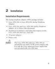
Use only the Cisco-approved power supply that was provided with a 5V DC power adapter only. 2 Installation Installation Requirements The analog telephone adaptor (ATA) package includes: • Cisco ATA 186 or Cisco ATA 188 Analog Telephone Adaptor • Cisco ATA 186 and Cisco ATA 188 Analog Telephone Adaptor At A Glance (this document) • Regulatory Compliance and Safety Information for the Cisco ATA 186 and Cisco ATA 188. • 5V power adaptor • Power cord Caution The Cisco ATA 186 and Cisco ATA 188 are intended for use with your ATA unit. 11
Use only the Cisco-approved power supply that was provided with a 5V DC power adapter only. 2 Installation Installation Requirements The analog telephone adaptor (ATA) package includes: • Cisco ATA 186 or Cisco ATA 188 Analog Telephone Adaptor • Cisco ATA 186 and Cisco ATA 188 Analog Telephone Adaptor At A Glance (this document) • Regulatory Compliance and Safety Information for the Cisco ATA 186 and Cisco ATA 188. • 5V power adaptor • Power cord Caution The Cisco ATA 186 and Cisco ATA 188 are intended for use with your ATA unit. 11

User Guide
Page 12
Otherwise, use a crossover Ethernet cable to connect the Cisco ATA to another Ethernet device (such as a router or PC) without quality degradation. One cable is needed for each 12 A Category-3 Ethernet cable supports 10BASE-T ...
Otherwise, use a crossover Ethernet cable to connect the Cisco ATA to another Ethernet device (such as a router or PC) without quality degradation. One cable is needed for each 12 A Category-3 Ethernet cable supports 10BASE-T ...
User Guide
Page 13
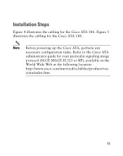
Installation Steps Figure 4 illustrates the cabling for your particular signaling image protocol (SCCP, MGCP, H.323 or SIP), available on the World Wide Web at the following location: http://www.cisco.com/univercd/cc/td/doc/product/voic e/ata/index.htm 13 Note Before powering up the Cisco ATA, perform any necessary configuration tasks. Refer to the Cisco ATA administrator guide for the Cisco ATA 186. Figure 5 illustrates the cabling for the Cisco ATA 188.
Installation Steps Figure 4 illustrates the cabling for your particular signaling image protocol (SCCP, MGCP, H.323 or SIP), available on the World Wide Web at the following location: http://www.cisco.com/univercd/cc/td/doc/product/voic e/ata/index.htm 13 Note Before powering up the Cisco ATA, perform any necessary configuration tasks. Refer to the Cisco ATA administrator guide for the Cisco ATA 186. Figure 5 illustrates the cabling for the Cisco ATA 188.

User Guide
Page 14
72212 Figure 4 Cabling the Cisco ATA 186 PHONE 1 PHONE 2 10BaseT ACT 5V Analog telephones (or fax) IP network 5V power adaptor Power outlet Power cord 14
72212 Figure 4 Cabling the Cisco ATA 186 PHONE 1 PHONE 2 10BaseT ACT 5V Analog telephones (or fax) IP network 5V power adaptor Power outlet Power cord 14
User Guide
Page 15
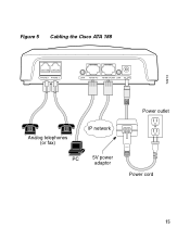
Figure 5 Cabling the Cisco ATA 188 72213 PHONE 1 PHONE 2 LINK 10/100 PC 10/100 UPLINK LINK 5V Analog telephones (or fax) IP network PC 5V power adaptor Power outlet Power cord 15
Figure 5 Cabling the Cisco ATA 188 72213 PHONE 1 PHONE 2 LINK 10/100 PC 10/100 UPLINK LINK 5V Analog telephones (or fax) IP network PC 5V power adaptor Power outlet Power cord 15
User Guide
Page 16
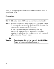
...1 input on the rear panel of fire, use only No. 26 AWG or larger telecommunication line cord. 16 Warning To reduce the risk of the Cisco ATA. Connect the other end to an analog telephone set that was previously connected to install your ATA: Procedure Step 1 Step 2 Place the... Cisco ATA near an electrical power outlet. If you are connecting a telephone set . Refer to the appropriate illustration and follow these steps to an active ...
...1 input on the rear panel of fire, use only No. 26 AWG or larger telecommunication line cord. 16 Warning To reduce the risk of the Cisco ATA. Connect the other end to an analog telephone set that was previously connected to install your ATA: Procedure Step 1 Step 2 Place the... Cisco ATA near an electrical power outlet. If you are connecting a telephone set . Refer to the appropriate illustration and follow these steps to an active ...
User Guide
Page 17
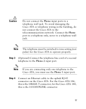
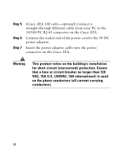
... to a telephone wall jack. Note If you must be switched to operate properly. for the Cisco ATA to tone setting (not pulse) for the Cisco ATA 188, this is the 10/100UPLINK connector. 17 For the Cisco ATA 186, this is the 10BASE-T connector; Step 3 (Optional) Connect the telephone line cord of a ...second telephone to the Cisco ATA, you are connecting only one telephone to the Phone 2 input port. Note The telephone must use the Phone 1 input port. Step 4 Connect an ...
... to a telephone wall jack. Note If you must be switched to operate properly. for the Cisco ATA to tone setting (not pulse) for the Cisco ATA 188, this is the 10/100UPLINK connector. 17 For the Cisco ATA 186, this is the 10BASE-T connector; Step 3 (Optional) Connect the telephone line cord of a ...second telephone to the Cisco ATA, you are connecting only one telephone to the Phone 2 input port. Note The telephone must use the Phone 1 input port. Step 4 Connect an ...
User Guide
Page 18
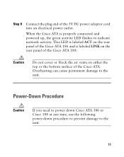
Warning This product relies on the Cisco ATA. Step 5 Step 6 Step 7 (Cisco ATA 188 only-optional) Connect a straight-through Ethernet cable from your PC to the 5V DC power adaptor. Insert the power adaptor cable into the power connector on the phase conductors (all current-carrying conductors). 18 Ensure that a fuse or circuit breaker no larger than 120 VAC, 15A U.S. (240VAC, 10A international) is used on the Cisco ATA. Connect the socket end of the power cord to the 10/100 PC RJ-45 connector on the building's installation for short-circuit (overcurrent) protection.
Warning This product relies on the Cisco ATA. Step 5 Step 6 Step 7 (Cisco ATA 188 only-optional) Connect a straight-through Ethernet cable from your PC to the 5V DC power adaptor. Insert the power adaptor cable into the power connector on the phase conductors (all current-carrying conductors). 18 Ensure that a fuse or circuit breaker no larger than 120 VAC, 15A U.S. (240VAC, 10A international) is used on the Cisco ATA. Connect the socket end of the power cord to the 10/100 PC RJ-45 connector on the building's installation for short-circuit (overcurrent) protection.
User Guide
Page 19
... electrical power outlet. Caution Do not cover or block the air vents on the rear panel of the Cisco ATA 188. Power-Down Procedure Caution If you need to power down Cisco ATA 186 or Cisco 188 at any time, use the following power-down procedure to prevent damage to the unit. 19... Step 8 Connect the plug end of the Cisco ATA. This LED is labeled ACT on the rear panel of the Cisco ATA 186 and is properly connected and powered up, the green activity LED flashes to the unit.
... electrical power outlet. Caution Do not cover or block the air vents on the rear panel of the Cisco ATA 188. Power-Down Procedure Caution If you need to power down Cisco ATA 186 or Cisco 188 at any time, use the following power-down procedure to prevent damage to the unit. 19... Step 8 Connect the plug end of the Cisco ATA. This LED is labeled ACT on the rear panel of the Cisco ATA 186 and is properly connected and powered up, the green activity LED flashes to the unit.
User Guide
Page 20
Each port supports either voice calls or fax sessions, and both ports can connect to any standard analog telephone device. Unplug the power cable. The unit provides the following connectors and indicators: • 5V power connector. • Two RJ-11 FXS (Foreign Exchange Station) ports-The Cisco ATA supports two independent RJ-11 telephone ports that can be used simultaneously. 20 Procedure Step 1 Step 2 Step 3 Unplug the RJ45 Ethernet cable Wait for 20 seconds.
Each port supports either voice calls or fax sessions, and both ports can connect to any standard analog telephone device. Unplug the power cable. The unit provides the following connectors and indicators: • 5V power connector. • Two RJ-11 FXS (Foreign Exchange Station) ports-The Cisco ATA supports two independent RJ-11 telephone ports that can be used simultaneously. 20 Procedure Step 1 Step 2 Step 3 Unplug the RJ45 Ethernet cable Wait for 20 seconds.
User Guide
Page 21
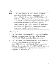
...and should match your country or regional telephone impedance requirements. • Ethernet ports - The Cisco ATA 188 has two Ethernet ports: an RJ-45 10/100BASE-T uplink port to connect the Cisco ATA 188 to a 10/100BASE-T hub or another Ethernet device and an RJ-45 10/...check your specific application. The Cisco ATA186-I2 and Cisco ATA188-I2 provide 270 ohm + 750 ohm // 150-nF complex impedance. The Cisco ATA 186 has one RJ-45 10BASE-T uplink Ethernet port to connect the Cisco ATA 186 to the network. 21 Note The Cisco ATA186-I1 and Cisco ATA188-I1 provide 600-ohm resistive ...
...and should match your country or regional telephone impedance requirements. • Ethernet ports - The Cisco ATA 188 has two Ethernet ports: an RJ-45 10/100BASE-T uplink port to connect the Cisco ATA 188 to a 10/100BASE-T hub or another Ethernet device and an RJ-45 10/...check your specific application. The Cisco ATA186-I2 and Cisco ATA188-I2 provide 270 ohm + 750 ohm // 150-nF complex impedance. The Cisco ATA 186 has one RJ-45 10BASE-T uplink Ethernet port to connect the Cisco ATA 186 to the network. 21 Note The Cisco ATA186-I1 and Cisco ATA188-I1 provide 600-ohm resistive ...
User Guide
Page 22
The LED blinks to show network activity and is solid when there is a link. • The Cisco ATA 186 RJ-45 LED is solid when the Cisco ATA is powered on and blinks to show network activity. • Function button-The function button is fixed at 10 Mbps, half-duplex operation. • ...The Cisco ATA 188 RJ-45 LED shows network link and activity. The Cisco ATA 186 is located on , then turns off if there is capable of the unit (see Figure 6). 22 The LED...
The LED blinks to show network activity and is solid when there is a link. • The Cisco ATA 186 RJ-45 LED is solid when the Cisco ATA is powered on and blinks to show network activity. • Function button-The function button is fixed at 10 Mbps, half-duplex operation. • ...The Cisco ATA 188 RJ-45 LED shows network link and activity. The Cisco ATA 186 is located on , then turns off if there is capable of the unit (see Figure 6). 22 The LED...

User Guide
Page 23
The button blinks quickly when the Cisco ATA is available. 23 Check your Ethernet connections and make sure the DHCP server is upgrading its configuration. Note If the function button blinks slowly, the Cisco ATA cannot find the DHCP server. Figure 6 Cisco ATA Function Button Function button 72214 ANALOCGISTCELOEPAHTONAE1A8D6APTOR The function button lights when you pick up the handset of a telephone attached to the Cisco ATA.
The button blinks quickly when the Cisco ATA is available. 23 Check your Ethernet connections and make sure the DHCP server is upgrading its configuration. Note If the function button blinks slowly, the Cisco ATA cannot find the DHCP server. Figure 6 Cisco ATA Function Button Function button 72214 ANALOCGISTCELOEPAHTONAE1A8D6APTOR The function button lights when you pick up the handset of a telephone attached to the Cisco ATA.