
Installation Guide
Page 1
... or in a Rack, page 6-14 • Attaching the Cable-Management Brackets, page 6-18 • Attaching a Chassis Ground Connection, page 6-19 • Connecting the Shared Port Adapter Cables, page 6-21 • Connecting the Console and Auxiliary Port Cables, page 6-22 • Connecting Power to the Cisco ASR 1006 Router, page 6-23 • Connecting a Terminal to connect interface and power cables. It is designed with a single midplane with a Cisco ASR1000-RP2) OL-13208-09 Cisco ASR 1000 Series Aggregation Services Routers Hardware Installation Guide 6-1 This...
... or in a Rack, page 6-14 • Attaching the Cable-Management Brackets, page 6-18 • Attaching a Chassis Ground Connection, page 6-19 • Connecting the Shared Port Adapter Cables, page 6-21 • Connecting the Console and Auxiliary Port Cables, page 6-22 • Connecting Power to the Cisco ASR 1006 Router, page 6-23 • Connecting a Terminal to connect interface and power cables. It is designed with a single midplane with a Cisco ASR1000-RP2) OL-13208-09 Cisco ASR 1000 Series Aggregation Services Routers Hardware Installation Guide 6-1 This...
Installation Guide
Page 2
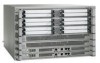
.... Cisco ASR 1006 Router Description Chapter 6 Cisco ASR 1006 Router Overview and Installation • Two Cisco ASR 1000 Series Route Processors (Cisco ASR1000-RP1 or Cisco ASR1000-RP2) • Dual (redundant) AC and DC power supplies This section contains the following topics: • Front View, page 6-2 • Rear View, page 6-3 Front View Figure 6-1 shows the Cisco ASR 1006 Router with ASR 1000 Series ESP 5 ASR 1000 Series SIP slot 0 6 ASR 1000 Series SIP slot 1 7 ASR 1000 Series SIP slot 2 280032 Cisco ASR 1000 Series Aggregation Services Routers Hardware Installation Guide...
.... Cisco ASR 1006 Router Description Chapter 6 Cisco ASR 1006 Router Overview and Installation • Two Cisco ASR 1000 Series Route Processors (Cisco ASR1000-RP1 or Cisco ASR1000-RP2) • Dual (redundant) AC and DC power supplies This section contains the following topics: • Front View, page 6-2 • Rear View, page 6-3 Front View Figure 6-1 shows the Cisco ASR 1006 Router with ASR 1000 Series ESP 5 ASR 1000 Series SIP slot 0 6 ASR 1000 Series SIP slot 1 7 ASR 1000 Series SIP slot 2 280032 Cisco ASR 1000 Series Aggregation Services Routers Hardware Installation Guide...

Installation Guide
Page 3
... and DC power supplies in the router. OL-13208-09 Cisco ASR 1000 Series Aggregation Services Routers Hardware Installation Guide 6-3 For a description of handling alarm conditions in the same chassis. Note You have more than one power supply connection. All connections must be removed to de-energize the unit. 4 3 2 1 1 AC power supply fan 5 AC power supply handle 2 AC power supply DB-25 alarm connector-A 6 AC power inlet female DB-25 sub connector which enables you to...
... and DC power supplies in the router. OL-13208-09 Cisco ASR 1000 Series Aggregation Services Routers Hardware Installation Guide 6-3 For a description of handling alarm conditions in the same chassis. Note You have more than one power supply connection. All connections must be removed to de-energize the unit. 4 3 2 1 1 AC power supply fan 5 AC power supply handle 2 AC power supply DB-25 alarm connector-A 6 AC power inlet female DB-25 sub connector which enables you to...

Installation Guide
Page 6
... a wall or cabinet for normal operation and pull it after the chassis is recommended to remove field-replaceable units. • Maintain a minimum clearance of 3 inches (7.62 cm) for maintenance. otherwise, the heated exhaust air from the chassis to another equipment rack; Figure 6-4 Cisco ASR 1006 Router - Cisco ASR 1000 Series Aggregation Services Routers Hardware Installation Guide 6-6 OL-13208-09 However, you can enter the inlet air vents...
... a wall or cabinet for normal operation and pull it after the chassis is recommended to remove field-replaceable units. • Maintain a minimum clearance of 3 inches (7.62 cm) for maintenance. otherwise, the heated exhaust air from the chassis to another equipment rack; Figure 6-4 Cisco ASR 1006 Router - Cisco ASR 1000 Series Aggregation Services Routers Hardware Installation Guide 6-6 OL-13208-09 However, you can enter the inlet air vents...

Installation Guide
Page 7
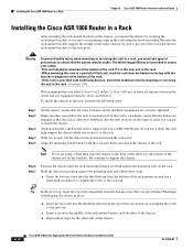
... to prevent the rack from other equipment already installed in the rack do not impair access to the cards or require you to disconnect cables unnecessarily to perform equipment maintenance or upgrades. • Install rack stabilizers (if available) before you mount the chassis. • Provide an adequate chassis ground (earth) connection for your router chassis. Table 6-1 provides the Cisco ASR 1006 Router dimensions and weight information. fully configured Guidelines for avoiding...
... to prevent the rack from other equipment already installed in the rack do not impair access to the cards or require you to disconnect cables unnecessarily to perform equipment maintenance or upgrades. • Install rack stabilizers (if available) before you mount the chassis. • Provide an adequate chassis ground (earth) connection for your router chassis. Table 6-1 provides the Cisco ASR 1006 Router dimensions and weight information. fully configured Guidelines for avoiding...

Installation Guide
Page 8
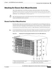
... surrounding area. Use at least 4 screws to secure the rack-mount brackets to lift the chassis onto a tabletop or platform. Repeat Step 2 through Step 3 on the other side of how to one side. Locate the threaded holes in Figure 6-5 does not represent the Cisco ASR 1000 Series Router. Cisco ASR 1000 Series Aggregation Services Routers Hardware Installation Guide 6-8 OL-13208-09 Align the front rack-mount bracket to lift a Cisco chassis.
... surrounding area. Use at least 4 screws to secure the rack-mount brackets to lift the chassis onto a tabletop or platform. Repeat Step 2 through Step 3 on the other side of how to one side. Locate the threaded holes in Figure 6-5 does not represent the Cisco ASR 1000 Series Router. Cisco ASR 1000 Series Aggregation Services Routers Hardware Installation Guide 6-8 OL-13208-09 Align the front rack-mount bracket to lift a Cisco chassis.
Installation Guide
Page 9
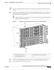
... are securely tightened. Figure 6-6 shows the cable-management brackets attached on the front of the rack-mount brackets already attached to each cable-management bracket, use two screws from the package of four screws. Figure 6-6 Attaching the Cable-Management Brackets to the chassis. Note Make certain that all the screws are installed on a table top or equipment shelf. OL-13208-09 Cisco ASR 1000 Series Aggregation Services Routers Hardware Installation Guide...
... are securely tightened. Figure 6-6 shows the cable-management brackets attached on the front of the rack-mount brackets already attached to each cable-management bracket, use two screws from the package of four screws. Figure 6-6 Attaching the Cable-Management Brackets to the chassis. Note Make certain that all the screws are installed on a table top or equipment shelf. OL-13208-09 Cisco ASR 1000 Series Aggregation Services Routers Hardware Installation Guide...

Installation Guide
Page 10
... a Chassis Ground Connection" section on page 6-19 for pairs of holes near the bottom, middle and top of the left and right mounting rails. The chassis rack-mounting flanges are parallel. Rack-Mounting the Cisco ASR 1006 Router Chapter 6 Cisco ASR 1006 Router Overview and Installation Step 8 Go to hole centerline 18.31 inches ± 0.06 inches (46.5 cm ± 0.15 cm) 28014 6-10 Cisco ASR 1000 Series Aggregation Services Routers Hardware Installation Guide OL...
... a Chassis Ground Connection" section on page 6-19 for pairs of holes near the bottom, middle and top of the left and right mounting rails. The chassis rack-mounting flanges are parallel. Rack-Mounting the Cisco ASR 1006 Router Chapter 6 Cisco ASR 1006 Router Overview and Installation Step 8 Go to hole centerline 18.31 inches ± 0.06 inches (46.5 cm ± 0.15 cm) 28014 6-10 Cisco ASR 1000 Series Aggregation Services Routers Hardware Installation Guide OL...
Installation Guide
Page 11
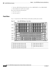
...A/L C/A A/L C/A A/L C/A A/L C/A A/L C/A A/L C/A 3 A/L C/A 3 A/L C/A 3 A/L C/A 3 A/L C/A 3 A/L C/A 3 A/L C/A Cisco ASR 1006 SPA-4XOC3-POS STATUS STATUS SPA-4XOC3-POS 2 STATUS SPA-4XOC3-POS STATUS SPA-4XOC3-POS 1 STATUS SPA-4XOC3-POS SPA-4XOC3-POS STATUS 0 F1 F0 R1 R0 280035 1 Front rack-mount bracket screws 2 Front rack-mount bracket 4 32 1 3 Front rack-mount bracket ear and holes 4 Chassis side vent location Cisco ASR 1000 Series Aggregation Services Routers Hardware Installation Guide 6-11 Depending on the bracket holes you hold the front rack-mount bracket...
...A/L C/A A/L C/A A/L C/A A/L C/A A/L C/A A/L C/A 3 A/L C/A 3 A/L C/A 3 A/L C/A 3 A/L C/A 3 A/L C/A 3 A/L C/A Cisco ASR 1006 SPA-4XOC3-POS STATUS STATUS SPA-4XOC3-POS 2 STATUS SPA-4XOC3-POS STATUS SPA-4XOC3-POS 1 STATUS SPA-4XOC3-POS SPA-4XOC3-POS STATUS 0 F1 F0 R1 R0 280035 1 Front rack-mount bracket screws 2 Front rack-mount bracket 4 32 1 3 Front rack-mount bracket ear and holes 4 Chassis side vent location Cisco ASR 1000 Series Aggregation Services Routers Hardware Installation Guide 6-11 Depending on the bracket holes you hold the front rack-mount bracket...
Installation Guide
Page 12
... 6-14. Install the chassis in a Rack" section on one side. To install the Cisco ASR 1006 Router in a rack, go to the "Installing the Cisco ASR 1006 Router in the rack. Make certain that you are rack-mounting the chassis using the rear rack-mount brackets, then this type of the chassis. 6-12 Cisco ASR 1000 Series Aggregation Services Routers Hardware Installation Guide OL-13208-09 Attaching the Chassis Rack-Mount Brackets Chapter 6 Cisco ASR 1006 Router Overview and Installation Step 2 Step 3 Step 4 Step 5 Position the front rack-mount bracket top...
... 6-14. Install the chassis in a Rack" section on one side. To install the Cisco ASR 1006 Router in a rack, go to the "Installing the Cisco ASR 1006 Router in the rack. Make certain that you are rack-mounting the chassis using the rear rack-mount brackets, then this type of the chassis. 6-12 Cisco ASR 1000 Series Aggregation Services Routers Hardware Installation Guide OL-13208-09 Attaching the Chassis Rack-Mount Brackets Chapter 6 Cisco ASR 1006 Router Overview and Installation Step 2 Step 3 Step 4 Step 5 Position the front rack-mount bracket top...

Installation Guide
Page 13
... a rack, make certain you mount the Cisco ASR 1006 Router on the other side of the chassis, slide the two remaining components into rear bracket attached to the Cisco ASR 1006 Router 12 1 3 1 0 0 280038 4 1 Rear rack-mount bracket ear and holes 2 Rear rack-mount bracket 3 Rear rack-mount bracket components that slide into the side rack-mount bracket. OL-13208-09 Cisco ASR 1000 Series Aggregation Services Routers Hardware Installation Guide 6-13 Caution Before you read which rack-mount...
... a rack, make certain you mount the Cisco ASR 1006 Router on the other side of the chassis, slide the two remaining components into rear bracket attached to the Cisco ASR 1006 Router 12 1 3 1 0 0 280038 4 1 Rear rack-mount bracket ear and holes 2 Rear rack-mount bracket 3 Rear rack-mount bracket components that slide into the side rack-mount bracket. OL-13208-09 Cisco ASR 1000 Series Aggregation Services Routers Hardware Installation Guide 6-13 Caution Before you read which rack-mount...
Installation Guide
Page 14
... 2 inches (2.54 or 5.08 cm) of the rack-mount bracket on the installed components are using the screws provided. Because the rack-mount brackets support the weight of the rack-mount ear and tighten the screw to the rack. If you use all screw fasteners on both sides of the chassis. 6-14 Cisco ASR 1000 Series Aggregation Services Routers Hardware Installation Guide OL-13208-09 Insert the top screw into...
... 2 inches (2.54 or 5.08 cm) of the rack-mount bracket on the installed components are using the screws provided. Because the rack-mount brackets support the weight of the rack-mount ear and tighten the screw to the rack. If you use all screw fasteners on both sides of the chassis. 6-14 Cisco ASR 1000 Series Aggregation Services Routers Hardware Installation Guide OL-13208-09 Insert the top screw into...

Installation Guide
Page 15
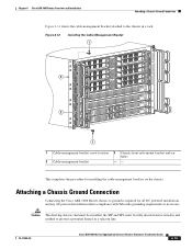
... LINK BITS MGMT ETHERNET CON AUX CON AUX A/L C/A A/L C/A A/L C/A A/L C/A A/L C/A A/L C/A 2 2 2 2 2 2 A/L C/A A/L C/A A/L C/A A/L C/A A/L C/A A/L C/A 3 A/L C/A 3 A/L C/A 3 A/L C/A 3 A/L C/A 3 A/L C/A 3 A/L C/A Cisco ASR 1006 SPA-4XOC3-POS STATUS STATUS SPA-4XOC3-POS 2 STATUS SPA-4XOC3-POS STATUS SPA-4XOC3-POS 1 STATUS SPA-4XOC3-POS SPA-4XOC3-POS STATUS 0 F1 F0 R1 R0 2 1 280085 1 Cisco ASR 1006 Router front rack-mount bracket 2 Two-post equipment rack rail OL-13208-09 Cisco ASR 1000 Series Aggregation Services Routers Hardware Installation Guide...
... LINK BITS MGMT ETHERNET CON AUX CON AUX A/L C/A A/L C/A A/L C/A A/L C/A A/L C/A A/L C/A 2 2 2 2 2 2 A/L C/A A/L C/A A/L C/A A/L C/A A/L C/A A/L C/A 3 A/L C/A 3 A/L C/A 3 A/L C/A 3 A/L C/A 3 A/L C/A 3 A/L C/A Cisco ASR 1006 SPA-4XOC3-POS STATUS STATUS SPA-4XOC3-POS 2 STATUS SPA-4XOC3-POS STATUS SPA-4XOC3-POS 1 STATUS SPA-4XOC3-POS SPA-4XOC3-POS STATUS 0 F1 F0 R1 R0 2 1 280085 1 Cisco ASR 1006 Router front rack-mount bracket 2 Two-post equipment rack rail OL-13208-09 Cisco ASR 1000 Series Aggregation Services Routers Hardware Installation Guide...
Installation Guide
Page 19
... SPA-4XOC3-POS STATUS STATUS A/L C/A 3 A/L C/A 2 1 0 280036 2 1 1 Cable-management bracket screw location 3 Chassis front rack-mount bracket and ear holes 2 Cable-management bracket -- Caution The dual-lug chassis stud must be installed, the SIP and SPA must be fully inserted and screwed in and earthed to the chassis in a telecom line. Attaching a Chassis Ground Connection Connecting the Cisco ASR 1006 Router chassis to ground is necessary. OL-13208-09 Cisco ASR 1000 Series Aggregation Services Routers Hardware Installation Guide 6-19
... SPA-4XOC3-POS STATUS STATUS A/L C/A 3 A/L C/A 2 1 0 280036 2 1 1 Cable-management bracket screw location 3 Chassis front rack-mount bracket and ear holes 2 Cable-management bracket -- Caution The dual-lug chassis stud must be installed, the SIP and SPA must be fully inserted and screwed in and earthed to the chassis in a telecom line. Attaching a Chassis Ground Connection Connecting the Cisco ASR 1006 Router chassis to ground is necessary. OL-13208-09 Cisco ASR 1000 Series Aggregation Services Routers Hardware Installation Guide 6-19
Installation Guide
Page 22
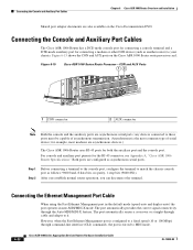
...chassis. Connecting the Ethernet Management Port Cable When using the Fast Ethernet Management port in the default mode (speed-auto and duplex-auto) the port operates in auto-MDI/MDI-X mode. Connecting the Console and Auxiliary Port Cables Chapter 6 Cisco ASR 1006 Router Overview and Installation Shared port adapter documents are also available on the Cisco ASR 1000 Series route processor card. Both ports are configured as another router) to it. However, when the Fast Ethernet Management port is configured to a fixed speed (10 or 100 Mbps) through command-line interface (CLI) commands...
...chassis. Connecting the Ethernet Management Port Cable When using the Fast Ethernet Management port in the default mode (speed-auto and duplex-auto) the port operates in auto-MDI/MDI-X mode. Connecting the Console and Auxiliary Port Cables Chapter 6 Cisco ASR 1006 Router Overview and Installation Shared port adapter documents are also available on the Cisco ASR 1000 Series route processor card. Both ports are configured as another router) to it. However, when the Fast Ethernet Management port is configured to a fixed speed (10 or 100 Mbps) through command-line interface (CLI) commands...

Installation Guide
Page 23
...-09 Cisco ASR 1000 Series Aggregation Services Routers Hardware Installation Guide 6-23 Statement 1003 Warning Only trained and qualified personnel should be made first and disconnected last. Chapter 6 Cisco ASR 1006 Router Overview and Installation Connecting Power to the Cisco ASR 1006 Router When in a fixed-speed configuration and MDI mode: • Use a crossover cable to connect to an MDI port • Use a straight-through cable to connect to an MDI-X port Connecting Power to the Cisco ASR 1006 Router Warning The covers are an integral part...
...-09 Cisco ASR 1000 Series Aggregation Services Routers Hardware Installation Guide 6-23 Statement 1003 Warning Only trained and qualified personnel should be made first and disconnected last. Chapter 6 Cisco ASR 1006 Router Overview and Installation Connecting Power to the Cisco ASR 1006 Router When in a fixed-speed configuration and MDI mode: • Use a crossover cable to connect to an MDI port • Use a straight-through cable to connect to an MDI-X port Connecting Power to the Cisco ASR 1006 Router Warning The covers are an integral part...

Installation Guide
Page 24
... power cable into the inlet. In the Cisco ASR 1006 Router, at least one PEM must be powered on page 13-41. Note Detailed instructions for removing and replacing the Cisco ASR 1000 Series AC and DC power supplies are sufficient to the Cisco 1006 chassis: Step 1 At the rear of the chassis, check whether the power switch on page A-1. Note All Cisco ASR 1000 Series Router AC power supplies must be increased. Connecting Power to the Cisco ASR 1006 Router Chapter 6 Cisco ASR 1006 Router Overview and Installation...
... power cable into the inlet. In the Cisco ASR 1006 Router, at least one PEM must be powered on page 13-41. Note Detailed instructions for removing and replacing the Cisco ASR 1000 Series AC and DC power supplies are sufficient to the Cisco 1006 chassis: Step 1 At the rear of the chassis, check whether the power switch on page A-1. Note All Cisco ASR 1000 Series Router AC power supplies must be increased. Connecting Power to the Cisco ASR 1006 Router Chapter 6 Cisco ASR 1006 Router Overview and Installation...
Installation Guide
Page 29
... Panduit part number: - Statement 1046 To connect the DC power supply, follow these steps: Step 1 Step 2 Make certain that you install the unit, the ground connection must verify the polarity by a cable lug. The ground wire cable lug should be able to fit over M6 terminal studs at least 6-AWG multistrand copper wire. Chapter 6 Cisco ASR 1006 Router Overview and Installation Connecting Power to the Cisco ASR 1006 Router Each...
... Panduit part number: - Statement 1046 To connect the DC power supply, follow these steps: Step 1 Step 2 Make certain that you install the unit, the ground connection must verify the polarity by a cable lug. The ground wire cable lug should be able to fit over M6 terminal studs at least 6-AWG multistrand copper wire. Chapter 6 Cisco ASR 1006 Router Overview and Installation Connecting Power to the Cisco ASR 1006 Router Each...
Installation Guide
Page 35
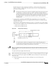
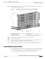
... system. Connecting the System Cables Keep the following default console port settings: 9600 baud, 8 data bits, No parity generation or checking, 1 stop bit, and No flow control. Power on page 6-35 to continue the installation. Chapter 6 Cisco ASR 1006 Router Overview and Installation Connecting the System Cables Step 2 Run the cable up and through the cable-management bracket and connect the other end of interference, avoid crossing high-power lines with Cabling in the Cisco ASR 1006 Router STATUS A/L C/A A/L C/A A/L C/A STATUS A/L C/A A/L C/A A/L C/A 3 A/L C/A STATUS...
... system. Connecting the System Cables Keep the following default console port settings: 9600 baud, 8 data bits, No parity generation or checking, 1 stop bit, and No flow control. Power on page 6-35 to continue the installation. Chapter 6 Cisco ASR 1006 Router Overview and Installation Connecting the System Cables Step 2 Run the cable up and through the cable-management bracket and connect the other end of interference, avoid crossing high-power lines with Cabling in the Cisco ASR 1006 Router STATUS A/L C/A A/L C/A A/L C/A STATUS A/L C/A A/L C/A A/L C/A 3 A/L C/A STATUS...
Installation Guide
Page 36
... ETHERNET BITS AUX CON 1 CONsole port 2 AUXiliary port Step 2 Run the cable up and through the cable-management bracket U feature device as shown in Figure 6-27, and connect the other end of the modem cable to the RJ-45 port on the primary Cisco ASR 1000 Series Route Processor 1, labeled AUX. Step 1 Connect one end of the cable to Chapter 12, "Cisco ASR 1000 Series Routers Power Up and Initial Configuration." 6-36 Cisco ASR 1000 Series Aggregation Services Routers Hardware Installation Guide...
... ETHERNET BITS AUX CON 1 CONsole port 2 AUXiliary port Step 2 Run the cable up and through the cable-management bracket U feature device as shown in Figure 6-27, and connect the other end of the modem cable to the RJ-45 port on the primary Cisco ASR 1000 Series Route Processor 1, labeled AUX. Step 1 Connect one end of the cable to Chapter 12, "Cisco ASR 1000 Series Routers Power Up and Initial Configuration." 6-36 Cisco ASR 1000 Series Aggregation Services Routers Hardware Installation Guide...


