
Installation Guide
Page 6
... and Cable Guides on the Catalyst 6503 and the Catalyst 6503-E Switches 3-8 Installing the L Brackets and Cable Guides on the Catalyst 6504-E Switch 3-10 Installing the L Brackets and Cable Guides on the Catalyst 6506 and Catalyst 6506-E Switches 3-11 Installing the L Brackets and Cable Guides on the Catalyst 6509 and Catalyst 6509-E Switches 3-13 Installing the L Brackets and Cable Guides on the Catalyst 6509-NEB Switch 3-15 Installing the L Brackets on the Catalyst 6509-NEB-A Switch 3-17 Installing the Switch Chassis...
... and Cable Guides on the Catalyst 6503 and the Catalyst 6503-E Switches 3-8 Installing the L Brackets and Cable Guides on the Catalyst 6504-E Switch 3-10 Installing the L Brackets and Cable Guides on the Catalyst 6506 and Catalyst 6506-E Switches 3-11 Installing the L Brackets and Cable Guides on the Catalyst 6509 and Catalyst 6509-E Switches 3-13 Installing the L Brackets and Cable Guides on the Catalyst 6509-NEB Switch 3-15 Installing the L Brackets on the Catalyst 6509-NEB-A Switch 3-17 Installing the Switch Chassis...
Installation Guide
Page 7
...Cable Management System (Catalyst 6509-NEB-A Switch Only) 3-23 Replacing the Cable Guide 3-25 Establishing the System Ground 3-27 Required Tools and Parts 3-28 Connecting the System Ground 3-29 Installing the Power Supplies in the Switch Chassis 3-34 Attaching the Interface Cables 3-34 Connecting the Supervisor Engine Console Port 3-34 Connecting the Supervisor Engine Uplink Ports 3-36 Verifying Switch Chassis... 4-65 Checking the Installation 4-65 Installing the Air Filter Assembly on a Catalyst 6509-NEB-A Switch (Optional) 4-66 OL-5781-04 Catalyst 6500 Series Switches Installation Guide vii
...Cable Management System (Catalyst 6509-NEB-A Switch Only) 3-23 Replacing the Cable Guide 3-25 Establishing the System Ground 3-27 Required Tools and Parts 3-28 Connecting the System Ground 3-29 Installing the Power Supplies in the Switch Chassis 3-34 Attaching the Interface Cables 3-34 Connecting the Supervisor Engine Console Port 3-34 Connecting the Supervisor Engine Uplink Ports 3-36 Verifying Switch Chassis... 4-65 Checking the Installation 4-65 Installing the Air Filter Assembly on a Catalyst 6509-NEB-A Switch (Optional) 4-66 OL-5781-04 Catalyst 6500 Series Switches Installation Guide vii
Installation Guide
Page 46
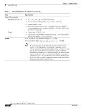
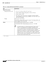
...)-420 CFM. WS-C6K-6SLOT-FAN (Standard fan tray)-227 CFM. Catalyst 6506 Switch Chapter 1 Product Overview Table 1-8 Catalyst 6506 Switch Specifications (continued) Item Physical Characteristics Dimensions (H x W x D) Weight Airflow Specification • 20.1 x 17.2 x 18.1 in. (51.1 x 43.7 x 46.0 cm). • Chassis depth including cable guide is 21.64 in standard 19-inch equipment racks that you maintain...
...)-420 CFM. WS-C6K-6SLOT-FAN (Standard fan tray)-227 CFM. Catalyst 6506 Switch Chapter 1 Product Overview Table 1-8 Catalyst 6506 Switch Specifications (continued) Item Physical Characteristics Dimensions (H x W x D) Weight Airflow Specification • 20.1 x 17.2 x 18.1 in. (51.1 x 43.7 x 46.0 cm). • Chassis depth including cable guide is 21.64 in standard 19-inch equipment racks that you maintain...
Installation Guide
Page 51
... strap (redundant) connector 113673 Catalyst 6500 Series Switches Installation Guide 1-27 Chapter 1 Product Overview Catalyst 6506-E Switch Table 1-10 Catalyst 6506-E Switch Specifications (continued) Item Physical Characteristics Dimensions (H x W x D) Weight Airflow Specification • 19.2 x 17.5 x 18.2 in. (48.8 x 44.5 x 46.0 cm). • Chassis depth including cable guide is designed to prevent overheating. Chassis fully configured with 1 supervisor engine, 5 switching modules, and 2 power supplies...
... strap (redundant) connector 113673 Catalyst 6500 Series Switches Installation Guide 1-27 Chapter 1 Product Overview Catalyst 6506-E Switch Table 1-10 Catalyst 6506-E Switch Specifications (continued) Item Physical Characteristics Dimensions (H x W x D) Weight Airflow Specification • 19.2 x 17.5 x 18.2 in. (48.8 x 44.5 x 46.0 cm). • Chassis depth including cable guide is designed to prevent overheating. Chassis fully configured with 1 supervisor engine, 5 switching modules, and 2 power supplies...
Installation Guide
Page 56
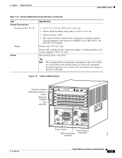
... designed to install in . (55.0 cm). • Chassis requires 15 RU1. • The Catalyst 6509 switch chassis is from front to fail. Catalyst 6509 Switch Chapter 1 Product Overview Table 1-12 Catalyst 6509 Switch Specifications (continued) Item Physical Characteristics Dimensions (H x W x D) Weight Airflow Specification • 25.2 x 17.2 x 18.4 in. (64.0 x 43.7 x 46.7 cm). • Chassis depth including cable guide is 21.64 in standard 19-inch...
... designed to install in . (55.0 cm). • Chassis requires 15 RU1. • The Catalyst 6509 switch chassis is from front to fail. Catalyst 6509 Switch Chapter 1 Product Overview Table 1-12 Catalyst 6509 Switch Specifications (continued) Item Physical Characteristics Dimensions (H x W x D) Weight Airflow Specification • 25.2 x 17.2 x 18.4 in. (64.0 x 43.7 x 46.7 cm). • Chassis depth including cable guide is 21.64 in standard 19-inch...
Installation Guide
Page 61
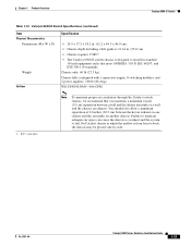
Chapter 1 Product Overview Catalyst 6509-E Switch Table 1-14 Catalyst 6509-E Switch Specifications (continued) Item Physical Characteristics Dimensions (H x W x D) Weight Airflow Specification • 24.5 x 17.5 x 18.2 in. (62.2 x 44.5 x 46.0 cm). • Chassis depth including cable guide is 21.64 in. (55.0 cm). • Chassis requires 15 RU1. • The Catalyst 6509-E switch chassis is from front to back, the chassis may be placed side-by-side. WS...
Chapter 1 Product Overview Catalyst 6509-E Switch Table 1-14 Catalyst 6509-E Switch Specifications (continued) Item Physical Characteristics Dimensions (H x W x D) Weight Airflow Specification • 24.5 x 17.5 x 18.2 in. (62.2 x 44.5 x 46.0 cm). • Chassis depth including cable guide is 21.64 in. (55.0 cm). • Chassis requires 15 RU1. • The Catalyst 6509-E switch chassis is from front to back, the chassis may be placed side-by-side. WS...

Installation Guide
Page 110
... Shelf bracket Shelf bracket 48123 M3 screw Crossbar bracket M3 screw Installing the L Brackets and Cable Guides on the Catalyst 6503 and the Catalyst 6503-E Switches Note The Catalyst 6503 and the Catalyst 6503-E switch chassis are normally shipped with four M3 screws. You attach the optional cable guides by sandwiching them to install the L brackets on each side). If the...
... Shelf bracket Shelf bracket 48123 M3 screw Crossbar bracket M3 screw Installing the L Brackets and Cable Guides on the Catalyst 6503 and the Catalyst 6503-E Switches Note The Catalyst 6503 and the Catalyst 6503-E switch chassis are normally shipped with four M3 screws. You attach the optional cable guides by sandwiching them to install the L brackets on each side). If the...

Installation Guide
Page 111
...04 Catalyst 6500 Series Switches Installation Guide 3-7 The L brackets attach to the rear of the chassis. You attach the optional cable guides by sandwiching them to the Catalyst 6504-E switch chassis using six M4 Phillips countersunk-head screws (three M4 screws on the front of the Catalyst 6504-E switch chassis, perform...PORT 3 ACTIVE TX RX CARARLIEARRM RX TX PORT4 Installing the L Brackets and Cable Guides on your Catalyst 6504-E switch chassis. Repeat Steps 1 and 2 for the other bracket. If the chassis does not have the L brackets installed, follow the steps in this section...
...04 Catalyst 6500 Series Switches Installation Guide 3-7 The L brackets attach to the rear of the chassis. You attach the optional cable guides by sandwiching them to the Catalyst 6504-E switch chassis using six M4 Phillips countersunk-head screws (three M4 screws on the front of the Catalyst 6504-E switch chassis, perform...PORT 3 ACTIVE TX RX CARARLIEARRM RX TX PORT4 Installing the L Brackets and Cable Guides on your Catalyst 6504-E switch chassis. Repeat Steps 1 and 2 for the other bracket. If the chassis does not have the L brackets installed, follow the steps in this section...

Installation Guide
Page 112
... and the switch chassis. Repeat steps 1 and 2 for the Catalyst 6506 and Catalyst 6506-E switches are stamped with four M3 screws. Installing the Rack-Mount Kit Figure 3-4 Installing the L-Brackets on the Catalyst 6504-E Switch Chassis FAN STATUS STATUS STATUS Chapter 3 Installing the Switch 126562 Installing the L Brackets and Cable Guides on your Catalyst 6506 or Catalyst 6506-E switch chassis. Catalyst 6500 Series Switches Installation Guide 3-8 OL-5781...
... and the switch chassis. Repeat steps 1 and 2 for the Catalyst 6506 and Catalyst 6506-E switches are stamped with four M3 screws. Installing the Rack-Mount Kit Figure 3-4 Installing the L-Brackets on the Catalyst 6504-E Switch Chassis FAN STATUS STATUS STATUS Chapter 3 Installing the Switch 126562 Installing the L Brackets and Cable Guides on your Catalyst 6506 or Catalyst 6506-E switch chassis. Catalyst 6500 Series Switches Installation Guide 3-8 OL-5781...

Installation Guide
Page 113
... the Rack-Mount Kit Figure 3-5 Attaching L Brackets and Cable Guides: Catalyst 6506 and Catalyst 6506-E Switch L-bracket 1 2 3 4 FAN STATUS 5 6 WS-X6K-SUP2-2GE STATUS SYSTEMCONSOLPEWR MGRMETSET SUPERVISOR2 WS-X6K-SUP2-2GE CONSOLE STATUS SYSTEMCONSOLPEWR MGRMETSET SUPERVISOR2 CONSOLE WS-X6408 1 CONSOLE PORT ... LINK LINK LINK LINK LINK LINK LINK LINK LINK LINK LINK LINK LINK LINK LINK LINK LINK LINK LINK 12 x 24 or 10 x 32 (10x) Cable guide 113975 OL-5781-04 Catalyst 6500 Series Switches Installation Guide 3-9
... the Rack-Mount Kit Figure 3-5 Attaching L Brackets and Cable Guides: Catalyst 6506 and Catalyst 6506-E Switch L-bracket 1 2 3 4 FAN STATUS 5 6 WS-X6K-SUP2-2GE STATUS SYSTEMCONSOLPEWR MGRMETSET SUPERVISOR2 WS-X6K-SUP2-2GE CONSOLE STATUS SYSTEMCONSOLPEWR MGRMETSET SUPERVISOR2 CONSOLE WS-X6408 1 CONSOLE PORT ... LINK LINK LINK LINK LINK LINK LINK LINK LINK LINK LINK LINK LINK LINK LINK LINK LINK LINK LINK 12 x 24 or 10 x 32 (10x) Cable guide 113975 OL-5781-04 Catalyst 6500 Series Switches Installation Guide 3-9

Installation Guide
Page 114
... necessary, the optional cable guide). 3-10 Catalyst 6500 Series Switches Installation Guide OL-5781-04 If a chassis does not have the L brackets installed, follow these steps: Step 1 Step 2 Step 3 Position the left and right. Installing the Rack-Mount Kit Chapter 3 Installing the Switch Installing the L Brackets and Cable Guides on the Catalyst 6509 and Catalyst 6509-E Switches Note The Catalyst 6509 and Catalyst 6509-E switch chassis are stamped with five...
... necessary, the optional cable guide). 3-10 Catalyst 6500 Series Switches Installation Guide OL-5781-04 If a chassis does not have the L brackets installed, follow these steps: Step 1 Step 2 Step 3 Position the left and right. Installing the Rack-Mount Kit Chapter 3 Installing the Switch Installing the L Brackets and Cable Guides on the Catalyst 6509 and Catalyst 6509-E Switches Note The Catalyst 6509 and Catalyst 6509-E switch chassis are stamped with five...

Installation Guide
Page 115
... LINK 22 LINK 23 LINK 24 LINK 12 x 24 or 10 x 32 (10x) Cable guide o o INPUT OK FAN OUTPUT OK FAIL INPUT OK FAN OUTPUT OK FAIL 113976 Installing the L Brackets and Cable Guides on the Catalyst 6509-NEB Switch Note The Catalyst 6509-NEB switch chassis is normally shipped with ten M4 Phillips countersunk-head screws (five screws on each...
... LINK 22 LINK 23 LINK 24 LINK 12 x 24 or 10 x 32 (10x) Cable guide o o INPUT OK FAN OUTPUT OK FAIL INPUT OK FAN OUTPUT OK FAIL 113976 Installing the L Brackets and Cable Guides on the Catalyst 6509-NEB Switch Note The Catalyst 6509-NEB switch chassis is normally shipped with ten M4 Phillips countersunk-head screws (five screws on each...

Installation Guide
Page 116
set of holes for the first L bracket, use the - Figure 3-7 Attaching L Brackets and Cable Guides: Catalyst 6509-NEB Switch L bracket L bracket WS-X6408 WS-X6K-SUP2-2GE STATUSSYSTEMCONSOLPEWR MGRMETSET SUPERVISOR2 WS-X6K-SUP2-2GE STATUSSYSTEMCONSOLPEWR ...Installing the Switch The optional cable guide installs on the front of the chassis and is secured with five M4 screws. holes.) Secure the L bracket to the switch chassis with four M4 screws. To install the optional cable guide, follow these steps: Step 1 Step 2 Position the cable guide against the switch chassis side, ...
set of holes for the first L bracket, use the - Figure 3-7 Attaching L Brackets and Cable Guides: Catalyst 6509-NEB Switch L bracket L bracket WS-X6408 WS-X6K-SUP2-2GE STATUSSYSTEMCONSOLPEWR MGRMETSET SUPERVISOR2 WS-X6K-SUP2-2GE STATUSSYSTEMCONSOLPEWR ...Installing the Switch The optional cable guide installs on the front of the chassis and is secured with five M4 screws. holes.) Secure the L bracket to the switch chassis with four M4 screws. To install the optional cable guide, follow these steps: Step 1 Step 2 Position the cable guide against the switch chassis side, ...

Installation Guide
Page 119
... in Figure 3-9. Use the screws supplied in the accessory kit and the nuts you obtained to attach the cable guide assembly to verify that the chassis is installed straight and level. Figure 3-9 Installing the Catalyst 6513 Switch in the Rack with the mounting holes in the L bracket and the mounting holes in the equipment rack...
... in Figure 3-9. Use the screws supplied in the accessory kit and the nuts you obtained to attach the cable guide assembly to verify that the chassis is installed straight and level. Figure 3-9 Installing the Catalyst 6513 Switch in the Rack with the mounting holes in the L bracket and the mounting holes in the equipment rack...

Installation Guide
Page 121
... second stabilizer bracket to the other side. Note If you are not rack-mounting the Catalyst 6513 switch and you want to install the cable guide assemblies, you obtained to attach the cable guide assembly to the side of the chassis with the eight M4 screws, as shown in the accessory kit and the nuts you must...
... second stabilizer bracket to the other side. Note If you are not rack-mounting the Catalyst 6513 switch and you want to install the cable guide assemblies, you obtained to attach the cable guide assembly to the side of the chassis with the eight M4 screws, as shown in the accessory kit and the nuts you must...
Installation Guide
Page 122
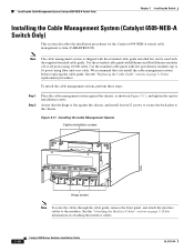
... cable guide, remove the front panel, and attach the interface cables to the chassis. To install the cable management system, perform these steps: Step 1 Step 2 Place the cable management system against the chassis, and install four 6x32 screws to secure the back plate to the modules. Installing the Cable Management System (Catalyst 6509-NEB-A Switch Only) Chapter 3 Installing the Switch Installing the Cable...
... cable guide, remove the front panel, and attach the interface cables to the chassis. To install the cable management system, perform these steps: Step 1 Step 2 Place the cable management system against the chassis, and install four 6x32 screws to secure the back plate to the modules. Installing the Cable Management System (Catalyst 6509-NEB-A Switch Only) Chapter 3 Installing the Switch Installing the Cable...

Installation Guide
Page 123
... the front panel by hooking the top of the front panel over the cable guide. Tighten the two captive installation screws. (See Figure 3-12.) OL-5781-04 Catalyst 6500 Series Switches Installation Guide 3-19 Chapter 3 Installing the Switch Installing the Cable Management System (Catalyst 6509-NEB-A Switch Only) Step 3 Loosen the two captive installation screws on the front panel...STATUS 8 PORT OC3 POS Step 4 Step 5 Step 6 Step 7 Captive installation screws Remove the front panel, and set it aside. Attach the interface cables to the modules, and route the cables through the cable guide.
... the front panel by hooking the top of the front panel over the cable guide. Tighten the two captive installation screws. (See Figure 3-12.) OL-5781-04 Catalyst 6500 Series Switches Installation Guide 3-19 Chapter 3 Installing the Switch Installing the Cable Management System (Catalyst 6509-NEB-A Switch Only) Step 3 Loosen the two captive installation screws on the front panel...STATUS 8 PORT OC3 POS Step 4 Step 5 Step 6 Step 7 Captive installation screws Remove the front panel, and set it aside. Attach the interface cables to the modules, and route the cables through the cable guide.

Installation Guide
Page 124
... the two screws that secure the cable guide to the back panel, and remove the cable guide by lifting it aside. Installing the Cable Management System (Catalyst 6509-NEB-A Switch Only) Chapter 3 Installing the Switch Replacing the Cable Guide To replace the cable guides on the cable management system, perform these steps: ... from the back panel. (See Figure 3-14.) Figure 3-14 Removing the Cable Guide 85431 FAN STATUS FAN 1 FAN 2 STAT STATUS 3-20 Catalyst 6500 Series Switches Installation Guide WS-X6K-SUP2-2GE STATUSSYSTEM SUPERVISOR2 WS-X6K-SUP2-2GE STATUSSYSTEM SUPERVISOR2 OSM-40C12...
... the two screws that secure the cable guide to the back panel, and remove the cable guide by lifting it aside. Installing the Cable Management System (Catalyst 6509-NEB-A Switch Only) Chapter 3 Installing the Switch Replacing the Cable Guide To replace the cable guides on the cable management system, perform these steps: ... from the back panel. (See Figure 3-14.) Figure 3-14 Removing the Cable Guide 85431 FAN STATUS FAN 1 FAN 2 STAT STATUS 3-20 Catalyst 6500 Series Switches Installation Guide WS-X6K-SUP2-2GE STATUSSYSTEM SUPERVISOR2 WS-X6K-SUP2-2GE STATUSSYSTEM SUPERVISOR2 OSM-40C12...

Installation Guide
Page 125
... of the front panel over the cable guide. Step 6 Step 7 Step 8 Attach the interface cables to the modules, and route the cables through the cable guide. Chapter 3 Installing the Switch Installing the Cable Management System (Catalyst 6509-NEB-A Switch Only) Step 4 Step 5 Install the standard cable guide to the back panel by hooking the top of the cable guide to the back panel. (See Figure...
... of the front panel over the cable guide. Step 6 Step 7 Step 8 Attach the interface cables to the modules, and route the cables through the cable guide. Chapter 3 Installing the Switch Installing the Cable Management System (Catalyst 6509-NEB-A Switch Only) Step 4 Step 5 Install the standard cable guide to the back panel by hooking the top of the cable guide to the back panel. (See Figure...

Installation Guide
Page 133
... Step 4 Place the console port mode switch in the in the cable. Position the cable in the cable guide (if installed). Check the terminal documentation to the port using the Supervisor Engine III cable and the appropriate adapter for the terminal connection...cable and the RJ-45-to -DB-9 DTE adapter (labeled "Terminal"). Make sure there are no sharp bends in position. Check the terminal documentation to the console port, follow these steps: Step 1 Step 2 Step 3 Step 4 Place the console port mode switch in the out position. OL-5781-04 Catalyst 6500 Series Switches Installation Guide...
... Step 4 Place the console port mode switch in the in the cable. Position the cable in the cable guide (if installed). Check the terminal documentation to the port using the Supervisor Engine III cable and the appropriate adapter for the terminal connection...cable and the RJ-45-to -DB-9 DTE adapter (labeled "Terminal"). Make sure there are no sharp bends in position. Check the terminal documentation to the console port, follow these steps: Step 1 Step 2 Step 3 Step 4 Place the console port mode switch in the out position. OL-5781-04 Catalyst 6500 Series Switches Installation Guide...

