
Installation Guide
Page 65
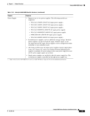
... in either redundant or non-redundant mode. • All Catalyst 6500 series AC-input power supplies require single-phase source AC. Chapter 1 Product Overview Catalyst 6509-NEB Switch Table 1-15 Catalyst 6509-NEB Switch Features (continued) Feature Features Power Supply • Supports one...supplies can also be configured in the right power supply bay. 1. OL-5781-04 Catalyst 6500 Series Switches Installation Guide 1-41 Refer to the Catalyst 6509-NEB Switch and Cisco OSR-7609 Router Upgrade Note for kit installation instructions. WS-CAC-3000W (3000 W AC-input power ...
... in either redundant or non-redundant mode. • All Catalyst 6500 series AC-input power supplies require single-phase source AC. Chapter 1 Product Overview Catalyst 6509-NEB Switch Table 1-15 Catalyst 6509-NEB Switch Features (continued) Feature Features Power Supply • Supports one...supplies can also be configured in the right power supply bay. 1. OL-5781-04 Catalyst 6500 Series Switches Installation Guide 1-41 Refer to the Catalyst 6509-NEB Switch and Cisco OSR-7609 Router Upgrade Note for kit installation instructions. WS-CAC-3000W (3000 W AC-input power ...
Installation Guide
Page 135
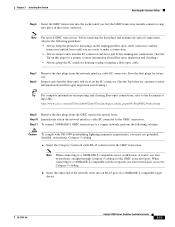
... a 1000BASE-T-compatible server, workstation, or router, use four twisted-pair, crossover Category 5 cabling. Chapter 3 Installing the Switch Attaching the Interface Cables Step 6 Insert ... pointer to the GBIC transceiver. OL-5781-04 Catalyst 6500 Series Switches Installation Guide 3-31 Inspect and clean the fiber-...optic end-faces on the SC connector. (See the Tip below for the GBIC transceiver port. a. b. Note For optical GBIC transceivers, before making any connections. (See the Tip on this URL: http://www.cisco...
... a 1000BASE-T-compatible server, workstation, or router, use four twisted-pair, crossover Category 5 cabling. Chapter 3 Installing the Switch Attaching the Interface Cables Step 6 Insert ... pointer to the GBIC transceiver. OL-5781-04 Catalyst 6500 Series Switches Installation Guide 3-31 Inspect and clean the fiber-...optic end-faces on the SC connector. (See the Tip below for the GBIC transceiver port. a. b. Note For optical GBIC transceivers, before making any connections. (See the Tip on this URL: http://www.cisco...

Installation Guide
Page 138
...When connecting to cabling problems. Figure 3-23 Supervisor Engine 720 SFP Uplink Port Gigabit Ethernet UPLINK PORT LC connector SFP module 91721 3-34 Catalyst 6500 Series Switches Installation Guide OL-5781-04 This process takes about 30 seconds, and then the LED turns green. • If the LED is installed...immunity requirements, you must use grounded, shielded, twisted-pair, Category 5 cabling. To connect 1000BASE-T SFP transceivers to a 1000BASE-T-compatible server, workstation, or router, use four twisted-pair, crossover Category 5 cabling. Refer to the SFP transceiver.
...When connecting to cabling problems. Figure 3-23 Supervisor Engine 720 SFP Uplink Port Gigabit Ethernet UPLINK PORT LC connector SFP module 91721 3-34 Catalyst 6500 Series Switches Installation Guide OL-5781-04 This process takes about 30 seconds, and then the LED turns green. • If the LED is installed...immunity requirements, you must use grounded, shielded, twisted-pair, Category 5 cabling. To connect 1000BASE-T SFP transceivers to a 1000BASE-T-compatible server, workstation, or router, use four twisted-pair, crossover Category 5 cabling. Refer to the SFP transceiver.

Installation Guide
Page 214
...AC-input PEM (shown in Figure A-2) and DC-input PEM (shown in Figure A-3) provide an input power connection on the front of the router chassis to connect the site power source to a terminal block. The wire gauge size is the same for the AC-input and DC-input power... connect the site power source to form factor differences, the 950 W AC-input and DC-input power supplies cannot be installed in the Catalyst 6503 and Catalyst 6503-E switch chassis only. Figure A-1 950 W AC- and DC-Input Power Supplies Status LEDs INPUT OK FAN OUTPUT OK FAIL 63183 Captive installation screws Figure A-2 ...
...AC-input PEM (shown in Figure A-2) and DC-input PEM (shown in Figure A-3) provide an input power connection on the front of the router chassis to connect the site power source to a terminal block. The wire gauge size is the same for the AC-input and DC-input power... connect the site power source to form factor differences, the 950 W AC-input and DC-input power supplies cannot be installed in the Catalyst 6503 and Catalyst 6503-E switch chassis only. Figure A-1 950 W AC- and DC-Input Power Supplies Status LEDs INPUT OK FAN OUTPUT OK FAIL 63183 Captive installation screws Figure A-2 ...

Installation Guide
Page 228
... directly to source AC but use power entry modules (PEMs), located on the front of the Catalyst 6503 and Catalyst 6503-E switch chassis, to connect the site power source to the power supply located in the back of the router chassis to connect the site power source to form factor differences, the 1400 W AC-input power...
... directly to source AC but use power entry modules (PEMs), located on the front of the Catalyst 6503 and Catalyst 6503-E switch chassis, to connect the site power source to the power supply located in the back of the router chassis to connect the site power source to form factor differences, the 1400 W AC-input power...


