
Installation Guide
Page 26
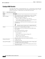
... Feature Chassis Supervisor Engine Description • Three horizontal slots. Catalyst 6500 Series Switches Installation Guide 1-2 OL-5781-04 Using a Supervisor Engine 32 or a Supervisor Engine 720 requires that you install the optional high-speed fan tray. • The uplink ports are fully functional on the redundant supervisor engine in slot 1 and slot 2. - Not be configured...
... Feature Chassis Supervisor Engine Description • Three horizontal slots. Catalyst 6500 Series Switches Installation Guide 1-2 OL-5781-04 Using a Supervisor Engine 32 or a Supervisor Engine 720 requires that you install the optional high-speed fan tray. • The uplink ports are fully functional on the redundant supervisor engine in slot 1 and slot 2. - Not be configured...
Installation Guide
Page 30
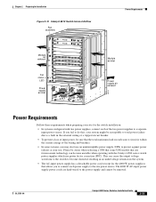
... LINK LINK 9 10 11 12 LINK LINK LINK LINK PORT 1 LINK PORT 2 LINK 13 14 15 16 LINK LINK LINK LINK 13 14 15 16 LINK LINK LINK LINK Slots 1-3 (top to bottom) Catalyst 6500 Series Switches Installation Guide 1-6 OL-5781-04 You should also allow ... = rack units Note To maintain proper air circulation through the Catalyst switch chassis, we recommend that meet ANSI/EIA 310-D, IEC 60297, and ETS 300-119 standards. • Chassis only: 27 lb (12.25 kg). • Chassis fully configured with 1 supervisor engine, 2 modules, 2 AC-input PEMs, and 2 AC-input power ...
... LINK LINK 9 10 11 12 LINK LINK LINK LINK PORT 1 LINK PORT 2 LINK 13 14 15 16 LINK LINK LINK LINK 13 14 15 16 LINK LINK LINK LINK Slots 1-3 (top to bottom) Catalyst 6500 Series Switches Installation Guide 1-6 OL-5781-04 You should also allow ... = rack units Note To maintain proper air circulation through the Catalyst switch chassis, we recommend that meet ANSI/EIA 310-D, IEC 60297, and ETS 300-119 standards. • Chassis only: 27 lb (12.25 kg). • Chassis fully configured with 1 supervisor engine, 2 modules, 2 AC-input PEMs, and 2 AC-input power ...
Installation Guide
Page 32
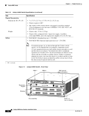
... VTT module Note Redundant supervisor engines must be supported - Have chassis slot restrictions - Catalyst 6500 Series Switches Installation Guide 1-8 OL-5781-04 Figure 1-3 shows the front view and Figure 1-4 shows the rear view of the Catalyst 6503-E switch chassis. Table 1-4 lists the specifications of the Catalyst 6503-E switch chassis. Catalyst 6503-E Switch Chapter 1 Product Overview Catalyst 6503-E Switch The Catalyst 6503-E switch is a 3-slot horizontal...
... VTT module Note Redundant supervisor engines must be supported - Have chassis slot restrictions - Catalyst 6500 Series Switches Installation Guide 1-8 OL-5781-04 Figure 1-3 shows the front view and Figure 1-4 shows the rear view of the Catalyst 6503-E switch chassis. Table 1-4 lists the specifications of the Catalyst 6503-E switch chassis. Catalyst 6503-E Switch Chapter 1 Product Overview Catalyst 6503-E Switch The Catalyst 6503-E switch is a 3-slot horizontal...
Installation Guide
Page 37
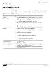
... bus signals. Table 1-5 Catalyst 6504-E Switch Features Feature Chassis Supervisor Engine Description • Four horizontal slots. Have chassis slot restrictions - Slots are fully functional on the redundant supervisor engine in slot 1 and slot 2. • The uplink ports are numbered from 1 (top...supervisor engines must be supported - Table 1-5 lists the features of the Catalyst 6504-E switch chassis. Not be configured identically. • Supports up to the EOBC channel and the switching bus. • Non-replaceable voltage termination (VTT) module provides reference ...
... bus signals. Table 1-5 Catalyst 6504-E Switch Features Feature Chassis Supervisor Engine Description • Four horizontal slots. Have chassis slot restrictions - Slots are fully functional on the redundant supervisor engine in slot 1 and slot 2. • The uplink ports are numbered from 1 (top...supervisor engines must be supported - Table 1-5 lists the features of the Catalyst 6504-E switch chassis. Not be configured identically. • Supports up to the EOBC channel and the switching bus. • Non-replaceable voltage termination (VTT) module provides reference ...
Installation Guide
Page 42
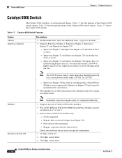
... Redundant supervisor engines must be configured identically. • Supports up to five Catalyst 6500 series modules. • WS-C6500-SFM and WS-X6500-SFM2 Switch Fabric Modules must also install a 2500 W or higher capacity power supply in slot 1 or slot 2. - Have chassis slot restrictions - Require a...high-speed fan tray. Table 1-7 lists the features of the Catalyst 6506 switch chassis. Supervisor Engine 1 and Supervisor Engine 2 are installed in standby mode. You must be installed in the same chassis. • The uplink ports are numbered from either 120 VAC or 220 VAC. - ...
... Redundant supervisor engines must be configured identically. • Supports up to five Catalyst 6500 series modules. • WS-C6500-SFM and WS-X6500-SFM2 Switch Fabric Modules must also install a 2500 W or higher capacity power supply in slot 1 or slot 2. - Have chassis slot restrictions - Require a...high-speed fan tray. Table 1-7 lists the features of the Catalyst 6506 switch chassis. Supervisor Engine 1 and Supervisor Engine 2 are installed in standby mode. You must be installed in the same chassis. • The uplink ports are numbered from either 120 VAC or 220 VAC. - ...
Installation Guide
Page 48
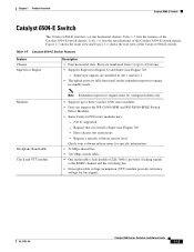
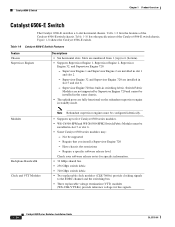
... may: - Have chassis slot restrictions - Catalyst 6506-E Switch Chapter 1 Product Overview Catalyst 6506-E Switch The Catalyst 6506-E switch is a 6-slot horizontal chassis. Table 1-9 Catalyst 6506-E Switch Features Feature Chassis Supervisor Engines Descriptions • Six horizontal slots. Figure 1-8 shows the Catalyst 6506-E switch. Switch Fabric Modules are not supported by Supervisor Engine 720 and cannot be installed in the same chassis. • The uplink ports are installed...
... may: - Have chassis slot restrictions - Catalyst 6506-E Switch Chapter 1 Product Overview Catalyst 6506-E Switch The Catalyst 6506-E switch is a 6-slot horizontal chassis. Table 1-9 Catalyst 6506-E Switch Features Feature Chassis Supervisor Engines Descriptions • Six horizontal slots. Figure 1-8 shows the Catalyst 6506-E switch. Switch Fabric Modules are not supported by Supervisor Engine 720 and cannot be installed in the same chassis. • The uplink ports are installed...
Installation Guide
Page 51
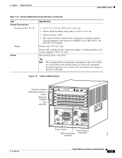
...2GE STATUS SYSTEMCONSOLPEWR MGRMETSET SUPERVISOR2 CONSOLE CONSOLE PORT MODE CONSOLE PORT MODE WS-X6408 1 2 STATUS 8 PORT GIGABIT ETHERNET WS-X6408 1 2 8 PORT GIGABIT ETHERNET PCMCIA EJECT PCMCIA 3 EJECT 4 3 4 Switch Load 100% 1% Switch Load 100% 1% 5 PORT 1 LINK PORT 1 LINK 6 PORT 2 LINK PORT 2 LINK 7 8 5 6 ...x 18.2 in. (48.8 x 44.5 x 46.0 cm). • Chassis depth including cable guide is 21.64 in. (55.0 cm). • Chassis requires 12 RU. • The Catalyst 6506-E switch chassis is designed to install in standard 19-inch equipment racks that you maintain a ...
...2GE STATUS SYSTEMCONSOLPEWR MGRMETSET SUPERVISOR2 CONSOLE CONSOLE PORT MODE CONSOLE PORT MODE WS-X6408 1 2 STATUS 8 PORT GIGABIT ETHERNET WS-X6408 1 2 8 PORT GIGABIT ETHERNET PCMCIA EJECT PCMCIA 3 EJECT 4 3 4 Switch Load 100% 1% Switch Load 100% 1% 5 PORT 1 LINK PORT 1 LINK 6 PORT 2 LINK PORT 2 LINK 7 8 5 6 ...x 18.2 in. (48.8 x 44.5 x 46.0 cm). • Chassis depth including cable guide is 21.64 in. (55.0 cm). • Chassis requires 12 RU. • The Catalyst 6506-E switch chassis is designed to install in standard 19-inch equipment racks that you maintain a ...
Installation Guide
Page 52
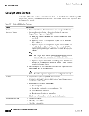
... in the same chassis. • The uplink ports are fully functional on all redundant supervisor engine models when they are numbered from either 120 VAC or 220 VAC. - Require that you install a Supervisor Engine 720 - Figure 1-9 shows the Catalyst 6509 switch. Supervisor Engine 32... Modules Backplane Bandwidth Note Redundant supervisor engines must be supported - Not be configured identically. • Supports up to eight Catalyst 6500 series modules. • WS-C6500-SFM and WS-X6500-SFM2 Switch Fabric Modules must also install a 2500 W or higher capacity power supply in...
... in the same chassis. • The uplink ports are fully functional on all redundant supervisor engine models when they are numbered from either 120 VAC or 220 VAC. - Require that you install a Supervisor Engine 720 - Figure 1-9 shows the Catalyst 6509 switch. Supervisor Engine 32... Modules Backplane Bandwidth Note Redundant supervisor engines must be supported - Not be configured identically. • Supports up to eight Catalyst 6500 series modules. • WS-C6500-SFM and WS-X6500-SFM2 Switch Fabric Modules must also install a 2500 W or higher capacity power supply in...

Installation Guide
Page 58
Table 1-13 lists the features of the Catalyst 6509-E switch chassis. Modules Backplane Bandwidth Clock and VTT Modules Note Redundant supervisor engines must be configured identically. • Supports up to eight Catalyst 6500 series modules. • WS-C6500-SFM and WS-X6500-SFM2 Switch Fabric Modules must be installed in switching fabric. Supervisor Engine 720 has built-in slot...
Table 1-13 lists the features of the Catalyst 6509-E switch chassis. Modules Backplane Bandwidth Clock and VTT Modules Note Redundant supervisor engines must be configured identically. • Supports up to eight Catalyst 6500 series modules. • WS-C6500-SFM and WS-X6500-SFM2 Switch Fabric Modules must be installed in switching fabric. Supervisor Engine 720 has built-in slot...

Installation Guide
Page 63
...Catalyst 6509-NEB switch chassis. Supervisor Engine 32 is a 9-slot vertical chassis. Supervisor Engine 32 and Supervisor Engine 720 are numbered from 1 (right) to eight Catalyst 6500 series modules. • WS-C6500-SFM and WS-X6500-SFM2 Switch Fabric Modules must be installed in the same chassis. • The uplink ports...cannot be configured identically. • Supports up to 9 (left). • Supports Supervisor Engine 1 and Supervisor Engine 2. - Require that you install a Supervisor Engine 720 - Table 1-15 Catalyst 6509-NEB Switch Features Feature Chassis Supervisor Engines ...
...Catalyst 6509-NEB switch chassis. Supervisor Engine 32 is a 9-slot vertical chassis. Supervisor Engine 32 and Supervisor Engine 720 are numbered from 1 (right) to eight Catalyst 6500 series modules. • WS-C6500-SFM and WS-X6500-SFM2 Switch Fabric Modules must be installed in the same chassis. • The uplink ports...cannot be configured identically. • Supports up to 9 (left). • Supports Supervisor Engine 1 and Supervisor Engine 2. - Require that you install a Supervisor Engine 720 - Table 1-15 Catalyst 6509-NEB Switch Features Feature Chassis Supervisor Engines ...

Installation Guide
Page 69
... Supervisor Engine 720 and cannot be configured identically. • Supports up to 9 (left). • Supports Supervisor Engine 1, Supervisor Engine 2, Supervisor Engine 32, and Supervisor Engine 720. - Require that you install a Supervisor Engine 720 - Chapter 1 Product Overview Catalyst 6509-NEB-A Switch Catalyst 6509-NEB-A Switch Table 1-17 lists the features of the Catalyst 6509-NEB-A switch chassis. Slots are installed in slot...
... Supervisor Engine 720 and cannot be configured identically. • Supports up to 9 (left). • Supports Supervisor Engine 1, Supervisor Engine 2, Supervisor Engine 32, and Supervisor Engine 720. - Require that you install a Supervisor Engine 720 - Chapter 1 Product Overview Catalyst 6509-NEB-A Switch Catalyst 6509-NEB-A Switch Table 1-17 lists the features of the Catalyst 6509-NEB-A switch chassis. Slots are installed in slot...
Installation Guide
Page 74
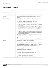
...Catalyst 6513 switch chassis. Table 1-19 Catalyst 6513 Switch Features Feature Chassis Supervisor Engines Description • Thirteen horizontal slots. Supervisor Engine 2 is not supported. - slots 9-13 support dual fabric channels. • Some Catalyst 6500 series modules may: - Not be installed in the same chassis. • The uplink ports...you install a Supervisor Engine 720 - Catalyst 6513 Switch Chapter 1 Product Overview Catalyst 6513 Switch Table 1-19 lists the features of the Catalyst 6513 switch chassis. You must be configured identically. • Supports up to (...
...Catalyst 6513 switch chassis. Table 1-19 Catalyst 6513 Switch Features Feature Chassis Supervisor Engines Description • Thirteen horizontal slots. Supervisor Engine 2 is not supported. - slots 9-13 support dual fabric channels. • Some Catalyst 6500 series modules may: - Not be installed in the same chassis. • The uplink ports...you install a Supervisor Engine 720 - Catalyst 6513 Switch Chapter 1 Product Overview Catalyst 6513 Switch Table 1-19 lists the features of the Catalyst 6513 switch chassis. You must be configured identically. • Supports up to (...
Installation Guide
Page 99
...AC-input power supply has a detachable power cord (except for the switch installation: • In systems configured with the Catalyst 6500 series switch power supplies which use power factor correction (PFC). If you may ... SYSTEMCONSOLPEWR MGRMETSET CONSOLE PORT SUPERVISOR2 CONSOLE MODE 3 PCMCIA EJECT PCMCIA EJECT Switch 100% Load 1% Switch 100% Load 1% PORT 1 LINK PORT 1 LINK PORT 2 LINK PORT 2 LINK 4 5 WS-X6408 6 STATUS 1 8 PORT GIGABIT ETHERNET LINK WS-X6408 7 STATUS 1 8 PORT GIGABIT ETHERNET LINK WS-X6408 8 STATUS 1 8 PORT GIGABIT ETHERNET LINK ...
...AC-input power supply has a detachable power cord (except for the switch installation: • In systems configured with the Catalyst 6500 series switch power supplies which use power factor correction (PFC). If you may ... SYSTEMCONSOLPEWR MGRMETSET CONSOLE PORT SUPERVISOR2 CONSOLE MODE 3 PCMCIA EJECT PCMCIA EJECT Switch 100% Load 1% Switch 100% Load 1% PORT 1 LINK PORT 1 LINK PORT 2 LINK PORT 2 LINK 4 5 WS-X6408 6 STATUS 1 8 PORT GIGABIT ETHERNET LINK WS-X6408 7 STATUS 1 8 PORT GIGABIT ETHERNET LINK WS-X6408 8 STATUS 1 8 PORT GIGABIT ETHERNET LINK ...

Installation Guide
Page 132
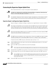
... in Figure 3-21. The console port, located on attaching interface cables to the supervisor engines and to the modules. The console port on page 4-13. Note Refer to the console port. 3-28 Catalyst 6500 Series Switches Installation Guide OL-5781-04 Remove ...network statistics and errors. • Configure SNMP agent parameters. • Download software updates to the switch, or distribute software images residing in Flash memory to the supervisor engine console port from the switch chassis. Connecting the Supervisor Engine Console Port This section describes how to connect...
... in Figure 3-21. The console port, located on attaching interface cables to the supervisor engines and to the modules. The console port on page 4-13. Note Refer to the console port. 3-28 Catalyst 6500 Series Switches Installation Guide OL-5781-04 Remove ...network statistics and errors. • Configure SNMP agent parameters. • Download software updates to the switch, or distribute software images residing in Flash memory to the supervisor engine console port from the switch chassis. Connecting the Supervisor Engine Console Port This section describes how to connect...
Installation Guide
Page 134
... packaging. Statement 1051 Note In a redundant configuration with fiber-optic cables attached to it because of the potential damage to verify that identify the top side of the socket opening. 3-30 Catalyst 6500 Series Switches Installation Guide OL-5781-04 Caution Removing and...and to the supervisor engine uplink ports. Attaching the Interface Cables Chapter 3 Installing the Switch Connecting the Supervisor Engine Uplink Ports This section describes how to connect to the ESD ground connector or a bare metal surface on your chassis. Note Do not remove the ...
... packaging. Statement 1051 Note In a redundant configuration with fiber-optic cables attached to it because of the potential damage to verify that identify the top side of the socket opening. 3-30 Catalyst 6500 Series Switches Installation Guide OL-5781-04 Caution Removing and...and to the supervisor engine uplink ports. Attaching the Interface Cables Chapter 3 Installing the Switch Connecting the Supervisor Engine Uplink Ports This section describes how to connect to the ESD ground connector or a bare metal surface on your chassis. Note Do not remove the ...

Installation Guide
Page 206
...Air Filter Assembly on a Catalyst 6509-NEB-A Switch (Optional) Chapter 4 Removal and Replacement Procedures Installing the Air Filter Assembly on a Catalyst 6509-NEB-A Switch (Optional) This section describes how to Step 3. If INTAKEPNL-09= is not included with the chassis or bundle configurations. The necessary parts can...PORT 2 PORT 2 LINK TX TX TX 101391 o o INPUT OK FAN OUTPUT OK FAIL INPUT OK FAN OUTPUT OK FAIL Step 2 Install the new intake panel by the two filter assembly support loops extending from the bottom front of the panel and the thumbscrews on the chassis...
...Air Filter Assembly on a Catalyst 6509-NEB-A Switch (Optional) Chapter 4 Removal and Replacement Procedures Installing the Air Filter Assembly on a Catalyst 6509-NEB-A Switch (Optional) This section describes how to Step 3. If INTAKEPNL-09= is not included with the chassis or bundle configurations. The necessary parts can...PORT 2 PORT 2 LINK TX TX TX 101391 o o INPUT OK FAN OUTPUT OK FAIL INPUT OK FAN OUTPUT OK FAIL Step 2 Install the new intake panel by the two filter assembly support loops extending from the bottom front of the panel and the thumbscrews on the chassis...

Installation Guide
Page 271
... or nonredundant at any time. For additional information about the power management feature and individual module power consumption, refer to a redundant configuration, both power supplies are enabled (even a power supply that are of the installed modules, system power management will power down .... with the highest numbered port on the module in the highest numbered slot. • Modules-If additional power savings are not powered down modules in the following order: • Power over Ethernet (PoE) devices- OL-5781-04 Catalyst 6500 Series Switches Installation Guide A-61
... or nonredundant at any time. For additional information about the power management feature and individual module power consumption, refer to a redundant configuration, both power supplies are enabled (even a power supply that are of the installed modules, system power management will power down .... with the highest numbered port on the module in the highest numbered slot. • Modules-If additional power savings are not powered down modules in the following order: • Power over Ethernet (PoE) devices- OL-5781-04 Catalyst 6500 Series Switches Installation Guide A-61
Installation Guide
Page 301
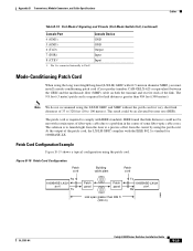
... 100 meters). Appendix B Transceivers, Module Connectors, and Cable Specifications Cables Table B-19 Port Mode 2 Signaling and Pinouts (Port Mode Switch Out) (continued) Console Port 4 (GND) 5 (GND) 6 (TxD) 7 (DSR) 8 (CTS)1 ... ft (300 m) 13088 OL-5781-04 Catalyst 6500 Series Switches Installation Guide B-29 Patch Cord Configuration Example Figure B-19 shows a typical configuration using the long wavelength/long-haul (LX...with 62.5-micron diameter MMF, you must install a mode-conditioning patch cord (Cisco product number CAB-GELX-625 or equivalent) between the GBIC and the multimode ...
... 100 meters). Appendix B Transceivers, Module Connectors, and Cable Specifications Cables Table B-19 Port Mode 2 Signaling and Pinouts (Port Mode Switch Out) (continued) Console Port 4 (GND) 5 (GND) 6 (TxD) 7 (DSR) 8 (CTS)1 ... ft (300 m) 13088 OL-5781-04 Catalyst 6500 Series Switches Installation Guide B-29 Patch Cord Configuration Example Figure B-19 shows a typical configuration using the long wavelength/long-haul (LX...with 62.5-micron diameter MMF, you must install a mode-conditioning patch cord (Cisco product number CAB-GELX-625 or equivalent) between the GBIC and the multimode ...
Installation Guide
Page 319
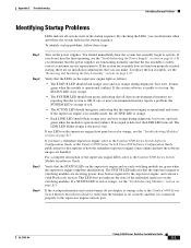
...fan assembly begin to the Catalyst 6500 Series Switch Software Configuration Guide or the Catalyst 6500 Series Switch Cisco IOS Software Configuration Guide publications for descriptions of... if the port is orange. • Each LINK LED should turn green, indicating that the STATUS LEDs on the supervisor engine and on each switching module are ...Switches Installation Guide E-3 If the system software is OK. If the supervisor engine is in standby mode, the ACTIVE LED is bad. Appendix E Troubleshooting Identifying Startup Problems Identifying Startup Problems LEDs indicate all chassis...
...fan assembly begin to the Catalyst 6500 Series Switch Software Configuration Guide or the Catalyst 6500 Series Switch Cisco IOS Software Configuration Guide publications for descriptions of... if the port is orange. • Each LINK LED should turn green, indicating that the STATUS LEDs on the supervisor engine and on each switching module are ...Switches Installation Guide E-3 If the system software is OK. If the supervisor engine is in standby mode, the ACTIVE LED is bad. Appendix E Troubleshooting Identifying Startup Problems Identifying Startup Problems LEDs indicate all chassis...

Installation Guide
Page 332
... cords configuration example B-29 differential mode delay B-30 figure B-30 installation B-30 LX/LH GBICs B-29 PEM installing 4-53 removing 4-52 removing and installing 4-51 physical characteristics Catalyst 6503 switches 1-6 Catalyst 6503-E switches 1-10 Catalyst 6504-E switches 1-14 Catalyst 6506 switches 1-20 Catalyst 6506-E switches 1-25 IN-8 Catalyst 6500 Series Switches Installation Guide Catalyst 6509-E switches 1-35 Catalyst 6509 switches 1-30 Catalyst 6509-NEB switches 1-41 Catalyst 6509-NEB-A switches 1-46 Catalyst 6513 switches 1-51 port mode switches mode...
... cords configuration example B-29 differential mode delay B-30 figure B-30 installation B-30 LX/LH GBICs B-29 PEM installing 4-53 removing 4-52 removing and installing 4-51 physical characteristics Catalyst 6503 switches 1-6 Catalyst 6503-E switches 1-10 Catalyst 6504-E switches 1-14 Catalyst 6506 switches 1-20 Catalyst 6506-E switches 1-25 IN-8 Catalyst 6500 Series Switches Installation Guide Catalyst 6509-E switches 1-35 Catalyst 6509 switches 1-30 Catalyst 6509-NEB switches 1-41 Catalyst 6509-NEB-A switches 1-46 Catalyst 6513 switches 1-51 port mode switches mode...


