
Installation Guide
Page 6
... Cable Guides on the Catalyst 6506 and Catalyst 6506-E Switches 3-11 Installing the L Brackets and Cable Guides on the Catalyst 6509 and Catalyst 6509-E Switches 3-13 Installing the L Brackets and Cable Guides on the Catalyst 6509-NEB Switch 3-15 Installing the L Brackets on the Catalyst 6509-NEB-A Switch 3-17 Installing the Switch Chassis in the Rack 3-18 Installing the Stabilizer Bracket Kit 3-20 Required Tools 3-20 Installing...
... Cable Guides on the Catalyst 6506 and Catalyst 6506-E Switches 3-11 Installing the L Brackets and Cable Guides on the Catalyst 6509 and Catalyst 6509-E Switches 3-13 Installing the L Brackets and Cable Guides on the Catalyst 6509-NEB Switch 3-15 Installing the L Brackets on the Catalyst 6509-NEB-A Switch 3-17 Installing the Switch Chassis in the Rack 3-18 Installing the Stabilizer Bracket Kit 3-20 Required Tools 3-20 Installing...
Installation Guide
Page 7
Contents 4 C H A P T E R Installing the Cable Management System (Catalyst 6509-NEB-A Switch Only) 3-23 Replacing the Cable Guide 3-25 Establishing the System Ground 3-27 Required Tools and Parts 3-28 Connecting the System Ground 3-29 Installing the Power Supplies in the Switch Chassis 3-34 Attaching the Interface Cables 3-34 Connecting the Supervisor Engine Console Port 3-34 Connecting the Supervisor Engine Uplink...
Contents 4 C H A P T E R Installing the Cable Management System (Catalyst 6509-NEB-A Switch Only) 3-23 Replacing the Cable Guide 3-25 Establishing the System Ground 3-27 Required Tools and Parts 3-28 Connecting the System Ground 3-29 Installing the Power Supplies in the Switch Chassis 3-34 Attaching the Interface Cables 3-34 Connecting the Supervisor Engine Console Port 3-34 Connecting the Supervisor Engine Uplink...
Installation Guide
Page 28
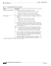
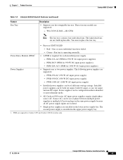
...-input. PWR-1400-AC (1400 W AC-input power supply). • Installed power supplies can be of phase between multiple power supplies or multiple AC-power plugs on the same power supply because all AC power supply inputs are isolated. • Single power supplies are required for each installed power supply. - The second power supply is required for Catalyst 6503 and Catalyst 6503-E switches only.
...-input. PWR-1400-AC (1400 W AC-input power supply). • Installed power supplies can be of phase between multiple power supplies or multiple AC-power plugs on the same power supply because all AC power supply inputs are isolated. • Single power supplies are required for each installed power supply. - The second power supply is required for Catalyst 6503 and Catalyst 6503-E switches only.
Installation Guide
Page 30
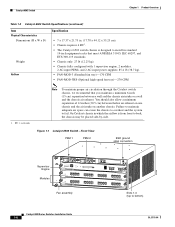
...the Catalyst switch chassis, we recommend that meet ANSI/EIA 310-D, IEC 60297, and ETS 300-119 standards. • Chassis only: 27 lb (12.25 kg). • Chassis fully configured with 1 supervisor engine, 2 modules, 2 AC-input PEMs, and 2 AC-input power supplies:.... Catalyst 6503 Switch Chapter 1 Product Overview Table 1-2 Catalyst 6503 Switch Specifications (continued) Item Physical Characteristics Dimensions (H x W x D) Weight Airflow Specification • 7 x 17.37 x 21.75 in. (17.78 x 44.12 x 55.25 cm). • Chassis requires 4 RU1. • The Catalyst 6503 switch chassis is...
...the Catalyst switch chassis, we recommend that meet ANSI/EIA 310-D, IEC 60297, and ETS 300-119 standards. • Chassis only: 27 lb (12.25 kg). • Chassis fully configured with 1 supervisor engine, 2 modules, 2 AC-input PEMs, and 2 AC-input power supplies:.... Catalyst 6503 Switch Chapter 1 Product Overview Table 1-2 Catalyst 6503 Switch Specifications (continued) Item Physical Characteristics Dimensions (H x W x D) Weight Airflow Specification • 7 x 17.37 x 21.75 in. (17.78 x 44.12 x 55.25 cm). • Chassis requires 4 RU1. • The Catalyst 6503 switch chassis is...
Installation Guide
Page 33
...+ (PEM for 950 W DC-input power supplies). - The following power supplies are supported: - The second power supply is required for each installed power supply. - Installed power supplies can be both AC-input, both DC-input, or one AC-input and one hot-swappable fan tray. Chapter 1 Product Overview Catalyst 6503-E Switch Table 1-3 Catalyst 6503-E Switch Features (continued) Feature Fan Tray...
...+ (PEM for 950 W DC-input power supplies). - The following power supplies are supported: - The second power supply is required for each installed power supply. - Installed power supplies can be both AC-input, both DC-input, or one AC-input and one hot-swappable fan tray. Chapter 1 Product Overview Catalyst 6503-E Switch Table 1-3 Catalyst 6503-E Switch Features (continued) Feature Fan Tray...

Installation Guide
Page 81
... Requirements, page 2-2 • Power Requirements, page 2-19 • Cabling Requirements, page 2-21 • Site Preparation Checklist, page 2-22 For detailed information about module cabling requirements, refer to the switch and control of the environment. Equipment placed too close together or inadequately ventilated can make chassis panels inaccessible and difficult to the switch chassis listed in Chapter 1. OL-5781-04 Catalyst...
... Requirements, page 2-2 • Power Requirements, page 2-19 • Cabling Requirements, page 2-21 • Site Preparation Checklist, page 2-22 For detailed information about module cabling requirements, refer to the switch and control of the environment. Equipment placed too close together or inadequately ventilated can make chassis panels inaccessible and difficult to the switch chassis listed in Chapter 1. OL-5781-04 Catalyst...
Installation Guide
Page 99
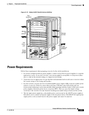
...technology can become unstable when operating with two power supplies, connect each power supply to the site power source. OL-5781-04 Catalyst 6500 Series Switches Installation Guide 2-19 Chapter 2 Preparing for Installation Figure 2-10 Catalyst 6513 Switch Internal Airflow Fan assembly Module air exhaust ...23 LINK 24 LINK Power supply air inlet o o INPUT OK FAN OUTPUT OK FAIL INPUT OK FAN OUTPUT OK FAIL 48122 Power Requirements Module air inlet Power supply air exhaust Power Requirements Follow these requirements when preparing your site for the 4000 W power supplies) that the...
...technology can become unstable when operating with two power supplies, connect each power supply to the site power source. OL-5781-04 Catalyst 6500 Series Switches Installation Guide 2-19 Chapter 2 Preparing for Installation Figure 2-10 Catalyst 6513 Switch Internal Airflow Fan assembly Module air exhaust ...23 LINK 24 LINK Power supply air inlet o o INPUT OK FAN OUTPUT OK FAIL INPUT OK FAN OUTPUT OK FAIL 48122 Power Requirements Module air inlet Power supply air exhaust Power Requirements Follow these requirements when preparing your site for the 4000 W power supplies) that the...

Installation Guide
Page 100
... service equipment. 2-20 Catalyst 6500 Series Switches Installation Guide OL-5781-04 Power Requirements Chapter 2 Preparing for connecting the Catalyst 6500 series switch AC power supplies to 2900 W. • For International: - The 1300 W, 1400 W, 2500 W, 2700 W, and 3000 W power supplies require a 20 A circuit. - The wire gauge size is limited to the site power source: • Each chassis power supply should be easily...
... service equipment. 2-20 Catalyst 6500 Series Switches Installation Guide OL-5781-04 Power Requirements Chapter 2 Preparing for connecting the Catalyst 6500 series switch AC power supplies to 2900 W. • For International: - The 1300 W, 1400 W, 2500 W, 2700 W, and 3000 W power supplies require a 20 A circuit. - The wire gauge size is limited to the site power source: • Each chassis power supply should be easily...

Installation Guide
Page 267
... in . (3.65 m) Hardwired to power supply 113366 Power Supply Redundancy Catalyst 6500 series switching modules have different power requirements. Depending upon the wattage of changing the power supply configurations are summarized in the chassis. Note For proper load-sharing operation in a redundant power supply configuration, you must install two modules in Table A-21. Appendix A Power Supply Specifications Figure A-45 WS...
... in . (3.65 m) Hardwired to power supply 113366 Power Supply Redundancy Catalyst 6500 series switching modules have different power requirements. Depending upon the wattage of changing the power supply configurations are summarized in the chassis. Note For proper load-sharing operation in a redundant power supply configuration, you must install two modules in Table A-21. Appendix A Power Supply Specifications Figure A-45 WS...

Installation Guide
Page 307
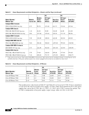
...the outlet to the system). Table D-1 Power Requirements and Heat Dissipation-Chassis and Fan Trays Model Number/ Module Type Catalyst 6503 chassis FAN-MOD-3 fan tray FAN-MOD-3HS fan tray Catalyst 6503-E chassis WS-C6503-E-FAN fan tray Catalyst 6504-E chassis FAN-MOD-4HS fan tray Catalyst 6506 chassis WS-C6K-6SLOT-FAN fan tray WS-C6K...00 113.00 Heat Diss. (BTU/HR) 156.00 574.49 264.11 275.68 136.88 386.00 OL-5781-04 Catalyst 6500 Series Switches Installation Guide D-1 Typical numbers are approximately 30 percent below the numbers listed in the following tables is the efficiency of the...
...the outlet to the system). Table D-1 Power Requirements and Heat Dissipation-Chassis and Fan Trays Model Number/ Module Type Catalyst 6503 chassis FAN-MOD-3 fan tray FAN-MOD-3HS fan tray Catalyst 6503-E chassis WS-C6503-E-FAN fan tray Catalyst 6504-E chassis FAN-MOD-4HS fan tray Catalyst 6506 chassis WS-C6K-6SLOT-FAN fan tray WS-C6K...00 113.00 Heat Diss. (BTU/HR) 156.00 574.49 264.11 275.68 136.88 386.00 OL-5781-04 Catalyst 6500 Series Switches Installation Guide D-1 Typical numbers are approximately 30 percent below the numbers listed in the following tables is the efficiency of the...
Installation Guide
Page 308
... installed in the chassis from the power supply's 42 VDC output. The Catalyst 6509-NEB-A switch chassis ships with two fan trays are based on 42 VDC. Power is independent of the power supply's input voltage, either 110 VAC or 220 VAC. Table D-2 Power Requirements and Heat Dissipation-IP Phones Model Number/ Module Type Cisco IP Phone 7960 Cisco IP Phone 7940...
... installed in the chassis from the power supply's 42 VDC output. The Catalyst 6509-NEB-A switch chassis ships with two fan trays are based on 42 VDC. Power is independent of the power supply's input voltage, either 110 VAC or 220 VAC. Table D-2 Power Requirements and Heat Dissipation-IP Phones Model Number/ Module Type Cisco IP Phone 7960 Cisco IP Phone 7940...
Installation Guide
Page 309
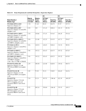
Appendix D Chassis and Module Power and Heat Values Table D-3 Power Requirements and Heat Dissipation-Supervisor Engines Model Number/ Module Type Module Module Current (A) Power @ 42 VDC (Watts) WS-X6K-SUP1A-2GE Supervisor Engine 1A 1.70 71.40 WS-X6K-SUP1A...72 Supervisor Engine 720 with PFC3B daughter card and integrated MSFC3 and switch fabric 282.24 AC AC-Input Power (Watts) 89.25 Heat Diss. (BTU/HR) 304.79 DC DC-Input Power (Watts) 95.97 131.25 448.22 141.13 173.25....91 667.03 667.03 460.75 364.36 1445.87 1295.5 OL-5781-04 Catalyst 6500 Series Switches Installation Guide D-3
Appendix D Chassis and Module Power and Heat Values Table D-3 Power Requirements and Heat Dissipation-Supervisor Engines Model Number/ Module Type Module Module Current (A) Power @ 42 VDC (Watts) WS-X6K-SUP1A-2GE Supervisor Engine 1A 1.70 71.40 WS-X6K-SUP1A...72 Supervisor Engine 720 with PFC3B daughter card and integrated MSFC3 and switch fabric 282.24 AC AC-Input Power (Watts) 89.25 Heat Diss. (BTU/HR) 304.79 DC DC-Input Power (Watts) 95.97 131.25 448.22 141.13 173.25....91 667.03 667.03 460.75 364.36 1445.87 1295.5 OL-5781-04 Catalyst 6500 Series Switches Installation Guide D-3

Installation Guide
Page 310
...35 520.51 636.18 Catalyst 6500 Series Switches Installation Guide D-4 OL-5781-04 For all WS-X67xx modules, the values shown in Table D-4 are for the baseboard only. Appendix D Chassis and Module Power and Heat Values Table D-3 Power Requirements and Heat Dissipation-Supervisor Engines ...(continued) WS-SUP720-3BXL 7.82 Supervisor Engine 720 with PFC3BXL daughter card and integrated MSFC3 and switch fabric WS-F6K-PFC3A 2.25 Policy ...
...35 520.51 636.18 Catalyst 6500 Series Switches Installation Guide D-4 OL-5781-04 For all WS-X67xx modules, the values shown in Table D-4 are for the baseboard only. Appendix D Chassis and Module Power and Heat Values Table D-3 Power Requirements and Heat Dissipation-Supervisor Engines ...(continued) WS-SUP720-3BXL 7.82 Supervisor Engine 720 with PFC3BXL daughter card and integrated MSFC3 and switch fabric WS-F6K-PFC3A 2.25 Policy ...

Installation Guide
Page 311
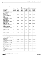
...Module 2 3.09 129.78 WS-X6024-10FL-MT 1.52 24-port 10BASE-FL Ethernet module 63.84 WS-X6066-SLB-APC 3.0 Content Switching Module 126.0 WS-X6101-OC12-SMF 2.10 88.2 WS-X6101-OC12-MMF 1-port ATM module WS-X6148-FE-SFP 2.3 48-port ... 443.40 476.0 557.14 510.87 481.96 OL-5781-04 Catalyst 6500 Series Switches Installation Guide D-5 Appendix D Chassis and Module Power and Heat Values Table D-4 Power Requirements and Heat Dissipation-Modules (continued) Model Number/ Module Type Module Module Current (A) Power @ 42 VDC (Watts) WS-F6700-DFC3C 1.65 Distributed Forwarding Card 3C...
...Module 2 3.09 129.78 WS-X6024-10FL-MT 1.52 24-port 10BASE-FL Ethernet module 63.84 WS-X6066-SLB-APC 3.0 Content Switching Module 126.0 WS-X6101-OC12-SMF 2.10 88.2 WS-X6101-OC12-MMF 1-port ATM module WS-X6148-FE-SFP 2.3 48-port ... 443.40 476.0 557.14 510.87 481.96 OL-5781-04 Catalyst 6500 Series Switches Installation Guide D-5 Appendix D Chassis and Module Power and Heat Values Table D-4 Power Requirements and Heat Dissipation-Modules (continued) Model Number/ Module Type Module Module Current (A) Power @ 42 VDC (Watts) WS-F6700-DFC3C 1.65 Distributed Forwarding Card 3C...

Installation Guide
Page 312
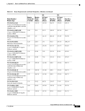
Appendix D Chassis and Module Power and Heat Values Table D-4 Power Requirements and Heat Dissipation-Modules (continued) Model Number/ Module Type Module Module Current (A) Power @ 42 VDC (Watts) WS-X6148A-GE-45AF 2.68 48-port 10/100/1000 Ethernet module with WS-...WS-X6196-RJ-21 2.74 96-port 10/100 Ethernet module 115.08 AC AC-Input Power (Watts) 140.70 Heat Diss. (BTU/HR) 480.49 DC DC-Input Power (Watts) 151.29 125.48 52.5 134.93 125.48 134.93 428.5 179.29....75 495.45 495.45 495.45 495.45 510.87 510.87 458.82 528.22 Catalyst 6500 Series Switches Installation Guide D-6 OL-5781-04
Appendix D Chassis and Module Power and Heat Values Table D-4 Power Requirements and Heat Dissipation-Modules (continued) Model Number/ Module Type Module Module Current (A) Power @ 42 VDC (Watts) WS-X6148A-GE-45AF 2.68 48-port 10/100/1000 Ethernet module with WS-...WS-X6196-RJ-21 2.74 96-port 10/100 Ethernet module 115.08 AC AC-Input Power (Watts) 140.70 Heat Diss. (BTU/HR) 480.49 DC DC-Input Power (Watts) 151.29 125.48 52.5 134.93 125.48 134.93 428.5 179.29....75 495.45 495.45 495.45 495.45 510.87 510.87 458.82 528.22 Catalyst 6500 Series Switches Installation Guide D-6 OL-5781-04
Installation Guide
Page 313
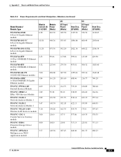
Appendix D Chassis and Module Power and Heat Values Table D-4 Power Requirements and Heat Dissipation-Modules (continued) Model Number/ Module Type Module Module Current (A) Power @ 42 VDC (Watts) WS-X6196-21AF 3.16 96-port 10/100 Ethernet module with ... module, MMF WS-X6248A-TEL 2.69 113 48-port 10/100 Ethernet module (telco) WS-X6302-MSM 5.20 Multilayer Switch Module 218.4 WS-X6316-GE-TX 5.15 16-port 1000BASE-T Gigabit Ethernet module 216.3 WS-X6324-100FX-MM 1.52 24....75 460.75 460.75 252.54 385.56 541.72 OL-5781-04 Catalyst 6500 Series Switches Installation Guide D-7
Appendix D Chassis and Module Power and Heat Values Table D-4 Power Requirements and Heat Dissipation-Modules (continued) Model Number/ Module Type Module Module Current (A) Power @ 42 VDC (Watts) WS-X6196-21AF 3.16 96-port 10/100 Ethernet module with ... module, MMF WS-X6248A-TEL 2.69 113 48-port 10/100 Ethernet module (telco) WS-X6302-MSM 5.20 Multilayer Switch Module 218.4 WS-X6316-GE-TX 5.15 16-port 1000BASE-T Gigabit Ethernet module 216.3 WS-X6324-100FX-MM 1.52 24....75 460.75 460.75 252.54 385.56 541.72 OL-5781-04 Catalyst 6500 Series Switches Installation Guide D-7
Installation Guide
Page 314
Appendix D Chassis and Module Power and Heat Values Table D-4 Power Requirements and Heat Dissipation-Modules (continued) Model Number/ Module Type Module Module Current (A) Power @ 42 VDC (Watts) WS-X6416-GE-MT 2.50 8-port 1000BASE-SX Gigabit Ethernet module 105.00 WS...WS-X6624-FXS 1.54 24-Port FXS analog interface module 64.68 AC AC-Input Power (Watts) 131.25 Heat Diss. (BTU/HR) 448.22 DC DC-Input Power (Watts) 141.13 173.25 591.65 186.29 178.50 609.58 191... 574.49 655.46 609.19 559.07 559.07 481.96 381.71 296.88 Catalyst 6500 Series Switches Installation Guide D-8 OL-5781-04
Appendix D Chassis and Module Power and Heat Values Table D-4 Power Requirements and Heat Dissipation-Modules (continued) Model Number/ Module Type Module Module Current (A) Power @ 42 VDC (Watts) WS-X6416-GE-MT 2.50 8-port 1000BASE-SX Gigabit Ethernet module 105.00 WS...WS-X6624-FXS 1.54 24-Port FXS analog interface module 64.68 AC AC-Input Power (Watts) 131.25 Heat Diss. (BTU/HR) 448.22 DC DC-Input Power (Watts) 141.13 173.25 591.65 186.29 178.50 609.58 191... 574.49 655.46 609.19 559.07 559.07 481.96 381.71 296.88 Catalyst 6500 Series Switches Installation Guide D-8 OL-5781-04
Installation Guide
Page 315
Appendix D Chassis and Module Power and Heat Values Table D-4 Power Requirements and Heat Dissipation-Modules (continued) Model Number/ Module Type WS-X6704-10GE 4-Port 10-Gigabit Ethernet module WS-X6708-10G...SVC-CSG-1 Content Services Gateway module WS-SVC-PSD-1 Persistent Storage Device module WS-SVC-MWAM-1 Multiprocessor WAN Application module Module Module Current (A) Power @ 42 VDC (Watts) 6.28 263.76 10.58 444.36 11.28 473.76 2.23 99.66 5.32 223.44 7.00 ... 788.48 364.36 557.14 668.95 597.63 578.35 771.13 688.23 OL-5781-04 Catalyst 6500 Series Switches Installation Guide D-9
Appendix D Chassis and Module Power and Heat Values Table D-4 Power Requirements and Heat Dissipation-Modules (continued) Model Number/ Module Type WS-X6704-10GE 4-Port 10-Gigabit Ethernet module WS-X6708-10G...SVC-CSG-1 Content Services Gateway module WS-SVC-PSD-1 Persistent Storage Device module WS-SVC-MWAM-1 Multiprocessor WAN Application module Module Module Current (A) Power @ 42 VDC (Watts) 6.28 263.76 10.58 444.36 11.28 473.76 2.23 99.66 5.32 223.44 7.00 ... 788.48 364.36 557.14 668.95 597.63 578.35 771.13 688.23 OL-5781-04 Catalyst 6500 Series Switches Installation Guide D-9

Installation Guide
Page 316
Appendix D Chassis and Module Power and Heat Values Table D-4 Power Requirements and Heat Dissipation-Modules (continued) Model Number/ Module Type Module Module Current (A) Power @ 42 VDC (Watts) WS-SVC-CMM 6.00 Communications Media module 252.0 ACE10-6500-K9 5.23 Applications Control Engine (ACE) module 219.66 WS-SVC-WISM-1-... 141.13 Heat Diss. (BTU/HR) 1156.69 1008.25 1170.19 771.31 566.78 771.13 771.13 414.48 481.96 D-10 Catalyst 6500 Series Switches Installation Guide OL-5781-04
Appendix D Chassis and Module Power and Heat Values Table D-4 Power Requirements and Heat Dissipation-Modules (continued) Model Number/ Module Type Module Module Current (A) Power @ 42 VDC (Watts) WS-SVC-CMM 6.00 Communications Media module 252.0 ACE10-6500-K9 5.23 Applications Control Engine (ACE) module 219.66 WS-SVC-WISM-1-... 141.13 Heat Diss. (BTU/HR) 1156.69 1008.25 1170.19 771.31 566.78 771.13 771.13 414.48 481.96 D-10 Catalyst 6500 Series Switches Installation Guide OL-5781-04

Installation Guide
Page 332
... switches 1-41 Catalyst 6509-NEB-A switches 1-46 Catalyst 6513 switches 1-51 port mode switches mode 1 B-27 mode 2 B-28 using B-26 power shut down sequence A-54 troubleshooting E-2 power and heat values chassis D-1 fan trays D-1 IP phones D-2 modules D-4 supervisor engines D-3 power cords See AC-input power cords power down sequence A-54 power entry modules Catalyst 6503-E switches requirement 1-9 Catalyst 6503 switches requirement 1-4 description A-15 form factor (figure) A-4 overview A-4 removing and installing 4-51 power requirements...
... switches 1-41 Catalyst 6509-NEB-A switches 1-46 Catalyst 6513 switches 1-51 port mode switches mode 1 B-27 mode 2 B-28 using B-26 power shut down sequence A-54 troubleshooting E-2 power and heat values chassis D-1 fan trays D-1 IP phones D-2 modules D-4 supervisor engines D-3 power cords See AC-input power cords power down sequence A-54 power entry modules Catalyst 6503-E switches requirement 1-9 Catalyst 6503 switches requirement 1-4 description A-15 form factor (figure) A-4 overview A-4 removing and installing 4-51 power requirements...
