
Installation Guide
Page 8
... A-39 4000 W Power Supply AC Power Cords A-42 6000 W AC-Input Power Supply A-43 6000 W Power Supply Specifications A-44 6000 W Power Supply AC Power Cords A-46 AC Power Cord Illustrations A-47 Power Supply Redundancy A-57 B A P P E N D I X Transceivers, Module Connectors, and Cable Specifications B-1 Transceivers B-1 100-MB Transceiver Modules B-2 1-GB Transceiver Modules B-3 10-GB Transceiver Modules B-8 WDM Transceiver Modules B-10 Catalyst 6500 Series Switches Installation Guide...
... A-39 4000 W Power Supply AC Power Cords A-42 6000 W AC-Input Power Supply A-43 6000 W Power Supply Specifications A-44 6000 W Power Supply AC Power Cords A-46 AC Power Cord Illustrations A-47 Power Supply Redundancy A-57 B A P P E N D I X Transceivers, Module Connectors, and Cable Specifications B-1 Transceivers B-1 100-MB Transceiver Modules B-2 1-GB Transceiver Modules B-3 10-GB Transceiver Modules B-8 WDM Transceiver Modules B-10 Catalyst 6500 Series Switches Installation Guide...
Installation Guide
Page 11
...Catalyst 6500 series switch. OL-5781-04 Catalyst 6500 Series Switches Installation Guide xi Installing the Switch Describes how to consider when preparing your Catalyst 6500 series switch. Removal and Provides procedures for the Catalyst 6500 series switch AC-input and DC-input power supplies and the AC power cords... and functionality of the Catalyst 6500 series switches. Organization This publication is organized, and its document conventions. Power Supply Specifications Provides specifications for removing and installing chassis Replacement Procedures components.
...Catalyst 6500 series switch. OL-5781-04 Catalyst 6500 Series Switches Installation Guide xi Installing the Switch Describes how to consider when preparing your Catalyst 6500 series switch. Removal and Provides procedures for the Catalyst 6500 series switch AC-input and DC-input power supplies and the AC power cords... and functionality of the Catalyst 6500 series switches. Organization This publication is organized, and its document conventions. Power Supply Specifications Provides specifications for removing and installing chassis Replacement Procedures components.
Installation Guide
Page 87
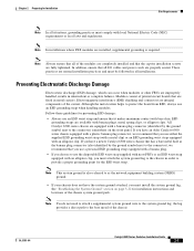
...a banana plug. • If you have a newer Catalyst 6500 series chassis that has a bare metal hole as the network equipment building system (NEBS) ground. • If your chassis does not have an older Catalyst 6500 series chassis equipped with a plastic banana plug connector, we recommend that... power cords are fixed in metal carriers. If you have the system ground attached, you must attach the system ground lug to the chassis in intermittent or complete failures. Note Always ensure that are properly seated. Modules consist of the chassis OL-5781-04 Catalyst 6500 Series Switches ...
...a banana plug. • If you have a newer Catalyst 6500 series chassis that has a bare metal hole as the network equipment building system (NEBS) ground. • If your chassis does not have an older Catalyst 6500 series chassis equipped with a plastic banana plug connector, we recommend that... power cords are fixed in metal carriers. If you have the system ground attached, you must attach the system ground lug to the chassis in intermittent or complete failures. Note Always ensure that are properly seated. Modules consist of the chassis OL-5781-04 Catalyst 6500 Series Switches ...
Installation Guide
Page 99
...; In systems configured with the Catalyst 6500 series switch power supplies which use an uninterruptible power supply (UPS) to protect against power failures at your system might be susceptible to total power failure due to a fault in the system. • The AC-input power supply has a detachable power cord (except for the 4000 W power supplies) that use ferroresonant technology can...
...; In systems configured with the Catalyst 6500 series switch power supplies which use an uninterruptible power supply (UPS) to protect against power failures at your system might be susceptible to total power failure due to a fault in the system. • The AC-input power supply has a detachable power cord (except for the 4000 W power supplies) that use ferroresonant technology can...

Installation Guide
Page 143
... page 4-51. For information on removing the power entry module (PEM), see the "Removing and Installing the Power Entry Modules (PEMs)" section on the Catalyst 6503 and Catalyst 6503-E switch chassis.) Disconnect the power cord from the power connection on the backplane when the system is ...power supply filler plate (Cisco part number 800-16727-01 for the Catalyst 6503 and 6503-E switches.) Grasp the power supply handle with one hand, and slide the power supply part of the way out of the chassis. Remove the power cord from the power source. OL-5781-04 Catalyst 6500 Series Switches...
... page 4-51. For information on removing the power entry module (PEM), see the "Removing and Installing the Power Entry Modules (PEMs)" section on the Catalyst 6503 and Catalyst 6503-E switch chassis.) Disconnect the power cord from the power connection on the backplane when the system is ...power supply filler plate (Cisco part number 800-16727-01 for the Catalyst 6503 and 6503-E switches.) Grasp the power supply handle with one hand, and slide the power supply part of the way out of the chassis. Remove the power cord from the power source. OL-5781-04 Catalyst 6500 Series Switches...

Installation Guide
Page 145
... installation screws must be tight to install an AC-input power supply: Step 1 Step 2 Step 3 Step 4 Ensure that the power supply is fully seated in Figure 4-3. OL-5781-04 Catalyst 6500 Series Switches Installation Guide 4-5 Step 5 At the front of the chassis, plug the power cord into the power supply bay. Chapter 4 Removal and Replacement Procedures Removing and...
... installation screws must be tight to install an AC-input power supply: Step 1 Step 2 Step 3 Step 4 Ensure that the power supply is fully seated in Figure 4-3. OL-5781-04 Catalyst 6500 Series Switches Installation Guide 4-5 Step 5 At the front of the chassis, plug the power cord into the power supply bay. Chapter 4 Removal and Replacement Procedures Removing and...
Installation Guide
Page 146
...the power supply operation by checking that the power supply LEDs are in the Catalyst 6504-E switch. Removing and Installing the 2700 W AC-Input Power Supply This section describes how to a separate input source. Catalyst 6500 Series Switches ...power supply to remove and install the 2700 W AC-input power supply in the following topics: • Required Tools, page 4-6 • Removing a 2700 W AC-Input Power Supply, page 4-7 • Installing a 2700 W AC-Input Power Supply, page 4-8 Warning Hazardous voltage or energy is present on the power supply. In case of the power cord...
...the power supply operation by checking that the power supply LEDs are in the Catalyst 6504-E switch. Removing and Installing the 2700 W AC-Input Power Supply This section describes how to a separate input source. Catalyst 6500 Series Switches ...power supply to remove and install the 2700 W AC-input power supply in the following topics: • Required Tools, page 4-6 • Removing a 2700 W AC-Input Power Supply, page 4-7 • Installing a 2700 W AC-Input Power Supply, page 4-8 Warning Hazardous voltage or energy is present on the power supply. In case of the power cord...

Installation Guide
Page 147
... the power switch to the power supply. OL-5781-04 Catalyst 6500 Series Switches Installation Guide 4-7 Do not touch the metal prongs on the power cord while it is still connected to the Off (0) position on the power supply you are removing. Loosen the captive installation screws on the power supply. Disconnect the power cord from the power connection on the power supply...
... the power switch to the power supply. OL-5781-04 Catalyst 6500 Series Switches Installation Guide 4-7 Do not touch the metal prongs on the power cord while it is still connected to the Off (0) position on the power supply you are removing. Loosen the captive installation screws on the power supply. Disconnect the power cord from the power connection on the power supply...
Installation Guide
Page 149
... W, 4000 W, and 6000 W AC-Input Power Supplies, page 4-11 All six power supplies have the same form factor and are in the Catalyst 6500 series switches that the power supply LEDs are removed and installed using the same procedures. OL-5781-04 Catalyst 6500 Series Switches Installation Guide 4-9 In case of the power cord to ensure protective grounding continuity...
... W, 4000 W, and 6000 W AC-Input Power Supplies, page 4-11 All six power supplies have the same form factor and are in the Catalyst 6500 series switches that the power supply LEDs are removed and installed using the same procedures. OL-5781-04 Catalyst 6500 Series Switches Installation Guide 4-9 In case of the power cord to ensure protective grounding continuity...

Installation Guide
Page 150
...on the power supply that you are removing. (See Figure 4-6.) Turning the power switch off also disengages a pawl that unlocks the power supply from the chassis. If the power supply bay is hard wired to remain empty, install a blank faceplate (Cisco part ...chassis. Statement 1034 To remove an AC-input power supply, follow these steps: Step 1 Step 2 Step 3 Turn the power switch to install and remove power supplies. Use caution when servicing. Note The AC power cord for the 4000 W power supply is to the power supply and cannot be removed. Catalyst 6500 series AC-input power...
...on the power supply that you are removing. (See Figure 4-6.) Turning the power switch off also disengages a pawl that unlocks the power supply from the chassis. If the power supply bay is hard wired to remain empty, install a blank faceplate (Cisco part ...chassis. Statement 1034 To remove an AC-input power supply, follow these steps: Step 1 Step 2 Step 3 Turn the power switch to install and remove power supplies. Use caution when servicing. Note The AC power cord for the 4000 W power supply is to the power supply and cannot be removed. Catalyst 6500 series AC-input power...
Installation Guide
Page 152
In case of supported AC power cords. Switching the power switch to a separate input source. Refer to an AC-input power source. Tighten the power supply captive installation screw. (See Figure 4-6.) Plug the power cord into the power supply bay. Place your other end of the power cord to Appendix A for troubleshooting information. 4-12 Catalyst 6500 Series Switches Installation Guide OL-5781-04 Slide the...
In case of supported AC power cords. Switching the power switch to a separate input source. Refer to an AC-input power source. Tighten the power supply captive installation screw. (See Figure 4-6.) Plug the power cord into the power supply bay. Place your other end of the power cord to Appendix A for troubleshooting information. 4-12 Catalyst 6500 Series Switches Installation Guide OL-5781-04 Slide the...

Installation Guide
Page 192
... the power cord when it completely out of the chassis. Remove the power cord from the power connection on the PEM that you are removing. (See Figure 4-40.) Disconnect the power cord from the power source. Do not touch the metal prongs embedded in Figure 4-43, and slide it is to remain empty, install a blank PEM filler plate (Cisco part...
... the power cord when it completely out of the chassis. Remove the power cord from the power connection on the PEM that you are removing. (See Figure 4-40.) Disconnect the power cord from the power source. Do not touch the metal prongs embedded in Figure 4-43, and slide it is to remain empty, install a blank PEM filler plate (Cisco part...

Installation Guide
Page 194
...power supplies, connect each power supply to prevent accidental power restoration while you are removing. Step 7 Turn the power switch to the DC circuit for a list of supported AC power cords.) Step 6 Connect the other end of the chassis so that you have access to disconnect the system ground connection. 4-54 Catalyst 6500 Series Switches...input PEM: Step 1 Step 2 Step 3 Step 4 Verify that power is present on the PEM. (See Figure 4-44.) Slide the PEM part way out of the power cord to an AC-input power source. Loosen the captive installation screws on the backplane when the ...
...power supplies, connect each power supply to prevent accidental power restoration while you are removing. Step 7 Turn the power switch to the DC circuit for a list of supported AC power cords.) Step 6 Connect the other end of the chassis so that you have access to disconnect the system ground connection. 4-54 Catalyst 6500 Series Switches...input PEM: Step 1 Step 2 Step 3 Step 4 Verify that power is present on the PEM. (See Figure 4-44.) Slide the PEM part way out of the power cord to an AC-input power source. Loosen the captive installation screws on the backplane when the ...

Installation Guide
Page 216
... phase between multiple power supplies in the same chassis, which means that power cord 1 can be plugged into phase B. 950 W maximum (100-240 VAC) -48 VDC to local and national codes • All Catalyst 6500 series AC-input power supplies require single-...19.15 A @ +50 V • 15 A @ +1.5 V • 2.5 A @ +3.3 V • 19.15 A @ +50 V • 20 ms minimum (AC-input power supply) • 4 ms (DC-input power supply) • 4441 BTU/hour (approx.) AC-input power supply • 4632 BTU/hour (approx.) DC-input power supply Catalyst 6500 Series Switches Installation Guide A-6 OL-5781-04
... phase between multiple power supplies in the same chassis, which means that power cord 1 can be plugged into phase B. 950 W maximum (100-240 VAC) -48 VDC to local and national codes • All Catalyst 6500 series AC-input power supplies require single-...19.15 A @ +50 V • 15 A @ +1.5 V • 2.5 A @ +3.3 V • 19.15 A @ +50 V • 20 ms minimum (AC-input power supply) • 4 ms (DC-input power supply) • 4441 BTU/hour (approx.) AC-input power supply • 4632 BTU/hour (approx.) DC-input power supply Catalyst 6500 Series Switches Installation Guide A-6 OL-5781-04

Installation Guide
Page 218
... Figure A-20 Figure A-21 Catalyst 6500 Series Switches Installation Guide A-8 OL-5781-04 The appliance connector has a 90° left bend. These power cords plug into the 950 W PEM(PEM-15A-AC), not directly into the power supply. The table includes references to power cord illustrations. Table A-4 950 W AC-Input Power Supply Power Cords Locale Power Cord Part Number Australia, New Zealand...
... Figure A-20 Figure A-21 Catalyst 6500 Series Switches Installation Guide A-8 OL-5781-04 The appliance connector has a 90° left bend. These power cords plug into the 950 W PEM(PEM-15A-AC), not directly into the power supply. The table includes references to power cord illustrations. Table A-4 950 W AC-Input Power Supply Power Cords Locale Power Cord Part Number Australia, New Zealand...

Installation Guide
Page 220
... 1250 kVA Each chassis power supply should have its own dedicated, fused-branch circuit: • For North America-15 A or 20 A • For International-Circuits sized to 240 VAC (±10% for the 1000 W AC-input power supply. A-10 Catalyst 6500 Series Switches Installation Guide OL-5781... input with multiple AC inputs, which means that power cord 1 can be plugged into phase A and power cord 2 can be operating from phase A and PS2 can be operating from phase B. - PFC reduces the reactive component in the same chassis, which means that PS1 can be plugged into phase...
... 1250 kVA Each chassis power supply should have its own dedicated, fused-branch circuit: • For North America-15 A or 20 A • For International-Circuits sized to 240 VAC (±10% for the 1000 W AC-input power supply. A-10 Catalyst 6500 Series Switches Installation Guide OL-5781... input with multiple AC inputs, which means that power cord 1 can be plugged into phase A and power cord 2 can be operating from phase A and PS2 can be operating from phase B. - PFC reduces the reactive component in the same chassis, which means that PS1 can be plugged into phase...

Installation Guide
Page 222
... A, 250 VAC 10 A, 250 VAC 15 A, 125 VAC 10 A, 250 VAC Power Cord Reference Illustration Figure A-22 Figure A-23 Figure A-24 Figure A-25 Figure A-26 Figure A-27 A-12 Catalyst 6500 Series Switches Installation Guide OL-5781-04 Table A-6 1000 W AC-Input Power Supply Power Cords Locale Power Cord Part Number Argentina CAB-7KACR= Australia, New Zealand CAB-7KACA= Continental...
... A, 250 VAC 10 A, 250 VAC 15 A, 125 VAC 10 A, 250 VAC Power Cord Reference Illustration Figure A-22 Figure A-23 Figure A-24 Figure A-25 Figure A-26 Figure A-27 A-12 Catalyst 6500 Series Switches Installation Guide OL-5781-04 Table A-6 1000 W AC-Input Power Supply Power Cords Locale Power Cord Part Number Argentina CAB-7KACR= Australia, New Zealand CAB-7KACA= Continental...

Installation Guide
Page 224
... - Source AC can be out of phase between AC inputs on all Catalyst 6500 series AC-input power supplies. A-14 Catalyst 6500 Series Switches Installation Guide OL-5781-04 PFC reduces the reactive component in the same chassis, which means that PS1 can be operating from phase B. - Table A-7...Branch circuit requirement (AC-input) Description Autoranging input with multiple AC inputs, which means that power cord 1 can be operating from phase A and PS2 can be plugged into phase A and power cord 2 can be plugged into phase B. Source AC can be out of phase between multiple...
... - Source AC can be out of phase between AC inputs on all Catalyst 6500 series AC-input power supplies. A-14 Catalyst 6500 Series Switches Installation Guide OL-5781-04 PFC reduces the reactive component in the same chassis, which means that PS1 can be operating from phase B. - Table A-7...Branch circuit requirement (AC-input) Description Autoranging input with multiple AC inputs, which means that power cord 1 can be operating from phase A and PS2 can be plugged into phase A and power cord 2 can be plugged into phase B. Source AC can be out of phase between multiple...

Installation Guide
Page 227
...32 Figure A-33 Figure A-34 Figure A-35 Figure A-36 Figure A-37 OL-5781-04 Catalyst 6500 Series Switches Installation Guide A-17 Table A-8 1300 W Power Supply AC Power Cords Locale Power Cord Part Number Source Plug Type Argentina CAB-7513ACR= IRAM 2073 Australia, New Zealand CAB-7513ACA=...SEV 1011 BS 13632 1. For Japan, ask your local electrical contractor to power cord illustrations. The table includes references to prepare the NEMA 5-20 power plug. 2. Note All 1300 W power supply power cords are available for the AC power cords that are 14 feet (4.3 meters) in length.
...32 Figure A-33 Figure A-34 Figure A-35 Figure A-36 Figure A-37 OL-5781-04 Catalyst 6500 Series Switches Installation Guide A-17 Table A-8 1300 W Power Supply AC Power Cords Locale Power Cord Part Number Source Plug Type Argentina CAB-7513ACR= IRAM 2073 Australia, New Zealand CAB-7513ACA=...SEV 1011 BS 13632 1. For Japan, ask your local electrical contractor to power cord illustrations. The table includes references to prepare the NEMA 5-20 power plug. 2. Note All 1300 W power supply power cords are available for the AC power cords that are 14 feet (4.3 meters) in length.

Installation Guide
Page 229
...-04 Catalyst 6500 Series Switches Installation Guide A-19 Note Power factor correction is a standard feature on power supplies that are fully isolated. - Source AC can be operating from phase B. - PFC reduces the reactive component in the same chassis, which means that PS1 can be operating from phase A and PS2 can be plugged into phase A and power cord...
...-04 Catalyst 6500 Series Switches Installation Guide A-19 Note Power factor correction is a standard feature on power supplies that are fully isolated. - Source AC can be operating from phase B. - PFC reduces the reactive component in the same chassis, which means that PS1 can be operating from phase A and PS2 can be plugged into phase A and power cord...
