Installation Guide
Page 4
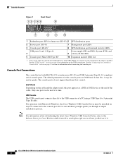
... See the "Connecting the Controller's Console Port" section on page 22 section for information on page 4 for information about downloading the latest Cisco Windows USB Console Driver, refer to the console port. See the "USB Console" section on the USB console port. Only one console ... USB ports 0 and 1 (Type A) 4 5 Console port (Mini USB Type B)1 Power supply (PS1 and PS2), System (SYS), and 9 Alarm (ALM) LEDs 10 Expansion module (EM) slot 1. For operation with Microsoft Windows, the Cisco Windows USB Console Driver must be used , this port appears as a DTE or DCE ...
... See the "Connecting the Controller's Console Port" section on page 22 section for information on page 4 for information about downloading the latest Cisco Windows USB Console Driver, refer to the console port. See the "USB Console" section on the USB console port. Only one console ... USB ports 0 and 1 (Type A) 4 5 Console port (Mini USB Type B)1 Power supply (PS1 and PS2), System (SYS), and 9 Alarm (ALM) LEDs 10 Expansion module (EM) slot 1. For operation with Microsoft Windows, the Cisco Windows USB Console Driver must be used , this port appears as a DTE or DCE ...

Installation Guide
Page 5
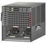
... An amber LED could indicate an error or a possible hardware failure. 78-18998-01 Cisco 5500 Series Wireless Controller Installation Guide 5 Figure 2 12 Back Panel 251198 3 4 1 Power supply PS1 2 Power supply PS1 on/off switch 3 Power supply PS1 AC cable connection 5 4 Power supply PS2 slot with a power supply, a blank power supply cover, and a fan tray. The LED indicators are not compatible. Controller Overview With...
... An amber LED could indicate an error or a possible hardware failure. 78-18998-01 Cisco 5500 Series Wireless Controller Installation Guide 5 Figure 2 12 Back Panel 251198 3 4 1 Power supply PS1 2 Power supply PS1 on/off switch 3 Power supply PS1 AC cable connection 5 4 Power supply PS2 slot with a power supply, a blank power supply cover, and a fan tray. The LED indicators are not compatible. Controller Overview With...
Installation Guide
Page 6
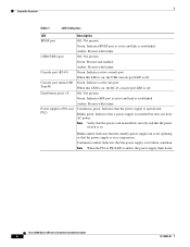
... Cisco 5500 Series Wireless Controller Installation Guide 6 78-18998-01 Green: Present and enabled. Green: Indicates active aux port. When this LED is on , the RJ-45 console port LED is on. Continuous green: Indicates that the power supply is in installed correctly and that the power switch is... off . When this LED is on , the USB console port LED is installed but does not have AC power. Blinks amber: Indicates that the standby power supply fan is not spinning or that a power supply is off . Off...
... Cisco 5500 Series Wireless Controller Installation Guide 6 78-18998-01 Green: Present and enabled. Green: Indicates active aux port. When this LED is on , the RJ-45 console port LED is on. Continuous green: Indicates that the power supply is in installed correctly and that the power switch is... off . When this LED is on , the USB console port LED is installed but does not have AC power. Blinks amber: Indicates that the standby power supply fan is not spinning or that a power supply is off . Off...
Installation Guide
Page 8
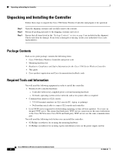
Return all items listed in the "Package Contents" section on the power supply and fan Cisco 5500 Series Wireless Controller Installation Guide 8 78-18998-01 If any item is damaged or missing, notify your authorized Cisco sales representative. VT-100 terminal emulator on the same workstation as required • Command-line interface (CLI) console - Check...
Return all items listed in the "Package Contents" section on the power supply and fan Cisco 5500 Series Wireless Controller Installation Guide 8 78-18998-01 If any item is damaged or missing, notify your authorized Cisco sales representative. VT-100 terminal emulator on the same workstation as required • Command-line interface (CLI) console - Check...
Installation Guide
Page 12
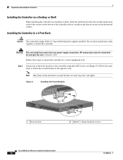
... chassis, and place the chassis on each bracket are used (top, left, and right). All connections must work together to de-energize the unit. Statement 1028 Follow these steps to mount the controller in a 4-Post Rack Caution The controller weighs 20 lbs (9.1 kg) with both power supplies ...installed. Figure 4 Installing the Front Brackets RP SP USB0 USB1 CONSOLE EN EN Cisco 5500 Series Wireless Controller 12 34 56 78 Model 5508 PS1 PS2 SYS ACT 1 Front bracket 12 ...
... chassis, and place the chassis on each bracket are used (top, left, and right). All connections must work together to de-energize the unit. Statement 1028 Follow these steps to mount the controller in a 4-Post Rack Caution The controller weighs 20 lbs (9.1 kg) with both power supplies ...installed. Figure 4 Installing the Front Brackets RP SP USB0 USB1 CONSOLE EN EN Cisco 5500 Series Wireless Controller 12 34 56 78 Model 5508 PS1 PS2 SYS ACT 1 Front bracket 12 ...

Installation Guide
Page 16
...removed to the controller using three M4 screws (see Figure 11). Note Only three of the front brackets to de-energize the unit. Cisco 5500 Series Wireless Controller Installation Guide 16 78-18998-01 Follow the same steps to attach the second bracket to install the controller. Figure... Follow these steps to prevent the cables from obscuring the front panel of the switch and the other devices installed in a 2-Post Rack-Flush Mount Caution The controller weighs 20 lbs (9.1 kg) with both power supplies installed. Note We recommend that you attach the cable guide to flush mount the...
...removed to the controller using three M4 screws (see Figure 11). Note Only three of the front brackets to de-energize the unit. Cisco 5500 Series Wireless Controller Installation Guide 16 78-18998-01 Follow the same steps to attach the second bracket to install the controller. Figure... Follow these steps to prevent the cables from obscuring the front panel of the switch and the other devices installed in a 2-Post Rack-Flush Mount Caution The controller weighs 20 lbs (9.1 kg) with both power supplies installed. Note We recommend that you attach the cable guide to flush mount the...

Installation Guide
Page 18
... EN EN Cisco 5500 Series Wireless Controller 12 34 56 78 Model 5508 PS1 PS2 SYS ACT 205855 Installing the Controller in a 2-Post Rack-Mid-Mount Caution The controller weighs 20 lbs (9.1 kg) with both power supplies installed. Statement 1028 Note When you use the mid-mount option, you cannot ground the chassis using...
... EN EN Cisco 5500 Series Wireless Controller 12 34 56 78 Model 5508 PS1 PS2 SYS ACT 205855 Installing the Controller in a 2-Post Rack-Mid-Mount Caution The controller weighs 20 lbs (9.1 kg) with both power supplies installed. Statement 1028 Note When you use the mid-mount option, you cannot ground the chassis using...

Installation Guide
Page 20
... type, and the grounding conductors should connect to protective earth ground at the service equipment. You will need to the chassis must be grounded. Caution All power supplies must always be made first and disconnected last. Cisco 5500 Series Wireless Controller Installation Guide 20 78-18998-01 Unpacking and Installing the Controller Grounding the...
... type, and the grounding conductors should connect to protective earth ground at the service equipment. You will need to the chassis must be grounded. Caution All power supplies must always be made first and disconnected last. Cisco 5500 Series Wireless Controller Installation Guide 20 78-18998-01 Unpacking and Installing the Controller Grounding the...
Installation Guide
Page 22
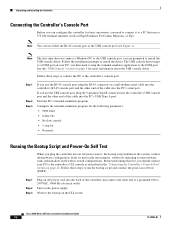
... the Controller's Console Port" section on page 22. Step 1 Step 2 Step 3 Plug an AC power cord into memory, verifies its operating system software load, and initializes itself with its stored configurations. Cisco 5500 Series Wireless Controller Installation Guide 22 78-18998-01 The USB console driver maps to the... console driver. Before performing this test, you are prompted to 240 VAC, 50/60 Hz electrical outlet. Observe the bootup on the power supply. Follow the installation prompts to the controller's console port: Step 1 Step 2 Step 3 If you plug the controller into an AC...
... the Controller's Console Port" section on page 22. Step 1 Step 2 Step 3 Plug an AC power cord into memory, verifies its operating system software load, and initializes itself with its stored configurations. Cisco 5500 Series Wireless Controller Installation Guide 22 78-18998-01 The USB console driver maps to the... console driver. Before performing this test, you are prompted to 240 VAC, 50/60 Hz electrical outlet. Observe the bootup on the power supply. Follow the installation prompts to the controller's console port: Step 1 Step 2 Step 3 If you plug the controller into an AC...
Installation Guide
Page 25
... define clusters of the mobility group/RF group to which will supply IP addresses to automatically form an RF group with the same virtual...and connectivity to optimize RRM parameter settings, such as channel and transmit power assignment, for in-band management of the 802.11b, 802.11a,... interface is the default interface for the group. 78-18998-01 Cisco 5500 Series Wireless Controller Installation Guide 25 Note The virtual interface is...controller and allows access points that will be used to match the switch interface configuration. Step 11 Step 12 Step 13 Step 14 Enter the...
... define clusters of the mobility group/RF group to which will supply IP addresses to automatically form an RF group with the same virtual...and connectivity to optimize RRM parameter settings, such as channel and transmit power assignment, for in-band management of the 802.11b, 802.11a,... interface is the default interface for the group. 78-18998-01 Cisco 5500 Series Wireless Controller Installation Guide 25 Note The virtual interface is...controller and allows access points that will be used to match the switch interface configuration. Step 11 Step 12 Step 13 Step 14 Enter the...
Installation Guide
Page 28
... power supply units, the power supplies are hot swappable; Also, the power supplies are redundant. Note If only one used , you must switch off and unplug the power supply. Either power supply continues to associate. The service-port interface enables the controller to replace a power supply. As soon as the controller is operational, it in the event of a network failure. Refer to the Cisco...
... power supply units, the power supplies are hot swappable; Also, the power supplies are redundant. Note If only one used , you must switch off and unplug the power supply. Either power supply continues to associate. The service-port interface enables the controller to replace a power supply. As soon as the controller is operational, it in the event of a network failure. Refer to the Cisco...

Installation Guide
Page 29
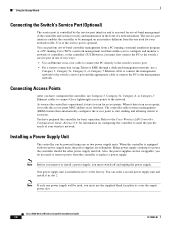
...these steps to tighten the captive screw. Figure 19 Controller Power Supply Slots 1 2 251205 1 Slot 1 with power supply 2 Slot 2 with empty power supply slot with the slot so that both power supply units are hot swappable. Make sure that the unit's power input receptacle is firmly seated in a safe place for ...to install a power supply unit. Do not overtighten. Plug the power cord into the power supply unit and the other end into the slot until it in the card electrical connector. Remove the slot cover and store it is on . 78-18998-01 Cisco 5500 Series Wireless...
...these steps to tighten the captive screw. Figure 19 Controller Power Supply Slots 1 2 251205 1 Slot 1 with power supply 2 Slot 2 with empty power supply slot with the slot so that both power supply units are hot swappable. Make sure that the unit's power input receptacle is firmly seated in a safe place for ...to install a power supply unit. Do not overtighten. Plug the power cord into the power supply unit and the other end into the slot until it in the card electrical connector. Remove the slot cover and store it is on . 78-18998-01 Cisco 5500 Series Wireless...
Installation Guide
Page 31
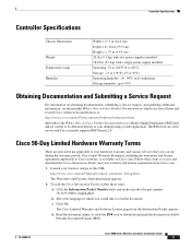
...and make sure that you would like to read the Cisco Information Packet, follow these steps to access and download the Cisco Information Packet and your browser, and go to this URL: http://www.cisco.com/en/US/products/prod_warranties_listing.html The Warranties and License.... Controller Specifications Controller Specifications Chassis Dimensions Weight Temperature range Humidity Width = 17.3 in (44.0 cm) Depth = 21.20 in (53.9 cm) Height = 1.75 in (4.45 cm) 20 lbs (9.1 kg) with two power supplies installed 18.8 lbs (8.5 kg) with a single power supply installed Operating: 32 to 104...
...and make sure that you would like to read the Cisco Information Packet, follow these steps to access and download the Cisco Information Packet and your browser, and go to this URL: http://www.cisco.com/en/US/products/prod_warranties_listing.html The Warranties and License.... Controller Specifications Controller Specifications Chassis Dimensions Weight Temperature range Humidity Width = 17.3 in (44.0 cm) Depth = 21.20 in (53.9 cm) Height = 1.75 in (4.45 cm) 20 lbs (9.1 kg) with two power supplies installed 18.8 lbs (8.5 kg) with a single power supply installed Operating: 32 to 104...

